

جهاز كشف عطل القوس: كيفية عمله وكيفية الاختيار
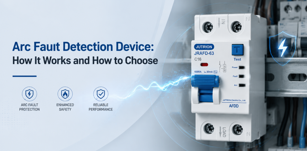
جهاز كشف القوس الكهربائي JUTRION AFDD للحماية من القوس الكهربائي والسلامة الكهربائية"16 A AFDD" ليست مواصفة كاملة. فهي لا تخبر المورد بأي معيار منتج للكشف عن قوس كهربائي ينطبق، أو ما إذا كان يجب دمج حماية الحمل الزائد والتيار المتبقي، أو ما هي سعة التيار القصر المطلوبة، أو كيفية التعامل مع النيوترال، أو ما إذا كان الجهاز معتمدًا للوحة التوزيع المقصودة. يمكن أن تؤدي هذه الإغفالات إلى تحويل مفهوم حماية الحريق الصحيح إلى قائمة مواد غير متوافقة.
قاعدة الاختيار العملية هي العمل من الدائرة النهائية إلى الخارج. أولاً تأكد مما إذا كان كود التركيب يتطلب أو يوصي بحماية من القوس الكهربائي لتلك الدائرة. ثم اختر بنية الحماية، ونسق كل تصنيف كهربائي، وطابق الجهاز مع لوحة التوزيع. جهاز كشف القوس الكهربائي (AFDD) يضيف حماية ضد الأقواس الخطرة المتوالية والمتوازية؛ ولا يحل تلقائيًا محل MCB أو RCD أو RCBO أو SPD أو ممارسات التوصيل السليمة.
النقاط الرئيسية
- تكتشف أجهزة AFDD أنماط القوس الخطيرة على التوالي والتوازي التي قد لا تنتج تيار حمل زائد أو تسرب أرضي كافٍ لتشغيل MCB أو RCD تقليدي.
- يكمل جهاز AFDD أجهزة الحماية الأخرى بدلاً من استبدالها. يجب توفير حماية الحمل الزائد والقصر والتيار المتبقي والاندفاع حيثما يلزم ذلك.
- معايير المنتج والتركيب تجيب عن أسئلة مختلفة. يغطي IEC 62606 متطلبات منتج AFDD، بينما تحدد قواعد التوصيل الوطنية أين تكون الحماية مطلوبة أو موصى بها.
- تؤثر بنية الحماية على تصميم الدائرة بالكامل. توفر AFDD المستقل وAFDD-MCB وAFDD-RCBO والتوليفات المعيارية المعتمدة مجموعات مختلفة من الوظائف.
- التيار المقنن وحده لا يكفي للاختيار. يجب أيضًا مطابقة الجهد والتردد والأقطاب والمنحنى وسعة القطع ونوع RCD وقضيب التوصيل والأطراف وعرض الوحدة وظروف العلبة.
- التركيب والاختبار الصحيحان ضروريان. يؤثر توجيه المحايد وعزم الأطراف والظروف الحرارية وإجراءات الاختبار ومؤشر سبب الفصل على موثوقية التشغيل وتحديد الأعطال.
استخدم النقاط السبع التالية لمقارنة خيارات AFDD لدائرة محددة وسوق مستهدف.
| القرار | السؤال المطلوب الإجابة عنه | لماذا يغير الاختيار |
|---|---|---|
| النطاق التنظيمي | أي دولة وإصدار كود ونوع إشغال ونوع دائرة وتيار مقنن ينطبق؟ | متطلبات AFDD ليست عالمية ويمكن أن تتغير حسب الاعتماد الوطني. |
| نظام المنتج | هل المشروع هو IEC AFDD أو UK BS EN AFDD أو AFCI أمريكا الشمالية؟ | تختلف المعايير والتصنيفات والشهادات وواجهات اللوحات والمصطلحات. |
| بنية الحماية | هل كشف القوس مستقل أم مدمج مع MCB أم مدمج مع RCBO؟ | يحدد الاختيار أجهزة الحماية الإضافية التي تظل ضرورية. |
| التصنيفات الكهربائية | ما الجهد والتردد والتيار والمنحنى ونوع التيار المتبقي وسعة القطع المطلوبة؟ | كل قيمة تتوافق مع حالة تشغيل أو عطل مختلفة. |
| واجهة التجميع | أي لوحة وقضيب توصيل وأقطاب وترتيب محايد وعرض وحدة وملحقات تنطبق؟ | الملاءمة الميكانيكية وحدها لا تثبت التوافق الكهربائي أو توافق الشهادات. |
| العواقب التشغيلية | ماذا يحدث إذا فصلت الدائرة، وكيف سيتم تحديد السبب؟ | تؤثر الاستمرارية والانتقائية والإشارة ووصول الصيانة على التصميم. |
| دعم المنتج | أي أوراق البيانات والتعليمات والشهادات والعينات وخدمات التخصيص ستساعد المشروع؟ | التوثيق الواضح يجعل المقارنة والتركيب والاعتماد وإعادة الطلب أسهل. |
يساعد هذا الترتيب المشترين على مقارنة المنتجات المكافئة والتواصل بمتطلباتهم بكفاءة. كما يفصل بين القرارات التي غالبًا ما يتم الخلط بينها. على سبيل المثال، منحنى تعثر C يصف وظيفة التيار الزائد؛ ولا يصف حساسية القوس. علامة 30 mA تصف حماية التيار المتبقي؛ ولا تثبت أن الجهاز يتضمن وظيفة AFDD.
ما هو القوس الكهربائي، ولماذا يمكن أن يتسبب في نشوب حريق؟
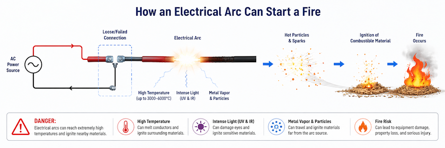
القوس الكهربائي هو تفريغ مستمر للتيار عبر فجوة متأينة بين نقطتين موصلتين. في المفتاح السليم، يمكن أن يحدث قوس قصير جدًا عند فتح نقاط التلامس وعادةً ما يحتويه الجهاز. أما قوس العطل فيختلف: فهو يتطور بشكل غير مقصود عند تلف العزل أو انكسار موصل أو توصيل رديء ويمكن أن يطلق حرارة شديدة بشكل متكرر في المواد القريبة.
جهاز AFDD ذو قيمة لأن بعض الأقواس الخطرة تبقى تحت عتبة تشغيل الأجهزة الوقائية التقليدية. يمكن أن يحدث قوس على التوالي عند طرف فضفاض، موصل مكسور جزئيًا، أو جهة اتصال قابس تالفة. يبقى الحمل على التوالي مع العطل، لذا يمكن لحمل 6 A أن يستمر في سحب التيار الطبيعي تقريبًا بينما يتطور تسخين مكثف في منطقة اتصال صغيرة. حمل 16 A يمكن أن يؤدي إلى تلف سريع إذا لم يتم الكشف عن القوس وإيقاف الدائرة. (MCB) ليس لديه سبب للحمل الزائد للتعثر، وقد لا يرى التجمع المؤرض (RCD) أي اختلال إذا عاد التيار عبر المحايد.
يحدث القوس المتوازي بين موصلات ذات جهود مختلفة. ويمكن أن يتبع عازلاً تضرر بسبب مثبّت، أو سحق، أو رطوبة، أو تعرض للأشعة فوق البنفسجية، أو آفات، أو تقادم حراري. وقد يحد مسار القوس من التيار ويقطعه، مما يمنع القاطع التقليدي من رؤية قصر معدني مستقر. قد يؤدي قوس بين الطور والأرض إلى تشغيل RCD، لكن قوس بين الطور والمحايد يمكن أن يبقى متوازناً من منظور RCD.
تشمل حالات التحذير الشائعة أطراف مقابس مرتخية، وملامسات قوابس متآكلة، وكابلات محصورة خلف الأثاث، وموصلات تضررت أثناء التجريد، وأسلاكاً مرنة تُثنى بشكل متكرر قرب جهاز، وعزلاً اخترقته براغٍ أو مسامير. تبدأ بعض الأعطال كوصلة ذات مقاومة عالية تسخن وتتأكسد قبل ظهور تقوس متقطع. وتتطور أعطال أخرى على طول مسار عزل متفحم بعد الضرر الأصلي. وتفسر هذه الآليات لماذا يظل العزم الصحيح، وتوجيه الكابلات بعناية، والملحقات المناسبة، والفحص الدوري مهمة حتى عند تركيب حماية AFDD.
يمكن للمعدات العادية أيضاً أن تنتج بصمات كهربائية تشبه أجزاءً من موجة القوس. وتعد ملامسات المفاتيح، والمرحلات، والمخفتات، والمحركات ذات الفرش، ومصادر الطاقة ذات الوضع المبدل أمثلة مألوفة. يستخدم AFDD المطابق عدة خصائص للإشارة ومدتها بدلاً من التفاعل مع كل شرارة أو اضطراب عالي التردد. ويدعم هذا التمييز التشغيل العادي مع السماح للجهاز بالاستجابة عندما يفي نمط خطير بمعايير الفصل الخاصة به.
يقوم AFDD بتحليل مستمر للخصائص الكهربائية مثل مدة الانفجار، عدم الانتظام، المكونات عالية التردد، انقطاع التيار، والسلوك حول عبور الصفر للتيار المتردد. يجب أن يميز خوارزميته الأنماط الخطرة عن الأقواس العادية للتبديل، تشغيل المرحل، المخفتات، المحركات ذات الفرشاة، ومزودات الطاقة الإلكترونية. بمجرد استيفاء المعايير المحددة، يأمر آلية الفتح بفصل الدائرة.
يؤدي مبدأ العمل هذا إلى ثلاثة حدود للاختيار:
- إن AFDD ليس مجرد MCB أكثر حساسية. فمقدار التيار والتعرف على نمط القوس مبدآن مختلفان للحماية.
- جهاز AFDD ليس RCD. عتبة تسرب الأرض مثل 30 mA لا تصف الكشف عن القوس.
- لا يمكن لـ AFDD أن يعوض عن موصل أقل من المطلوب، أو قدرة قصر غير كافية، أو نوع RCD خاطئ، أو طرف توصيل رديء.
عملياً، أرسم أولاً وظائف الحماية المطلوبة في مصفوفة: الحمل الزائد، والقصر، والتيار المتبقي، وعطل القوس، والجهد الزائد العابر. ويجب إسناد كل وظيفة مطلوبة إلى جهاز مناسب أو منتج مدمج. وهذا يكشف الحماية الناقصة ويتجنب الدفع مرتين مقابل وظيفة دون فهم التنسيق.
| الجهاز/الوظيفة | الحالة الرئيسية المكتشفة | ما لا يستبدله عموماً |
|---|---|---|
| MCB أو مصهر | الحمل الزائد والتيار الزائد للقصر | كشف التيار المتبقي أو نمط القوس |
| RCCB/RCD | اختلال التيار المتبقي | حماية التيار الزائد ما لم تكن مدمجة تحديداً |
| RCBO | التيار الزائد مع التيار المتبقي | كشف القوس ما لم يكن المنتج صراحة AFDD-RCBO |
| AFDD | بصمات قوس خطرة محددة | وظائف أخرى غير مذكورة في شهادة المنتج |
| SPD | تحديد الجهد الزائد العابر | حماية التيار الزائد، أو التيار المتبقي، أو عطل القوس |
تأكد من مكان انطباق القاعدة قبل اختيار التصنيف
مطابقة المنتج والامتثال للتركيب يجيبان عن أسئلة مختلفة. يحدد معيار المنتج للشركة المصنعة كيفية بناء AFDD واختباره. ويحدد معيار التركيب للمصمم أين تكون التدابير الوقائية مطلوبة أو موصى بها. وتحدد التشريعات الوطنية والجهة ذات الاختصاص القضائي أي إصدار يكون قابلاً للتنفيذ.
مشاريع IEC: استخدم معايير المنتج والتركيب معًا
IEC 62606:2013+A1:2017+A2:2022، الإصدار الموحد 1.2, ينطبق على أجهزة الكشف عن القوس والحماية للاستخدامات المنزلية والمماثلة في دوائر التيار المتردد. يعترف بجهاز يحتوي على وسائل فتح يستخدم مع حماية معلنة، منتج يدمج جهاز حماية آخر، ووحدة كشف قوس منفصلة مركبة مع جهاز حماية معلن. يحدد هذا النطاق عائلة المنتجات؛ ولا يقرر بمفرده كل موقع يجب تركيب AFDD فيه.
يوجد سياق التركيب في معايير مثل IEC 60364-4-42:2024, ، الذي يتناول الحماية من التأثيرات الحرارية. وقد أعادت مراجعته لعام 2024 تنظيم وتوسيع المتطلبات الخاصة بالمواقع التي تكون فيها عواقب الحريق وخيمة. وقد تتبنى المعايير الوطنية المستندة إلى IEC 60364 هذه الأحكام في أوقات مختلفة أو مع تعديلات. لذلك، فإن عبارة “دولة IEC” ليست بيان امتثال كافياً.
سجّل بلد الوجهة، والمعيار الوطني الدقيق وإصداره، وتصنيف الإشغال، وما إذا كانت الدائرة تغذي مآخذ توصيل أو معدات ثابتة، وتصنيفها، وأي استثناءات. إذا كان المنتج مخصصاً لعدة أسواق، فأنشئ مصفوفة أسواق بدلاً من ادعاء عالمي واحد.
المملكة المتحدة: تحكم في انتقال الإصدار
يجب أن تحدد المواصفات البريطانية موقف BS 7671 الحالي. ويذكر مدقق إصدارات IET أن BS 7671:2018+A4:2026 قد نُشر وأن التعديل 3:2024 يظل سارياً حتى 15 أكتوبر 2026. ويجب أن يحدد المشروع المصمم خلال هذه الفترة الانتقالية أي إصدار يشكل الأساس التعاقدي بدلاً من خلط نصوص من مقالات ويب A2 وA3 وA4.
لا تنسخ قائمة “المباني الإلزامية” من مدونة مُركِّب غير مؤرخة. تحقق من اللائحة الحالية والتعريفات ونطاق الدائرة والاستثناءات ومتطلبات المشروع. وقد تبرر معايير العميل أو شركات التأمين أو استراتيجيات الحريق أو تقييم المخاطر الموثق حماية تتجاوز الحد الأدنى للقاعدة الوطنية.
أمريكا الشمالية: حدد AFCI، وليس AFDD عام وفق IEC
في الولايات المتحدة وكندا، المصطلح المعتاد هو قاطع دائرة الأعطال القوسية (AFCI). تحدد UL Solutions معيار UL 1699 لتقييم AFCI في الولايات المتحدة ومعيار CSA C22.2 رقم 270 لكندا. وتشمل منتجات أمريكا الشمالية أشكال قواطع الدائرة والمقابس مع فئات تطبيق محددة.
إن AFDD بقضيب DIN وفق IEC 62606 وAFCI المدرج لدى UL ليسا قابلين للتبادل لمجرد أن كليهما يستجيب للأقواس الكهربائية. فالجهد والتردد وتصنيف الدائرة وإدراج لوحة التوزيع وتوصيل المحايد وبرنامج الاختبار وكود التركيب تختلف. بالنسبة للأعمال في الولايات المتحدة، تحقق أيضاً من إصدار NEC المعتمد محلياً وتعديلاته. بالنسبة للقواطع البديلة، يؤكد دليل علامات UL والتطبيق على تحديد المنتج والتعليمات والتوافق مع لوحة التوزيع المعنية.
اختر بنية الحماية قبل مقارنة نماذج AFDD
يسمح IEC 62606 بعدة أساليب بناء، لكن الكتالوجات قد تصفها بشكل مختلف. والسؤال الهندسي هو أي الوظائف توجد داخل المنتج المختار وأيها يجب أن توفرها أجهزة مرتبطة معلنة.
| البنية | الوظائف الموجودة عادةً | اعتبار الأنسب | خطر التحقق الرئيسي |
|---|---|---|---|
| AFDD مع وسائل فتح | كشف القوس وفتح الدائرة | مشاريع تستخدم جهاز تيار زائد أو تيار متبقي معلن بشكل منفصل | الافتراض بوجود حماية MCB أو RCD عندما لا تكون موجودة |
| AFDD مدمج مع MCB | الحماية من القوس الكهربائي، الحمل الزائد، والدوائر القصيرة | الدوائر التي تكون فيها الحماية من التيار المتبقي منفصلة أو غير مطلوبة | إهمال الحماية المطلوبة بواسطة RCD أو استخدام RCD مشترك غير مناسب |
| دمج AFDD مع RCBO | الحماية من القوس الكهربائي، الحمل الزائد، الدائرة القصيرة، والتيار المتبقي | حماية فردية للدائرة النهائية وفصل أوضح للأخطاء | معاملة جميع تفاصيل RCBO كمعيارية بينما يختلف النوع، الحساسية، المنحنى، والأقطاب |
| وحدة AFD بالإضافة إلى جهاز الحماية المعلن | يعتمد على التوليفة المعتمدة | أنظمة المصنع المصممة للتجميع الميداني | دمج وحدات متوافقة بصريًا لم يتم تقييمها معًا من قبل |
غالبًا ما يكون AFDD-RCBO هو الهيكل الأكثر وضوحًا للدائرة النهائية التي تتطلب حماية إضافية من التيار المتبقي وتخفيف أخطاء القوس. يضيف كشف القوس إلى وظائف الحمل الزائد، الدائرة القصيرة، والتيار المتبقي المرتبطة بـ RCBO. يقتصر هذا الترتيب على فصل التيار المتبقي أو القوس لدائرة واحدة ويقلل من التوصيلات البينية. يجب أن يناسب نوع التيار المتبقي الأحمال، ويجب أن يتوافق منحنى MCB مع ظروف الخطأ والتيار المتدفق، ويجب أن يكون الجهاز متوافقًا مع اللوحة.
مشترك في الأعلى RCCB مع عدة دوائر نهائية AFDD-MCB قد يقلل من تكلفة الجهاز، لكن حدث تيار متبقي واحد يمكن أن يفصل عدة دوائر. يمكن أن يتراكم التسرب من عدة أحمال إلكترونية، ويصبح التشخيص أقل مباشرة. يجب على المصمم مراعاة فقدان الخدمة غير المرغوب فيه، الانتقائية، التسرب الأرضي المسموح به، وأي قاعدة تتطلب حماية فردية.
توفر الوحدات المنفصلة مرونة عندما يعلن المصنع عن التوليفة. لا يؤكد العرض المماثل، اللون المطابق، أو سكة DIN المشتركة بحد ذاتها تنسيق الدائرة القصيرة، اقتران الفصل، أو أداء درجة حرارة الطرف. مشاركة تفاصيل اللوحة والحماية الحالية مع المصنع تسهل تحديد توليفة مناسبة.
حيث توفر حماية AFDD أكبر قيمة
تُستخدم AFDDs بشكل أساسي في الدوائر النهائية حيث قد تتسبب الكابلات التالفة أو الاتصالات الكهربائية المفكوكة في توليد أخطاء قوس كهربائي خطيرة لا يمكن للحماية التقليدية من التيار الزائد أو التيار المتبقي اكتشافها. تعتمد الحاجة إلى حماية AFDD على احتمال تلف الكابل والنتائج المحتملة للحريق.
غرف النوم والمباني التي تحتوي على أماكن نوم
- تُعد غرف النوم، الفنادق، دور الرعاية، مساكن الطلاب، النُزُل، والبيئات المماثلة للنوم من أكثر التطبيقات شيوعًا لـ AFDDs. نظرًا لأن السكان قد لا يلاحظون الرائحة أو الصوت أو العلامات المبكرة للخلل الكهربائي أثناء النوم، توفر AFDDs طبقة حماية إضافية من خلال اكتشاف أخطاء القوس الناتجة عن الاتصالات المفكوكة، الأسلاك التالفة، أو أسلاك الأجهزة المتدهورة.
تعتمد الدوائر الدقيقة التي تتطلب حماية AFDD على اللوائح الكهربائية المحلية ومعايير التركيب. يجب على المصممين أيضًا مراعاة استمرارية الطاقة للأنظمة الطارئة، الإنذارات، والمعدات المتعلقة بالسلامة.
المباني الخشبية والبيئات القابلة للاشتعال
- تقدم المباني ذات الإطار الخشبي، ورش النجارة، الحظائر، مرافق التخزين، والمواقع الأخرى التي تحتوي على مواد قابلة للاشتعال خطر حريق أعلى إذا حدث قوس كهربائي. يمكن لـ AFDDs المساعدة في تقليل هذا الخطر عن طريق قطع أخطاء القوس المتطورة قبل أن تصبح مصدر اشتعال.
يجب أن تكمل حماية AFDD دائمًا - وليس أن تحل محل - التركيب الصحيح للكابلات، الحماية من التيار الزائد، تصميم الحاوية، الفحص الروتيني، وممارسات النظافة الجيدة.
المتاحف، الأرشيفات، والمباني التاريخية
- غالبًا ما تحتوي المتاحف، المكتبات، المعارض، الأرشيفات، والمباني التاريخية على أصول ثقافية أو تاريخية لا يمكن استبدالها. نظرًا لأن الأسلاك الكهربائية قد تكون مخفية خلف الجدران أو يصعب فحصها، يمكن لـ AFDDs دعم استراتيجية الحماية من الحرائق العامة عن طريق تقليل احتمال اشتعال أخطاء القوس.
التجديدات والتركيبات الكهربائية القديمة
- قد تحتوي مشاريع التجديد والتركيبات الكهربائية القديمة على عزل متقدم في العمر، صناديق وصل يصعب الوصول إليها، كابلات تالفة، أو أسلاك تم تعديلها عدة مرات خلال عمر الخدمة. يمكن أن يزيد تلف الكابل الناتج عن الحفر، السحق، الاهتزاز، أو الحركة المتكررة من احتمال حدوث أخطاء قوس.
عندما يحدد الفحص وجود خطر حريق مرتفع، يمكن النظر في حماية AFDD للدوائر النهائية المتأثرة وفقًا لمتطلبات التركيب المحلية.
الدوائر الخارجية والدوائر التي تتعرض للتلف المتكرر
- قد تتعرض الأسلاك الخارجية، المعدات المتحركة، وصلات التمديد، دوائر المقابس في المساحات التي يعاد تكوينها بشكل متكرر، والتركيبات المعرضة للاهتزاز، الرطوبة، القوارض، أو التلف الميكانيكي لاحتمالية أكبر لتدهور الكابل. عندما يكون ذلك مناسبًا، يمكن لـ AFDDs توفير حماية إضافية لهذه الدوائر النهائية، بشرط أن يتطابق الجهاز المختار مع جهد الدائرة، التيار، خصائص الحمل، والظروف البيئية.
مثال تطبيقي
- يقوم سكن الطلاب بتركيب AFDD-RCBOs على دوائر مقابس غرف النوم التي تغذي الشواحن، الحواسيب، السخانات المحمولة، والأجهزة اليومية الأخرى. من خلال توفير حماية من أخطاء القوس، الحمل الزائد، الدائرة القصيرة، والتيار المتبقي لكل دائرة نهائية فردية، يمكن عزل الأعطال بسرعة دون فصل مناطق غير مرتبطة من المبنى.
التطبيقات التي تتطلب حلولًا أخرى لتيار القوس الكهربائي
يجب عدم تطبيق أجهزة AFDD المصممة للتركيبات المنزلية وتركيبات التيار المتردد المماثلة تلقائيًا على مغذيات صناعية ثلاثية الطور، ومخرجات محركات السرعة المتغيرة، ودوائر سلاسل الطاقة الكهروضوئية (PV)، وأنظمة تخزين الطاقة بالبطاريات، أو شبكات التيار المستمر الأخرى. هذه التطبيقات لها خصائص كهربائية مختلفة، وسلوك قوس مختلف، ومعايير منتجات مختلفة، وبالتالي تتطلب أجهزة حماية مخصصة مصممة خصيصًا لتلك الأنظمة.
من المهم أيضًا التمييز AFDDs عن حماية وميض القوس الكهربائي. تهدف أجهزة AFDD إلى الكشف عن أعطال القوس الكهربائي الخطيرة في الدوائر النهائية وقطعها لتقليل خطر الحريق، في حين تركز حماية وميض القوس على حماية الأفراد من أحداث وميض القوس عالية الطاقة في مفاتيح التوزيع الصناعية من خلال تصميم المعدات، وطرق تقليل الطاقة، وإجراءات العمل الآمنة، ومعدات الحماية الشخصية المناسبة (PPE). هاتان التقنيتان تعالجان مخاطر مختلفة ولا ينبغي اعتبارهما قابلة للتبادل.
تجميد المعلمات الكهربائية ومعلمات التجميع
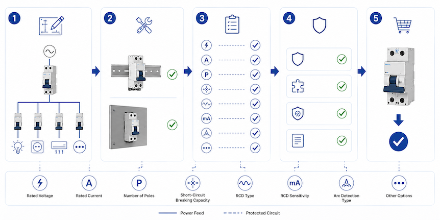
بمجرد تحديد الهيكل، يجب إكمال جدول AFDD مثل أي جدول جهاز حماية هندسي آخر. تمثل كل معلمة شرطًا يجب أن يتحمله الجهاز أو يكتشفه أو يقطعه.
تصنيفات الدائرة: الجهد، التردد، التيار، والأقطاب
تأكيد الجهد الاسمي، نطاق الجهد المسموح به، وتردد الإمداد. تحتاج دائرة الكشف الإلكترونية إلى مصدر طاقة صالح؛ لا يمكن افتراض أن علامة 230 فولت، 50 هرتز مناسبة لـ 120 فولت، 60 هرتز. إذا كان المنتج معلمًا لنطاق، فتأكد من أن جميع الوظائف الوقائية المدمجة تعمل عبر ذلك النطاق.
تحديد ما إذا كانت الدائرة أحادية الطور، خط إلى محايد، خط إلى خط، أو ترتيبات دائرة أخرى. تحقق مما إذا كان الجهاز 1P+N، ذو قطبين، أو تكوين آخر، وأي الأقطاب محمية ومفتوحة. تتطلب بعض المنتجات أطراف خط ومحايد مخصصة أو اتجاه إمداد/تحميل محدد.
التيار المقنن وحماية الموصل. التيار المقنن هو التيار المستمر الذي يمكن لجهاز الحماية تحمله تحت ظروف محددة. يجب أن يفي بالعلاقة التنسيقية المعروفة بين تيار التصميم، تصنيف جهاز الحماية، وقدرة حمل التيار للموصل، مع تطبيق عوامل تصحيح لدرجة حرارة البيئة، التجميع، طريقة التركيب، والعزل الحراري.
افترض أن دائرة نهائية لها تيار تصميم 13 أمبير وقدرة الموصل المصححة 18 أمبير. قد يكون جهاز AFDD-RCBO مدمج بقيمة 16 أمبير مرشحًا لأن تيار التصميم لا يتجاوز تصنيف الجهاز وتصنيف الجهاز لا يتجاوز قدرة الموصل المصححة. لا تنهي هذه الفحوصات البسيطة التصميم: لا تزال هبوط الجهد، وقت الفصل، تيار البدء، سعة الطرف، وتخفيض اللوحة مهمة.
لا تقم بزيادة جهاز AFDD من 16 أمبير إلى 25 أمبير لمجرد إيقاف عمليات الفصل. إذا أظهر مؤشر الفصل زيادة حمل، يجب تصحيح الحمل أو الدائرة. إذا أظهر حدث قوس، فإن تصنيف التيار الأعلى لن يحل توقيع القوس وقد يترك الموصل غير محمي بشكل كافٍ.
منحنى التيار الزائد وسعة القصر
بالنسبة لـ MCB أو RCBO المدمج، يحدد منحنى B أو C أو غيره نطاق التشغيل الفوري للتيار الزائد. يمكن لمنحنى C تحمل تيار بدء أعلى من منحنى B، لكنه يحتاج أيضًا إلى تيار خطأ أعلى للتشغيل الفوري. يجب على المصمم التحقق من وقت الفصل التلقائي المطلوب باستخدام حساب حلقة الخطأ أو القصر المناسب.
المنحنى لا يضبط حساسية AFDD. تغيير المنحنى لمعالجة فصل القوس هو خطأ تصنيفي. استخدم مؤشر الفصل واختبار الدائرة لتحديد الوظيفة التي عملت.
سعة القطع والحماية الاحتياطية. يجب أن تكون سعة القطع المقننة للجهاز كافية للتيار القصر المحتمل في نقطة تركيبه. لا ينبغي اختيار جهاز 6 كيلو أمبير لموقع محسوب بـ 8 كيلو أمبير ما لم يكن هناك ترتيب احتياطي موثق من الشركة المصنعة يزيد القدرة الشرطية تحت الظروف الدقيقة.
عند استخدام الحماية الاحتياطية، سجل طراز الفيوز أو القاطع الأعلى، تصنيفه، التيار المحتمل الأقصى، وجدول التنسيق المطبق. بيان عام مثل "محمي بواسطة MCCB أعلى" غير كافٍ. لا تعوض إلكترونيات AFDD عن التلامسات أو الأطراف المكشوفة التي تتجاوز تصنيفها للقصر.
حساسية التيار المتبقي والنوع
بالنسبة لـ AFDD-RCBO، حدد كل من التيار التشغيلي المتبقي المقنن ونوع RCD. غالبًا ما يرتبط قيمة 30 mA بحماية إضافية، لكن يجب التحقق من القاعدة والدائرة المطبقة. إنها قيمة حساسية، وليست إعداد حماية حريق عالمي.
يحدد نوع RCD أشكال موجات التيار المتبقي التي يمكن للجهاز اكتشافها بشكل صحيح. النوع A يستخدم على نطاق واسع حيث يمكن للمعدات إنتاج تيار متبقي مستمر نابض. الأحمال التي تشمل التحكم في التردد، مكونات التيار المستمر الناعمة، أو إلكترونيات الطاقة المتخصصة قد تتطلب نوعًا آخر وفقًا لتعليمات المعدات والقواعد الوطنية. لا تفترض أبدًا أن كشف القوس يجعل نوع التيار المتبقي غير ذي صلة.
التوافق مع اللوحة، قضيب التوصيل، الطرف، والحرارة
تستحق توافق لوحة التوزيع أكثر من صورة فوتوغرافية. شارك سلسلة اللوحة، السكة، هندسة قضيب التوصيل، موضع الطور، شكل الطرف، عمق الحاوية، عرض الوحدة، الملحقات، والتيار الأقصى للتجميع. يمكن للمورد بعد ذلك التوصية بالتنسيق المناسب وشرح ما إذا كانت هناك حاجة إلى قضيب توصيل جديد، حاوية، أو ترتيب أسلاك.
تحقق من مادة الموصل، نطاق المقطع العرضي، طول التجريد، عزم الشد، عدد الموصلات المسموح بها لكل طرف، ومتطلبات الفيرول. أكد تخفيض درجة الحرارة المحيطة والتجميع. يمكن لصف من أجهزة الحماية الإلكترونية المحملة بشدة أن يعمل بدرجة حرارة أعلى من حالة اختبار الكتالوج المعزولة.
بالنسبة لأعمال التحديث، يجب أن يشمل الفضاء انحناء الموصل والوصول الآمن إلى أزرار الاختبار والمؤشرات. قد يتطلب استبدال RCBO بوحدة واحدة بـ AFDD-RCBO أعرض حاوية جديدة. قد يؤدي نقل الدوائر لتوفير مساحة إلى تغيير توازن الطور، تجميع RCD، توجيه المحايد، والجداول؛ ليست مجرد مسألة ميكانيكية.
مثال تطبيقي: اختيار AFDD لدائرة غرفة ضيوف فندق
يوضح المثال الافتراضي التالي كيفية ارتباط القرارات. ليس تصميمًا عالميًا أو بديلاً لحسابات المشروع. افترض دائرة مأخذ كهربائي أحادية الطور 230 فولت، 50 هرتز لغرفة فندق. تزود الدائرة حمولة قصوى مقدرة 3.0 كيلو واط، تستخدم موصلات نحاسية، تتطلب حماية التيار المتبقي الإضافية 30 mA وفقًا لقواعد المشروع، وتنشأ من لوحة توزيع متوافقة. التيار القصر المحتمل المحسوب عند اللوحة هو 3.4 كيلو أمبير. يتطلب تقييم مخاطر المشروع حماية من أعطال القوس لأن السكان ينامون في المبنى.
الخطوة 1: حساب تيار التصميم.
لهذا التقييم المبسط المكافئ للمقاومة أحادية الطور:
Ib = P / (V × PF)
حيث Ib هي التيار المصمم بالأمبير, P هي القدرة الفعالة بالواط, V هي جهد الدائرة بالفولت, و PF هو معامل القدرة. باستخدام 3000 واط، 230 فولت، ومعامل قدرة إجمالي مفترض 0.95:
Ib = 3,000 / (230 × 0.95) = 13.7 A
وظيفة التيار الزائد 16 أمبير هي نقطة انطلاق معقولة لأن التيار المقنن لها يتجاوز التيار المصمم المحسوب 13.7 أمبير. النتيجة لا تثبت بشكل مستقل أن 16 أمبير صحيحة. لا يزال المصمم بحاجة إلى ملف الحمل الفعلي، قواعد التنوع، متطلبات دائرة المقبس، سلوك التيار اللحظي، وحساب الموصل.
الخطوة 2: تحقق من علاقة الموصل.
افترض أن الكابل المختار له قدرة حمل تيار مدرجة تبلغ 24 أمبير تحت طريقة التثبيت المرجعية الخاصة به. يُفترض أن معامل التصحيح المشترك لدرجة حرارة البيئة، التجميع، والظروف الحرارية هو 0.78. القدرة المصححة للموصل هي:
Iz = It × C = 24 × 0.78 = 18.72 A
حيث Iz هي القدرة المصححة لحمل التيار, It هي القدرة المدرجة, و C هو معامل التصحيح المشترك. العلاقة الأساسية هي:
Ib ≤ In ≤ Iz
في هذا المثال، 13.7 أمبير ≤ 16 أمبير ≤ 18.72 أمبير. تدعم هذه العلاقة وظيفة التيار الزائد المتكاملة 16 أمبير تحت الافتراضات المذكورة. يجب على المهندس التحقق من قواعد التحميل الزائد وفقًا للمعيار المعمول به، هبوط الجهد، أطراف الموصل، ووقت الفصل المطلوب. إذا أدى التجميع لاحقًا إلى تقليل معامل التصحيح، قد لا تتوافق نفس الجهاز والكابل.
الخطوة 3: اختر مجموعة الوظائف.
تحتاج الدائرة إلى حماية من قوس كهربائي، تيار متبقي، حمل زائد، وقصر دائرة. يمكن لـ AFDD مدمج مع RCBO توفير هذه الوظائف الأربع عند أصل الدائرة وتجنب وضع دوائر غرف متعددة خلف RCCB مشترك واحد. يبدأ إدخال الجدول المحتمل بـ "AFDD-RCBO، 1P+N، 230 فولت AC، 50 هرتز، 16 أمبير، 30 mA". يظل الإدخال غير مكتمل حتى يتم تحديد المنحنى، نوع جهاز التيار المتبقي (RCD)، قدرة قصر الدائرة، تبديل النيوترال، ونظام اللوحة.
افترض أن المعدات المتصلة تشمل شواحن الحواسيب المحمولة، مزودات طاقة التلفزيون، وأحمال إلكترونية من الفئة I والفئة II. يختار المصمم نوع RCD من موجات التيار المتبقي المتوقعة وتعليمات المعدات؛ قد يكون النوع A مناسبًا للأحمال الشائعة التي تنتج تيار مستمر نابض، لكن يجب تأكيد هذا الاختيار بدلاً من نسخه من هذا المثال. يتم اختيار منحنى التيار الزائد من ملف التيار اللحظي وحساب حلقة الخطأ، وليس من سلوك AFDD.
الخطوة 4: تحقق من شروط قصر الدائرة والتجميع.
التيار المتوقع لقصر الدائرة المقاس أو المحسوب هو 3.4 kA. يمكن لجهاز بقدرة قصر دائرة مقننة 6 kA أن يتجاوز هذه القيمة، مع مراعاة تصنيف المنتج ذي الصلة، شروط الاختبار، وتصميم اللوحة. جهاز بقدرة 3 kA لن يكون مقبولًا في هذه المرحلة. إذا تم استخدام جهاز حماية علوي لتحقيق تصنيف شرطي أعلى، يجب أن يظهر الزوج الدقيق في بيانات تنسيق الشركة المصنعة.
يجب بعد ذلك التحقق من AFDD-RCBO المقترح مقابل سلسلة لوحات التوزيع الفندقية. يغطي المراجعة رقم جزء قضيب التوصيل والهندسة، جانب الإمداد، توصيل النيوترال، عرض الوحدة، عمق الحاوية، تيار الصف، تخفيض الجهاز المجاور، حجم الطرف، والملحقات المسموح بها. إذا كان الجهاز بعرض وحدتين وكان جدول اللوحة يحتوي على مسار احتياطي واحد فقط، فإن اختيار بديل مدمج غير موثق ليس حلاً هندسيًا. يجب تغيير تخطيط اللوحة أو نظام المنتج المعتمد.
الخطوة 5: أكد تكوين المنتج الكامل.
النتيجة هي مرشح AFDD-RCBO بتيار 16 أمبير لدائرة نهائية 230 فولت، 50 هرتز، 1P+N، مع حماية التيار المتبقي 30 mA وقدرة قصر دائرة لا تقل عن 6 kA تحت ظروف المثال. الخيارات المتبقية هي منحنى التيار الزائد، نوع جهاز التيار المتبقي (RCD)، تبديل النيوترال، عرض الوحدة، توصيل قضيب التوصيل، وصيغة مؤشر الفصل.
توضح هذه الفحوصات النهائية لماذا لا يختار حساب واحد المنتج بأكمله. يدعم حساب التيار تصنيف 16 أمبير لكنه لا يحدد نوع جهاز التيار المتبقي (RCD). تعالج قيمة 6 kA التيار المتوقع لقصر الدائرة لكنها لا تؤكد توافق اللوحة. كل معلمة تجيب على سؤال فني مختلف.
راجع التثبيت كنظام، وليس صفًا من الأجهزة
تؤثر جودة تركيب AFDD مباشرة على الخطر الذي يتم التحكم فيه. يمكن أن تتسبب الأطراف المفكوكة، الموصلات المخدوشة، النيوترالات المختلطة، والحاويات المحمومة في حدوث أعطال أو فصول غير مرغوب فيها. يجب أن يتم العمل بواسطة شخص مؤهل باستخدام العزل الآمن، التحقق من عدم وجود جهد، قواعد الأسلاك المحلية، وتعليمات الشركة المصنعة.
ضع الحماية عند أصل الدائرة النهائية.
يتم تطبيق AFDDs عمومًا عند أصل الدائرة النهائية التي تحميها. يترك جهاز في الأسفل كابلًا علويًا خارج تغطية قوس الكهرباء ما لم تحميه تدابير معتمدة أخرى. لا تفترض أن AFDD واحد عند مدخل لوحة التوزيع يوفر حماية معادلة لكل دائرة نهائية.
تحسين الحماية الفردية للدائرة يحسن أيضًا تحديد موقع العطل والاستمرارية. إذا راقب جهاز علوي واحد العديد من الأحمال غير الخطية، تصبح التوقيعات المجمعة أكثر تعقيدًا ويؤدي الفصل إلى إزالة منطقة أوسع. استخدم فقط التوبولوجيات المسموح بها بتعليمات المنتج ومعيار التثبيت.
احتفظ بكل خط ونيوترال في الدائرة الصحيحة.
النيوترالات المشتركة أو المتقاطعة هي سبب شائع لفصل التيار المتبقي في اللوحات التي تحتوي على وظائف RCBO. يمكنها أيضًا إبطال توقعات العزل. تتبع الدائرة قبل التحويل، حافظ على ارتباط الخط والنيوترال، واتبع أطراف الإمداد والتحميل المحددة.
تتطلب ترتيبات الأسلاك متعددة الأسلاك أو النيوترال المشترك منتجات وطرق توصيل مقبولة خصيصًا لذلك النظام. لا تقسم الموصلات المرتبطة عبر أجهزة أحادية القطب مستقلة بدون التشغيل المشترك المطلوب وموافقة الشركة المصنعة.
إنهاء التحكم والحرارة.
حضّر الموصلات دون قطع الخيوط، أو حبس العزل، أو كشف النحاس الزائد. استخدم أداة عزم معايرة بالقيمة المحددة من الشركة المصنعة. لا تضع موصلين في طرف واحد إلا إذا كان مصممًا وموثقًا لذلك الاستخدام. أعد التحقق من أي توصيل تم إزعاجه أثناء تركيب قضيب التوصيل.
طبق قواعد تخفيض الحاوية والجهاز، خاصة في اللوحات الكاملة، درجات الحرارة المحيطة العالية، أو التركيبات ذات الأحمال المستمرة. إذا حدد المصنع التباعد أو الحد الأقصى للتحميل المجاور، ضمه في مراجعة التخطيط. يمكن أن يتم تطبيق تصنيف ملصق أمامي صحيح بشكل خاطئ تحت ظروف حرارية مختلفة.
احمِ الأحمال الحرجة للاستمرارية عن قصد.
الحماية من الحرائق والاستمرارية هما اعتبارات أمان. يمكن أن يخلق فصل على معدات دعم الحياة، خدمات السلامة، تبريد الأدوية، الإنذارات، أو التحكم في العمليات خطرًا آخر. الجواب ليس حذف الحماية المطلوبة بشكل عشوائي. استخدم القواعد المحلية وتقييم المخاطر الموثق لتحديد فصل الدائرة، الإنذار، الإمدادات البديلة، التكرار، أو تدبير حماية مقبول آخر.
مؤشر الفصل ذو قيمة خاصة حيث يهم وقت الاستعادة. حدد ما إذا كان المنتج يميز بين القوس الكهربائي، التيار المتبقي، التيار الزائد، درجة الحرارة الزائدة، العطل الداخلي، والفتح اليدوي. سلوك المؤشر خاص بالشركة المصنعة؛ أدرج جدول تشغيله في وثائق التسليم.
كيفية اختبار AFDD بعد التثبيت
للتشغيل طبقتان. تختبر اختبارات التركيب القياسية التوصيلات والوظائف الوقائية التقليدية. تتحقق إجراءات المصنع الوظيفية من إلكترونيات AFDD المحددة وسلوك الفتح. لا تستبدل أي من الطبقتين الأخرى.
- افحص: تحقق من الطراز، التصنيفات، علامات الشهادات، الأقطاب، اتجاه الخط/الحمل، النيوترال، تلامس قضيب التوصيل، إعداد الموصل، عزم الشد، الملصقات، وتوافق الحاوية.
- تحقق من الدائرة: أكمل اختبار الاستمرارية، مقاومة العزل، القطبية، اختبار التيار العطل المحتمل أو الحلقة، والاختبارات الأخرى المطلوبة حسب معيار التركيب المحلي.
- اختبر الحماية المدمجة: عند وجود وظيفة RCD، قم بأداء اختبارات RCD المحددة باستخدام أدوات وأساليب مناسبة.
- شغّل وظيفة اختبار AFDD: اتبع تعليمات المنتج ضمن ظروف التغذية والتعامل المحددة. أكد الفتح، الإشارة، وإعادة الضبط.
- طبق حملًا تمثيليًا: تحقق من التشغيل الطبيعي وسجل أي قيود غير معتادة على المعدات يذكرها المصنع.
- وثّق: سجل رقم الجزء الدقيق، الرقم التسلسلي أو الدفعة عند الحاجة، نتائج الاختبار، دليل رمز الفصل، وقيود الاستبدال.
لا تُحدث قوسًا كهربائيًا ميدانيًا بفك طرف، قطع العزل، أو ضرب الموصلات. هذا الاختبار غير آمن ولا يعيد إنتاج اختبار المنتج المعياري. استخدم فقط معدات وإجراءات اختبار معتمدة.
زر الاختبار سهل المبالغة في أهميته. يفحص الوظائف المعرفة بواسطة ذلك المنتج؛ لكنه لا يثبت حالة كل وصلة لاحقة، أو يؤكد عزل الكابل، أو يبرهن على التشغيل لكل قوس ممكن. يبقى الفحص والاختبار الدوري ضروريين.
استخدم سبب الفصل قبل إعادة الضبط
عند فصل AFDD المدمج، حدد الوظيفة التي عملت قبل إعادة ضبطه. بعض الأجهزة تحتفظ بإشارة ميكانيكية؛ وأخرى تعرض تسلسل LED فقط أثناء إجراء إعادة ضبط أو تشغيل محدد. التبديل المتكرر قد يمحو الأدلة المفيدة.
| الحالة الملحوظة | مسار التحقيق المحتمل | اختصار غير آمن يجب تجنبه |
|---|---|---|
| إشارة قوس بعد تشغيل حمل معين | افحص السلك، القابس، المفتاح، التوصيلات الداخلية، المقبس، وإرشادات التوافق | استبدال AFDD بـ MCB دون اختبار الحمل |
| مؤشر التيار المتبقي | تحقق من العزل، المعدات المتصلة، التسرب المتراكم، وتداخل النيوترالات | زيادة حساسية RCD دون مراجعة التصميم |
| إشارة زيادة التيار | قِس الحمل، تحقق من التيار الاندفاعي، الدوائر القصيرة، حماية الموصل، والمنحنى المختار | تركيب تصنيف تيار أعلى لإيقاف الفصل |
| فصل فوري بعد تعديل اللوحة | تحقق من اتجاه الخط/الحمل، ارتباط النيوترال، موقع قضيب التوصيل، وأضرار التوصيل | افتراض أن الجهاز الجديد معطل قبل فحص التركيب |
| إشارة عطل داخلي أو فشل اختبار ذاتي | اتبع تعليمات الاستبدال والضمان من المصنع | تجاوز الوظيفة الإلكترونية بشكل دائم |
إذا لم يتم العثور على عيب مرئي، قم بفصل الأحمال المحمولة وافحص الملحقات المتاحة تحت عزل آمن. أعد توصيل المعدات بشكل منهجي فقط بعد إجراء الاختبارات المطلوبة. بالنسبة للأحمال الإلكترونية غير العادية، زود الشركة المصنعة بنموذج AFDD، رمز الإنتاج، بيانات الدائرة، نموذج الحمل، مؤشر الفصل، والتوقيت. "الفصل العرضي" هو وصف للعرض وليس تشخيصًا.
الأسئلة المتكررة حول اختيار AFDD
هل يحل AFDD محل RCBO؟
فقط المنتج المعتمد صراحةً كـ AFDD مدمج مع RCBO يوفر وظائف القوس الكهربائي، الحمل الزائد، القصر، والتيار المتبقي في وحدة واحدة. لا يوفر AFDD المستقل هذه الوظائف تلقائيًا. اقرأ العلامات، نطاق الشهادة، ونشرة البيانات.
كيف أختار تصنيف التيار لـ AFDD؟
نسق التصنيف مع التيار التصميمي، سعة الموصل المصححة، طريقة التركيب، درجة حرارة البيئة، التجميع، وخصائص الحماية من التيار الزائد المدمجة. لا تختاره بناءً على تصنيف الجهاز المتصل فقط أو تزيده لإخفاء عمليات الفصل غير المبررة.
هل AFDD إلزامي في كل دائرة نهائية؟
لا يوجد قاعدة عالمية تنطبق في كل مكان. يعتمد الجواب على المعيار المعتمد للتركيب، الإصدار، استخدام المبنى، غرض الدائرة وتصنيفها، التعديلات الوطنية، ومتطلبات المشروع. تأكد من الاختصاص القضائي الدقيق قبل إعداد قائمة المواد.
ما الفرق بين AFDD و AFCI؟
يرتبط AFDD عادةً بمعيار IEC 62606 وتركيبات نمط IEC. أما AFCI فهو المصطلح الأمريكي الشمالي المرتبط بمعايير مثل UL 1699 ومتطلبات NEC المحلية. كلاهما يخفف من مخاطر القوس الكهربائي المماثلة ولكنهما ليسا منتجات قابلة للاستبدال تلقائيًا.
هل يمكن لـ AFDD واحد حماية عدة دوائر نهائية؟
لا تفترض ذلك. عادةً ما تُطبق AFDDs عند منشأ الدائرة النهائية، والأجهزة الفردية تحسن تحديد موقع العطل والاستمرارية. يجب أن يكون أي ترتيب مشترك مسموحًا به من قبل المعيار المعمول به وتعليمات الشركة المصنعة.
لماذا يمكن أن يفصل AFDD بينما لا يفصل MCB و RCD؟
يقوم AFDD بتحليل توقيعات القوس بدلاً من الاعتماد فقط على التيار الزائد أو عدم توازن التيار الأرضي. قد يبقى قوس متسلسل عند تيار حمل طبيعي، بينما قد لا يخلق قوس متوازي بين الخط والمحايد أي عدم توازن متبقي. يجب التحقق من مؤشر الفصل لأن المنتج المدمج قد يكون قد عمل لوظيفة أخرى.
القاعدة النهائية لاختيار AFDD
يكون اختيار AFDD جاهزًا للتسعير عندما تكون أربعة أشياء واضحة: تطبيق الدائرة، متطلبات السوق المعمول بها، وظائف الحماية والتصنيفات، وواجهة لوحة التوزيع. إذا كان الاستعلام يذكر فقط "AFDD، 16 A"، فستحتاج الشركة المصنعة إلى مزيد من المعلومات قبل التوصية بالنموذج المناسب.
للمشترين من الشركات، الخطوة الأسهل التالية هي إرسال بلد الوجهة، الجهد والتردد، التيار المقنن، تركيبة الحماية المطلوبة، ترتيب الأقطاب، مستوى القصر، متطلبات التيار المتبقي، تفاصيل اللوحة، الكمية، واحتياجات الشهادة. يمكنك تواصل مع JUTRION بهذه التفاصيل لمناقشة خيارات AFDD المناسبة، مستندات المنتج، العينات، ومتطلبات OEM/ODM.
المراجع الفنية
- IEC 62606 الطبعة الموحدة 1.2 — المتطلبات العامة لأجهزة كشف وحماية أعطال القوس الكهربائي
- IEC 60364-4-42:2024 — الحماية ضد التأثيرات الحرارية
- IET — BS 7671 الطبعة الحالية وفاحص الانتقال
- IET — منشورات BS 7671:2018+A4:2026
- UL Solutions — اختبار وشهادة أجهزة AFCI
- BEAMA — دليل لأجهزة كشف أعطال القوس الكهربائي
