

مفتاح النقل التلقائي لا يتحول إلى المولد؟ الأسباب وتسلسل التشخيص
إجابة سريعة: لماذا لا يقوم مفتاح النقل التلقائي بالتحويل إلى المولد؟
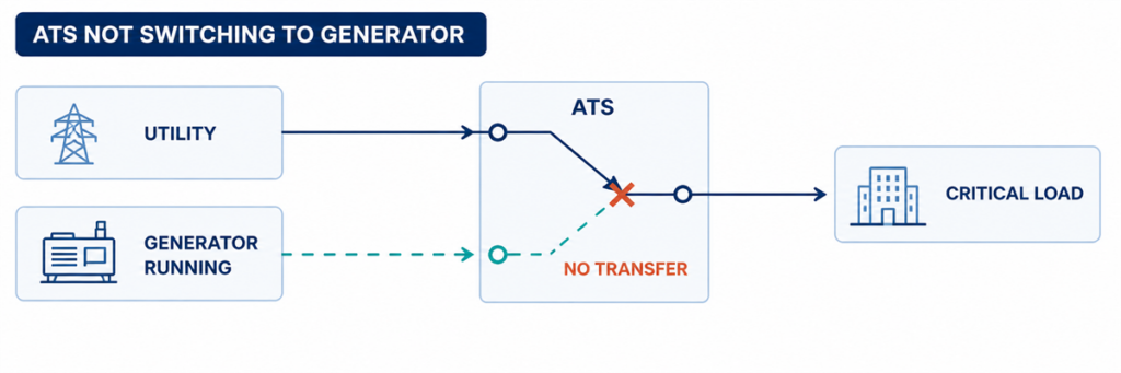
مفتاح النقل التلقائي لا يتحول إلى المولد بينما المولد يعملإذا كان مفتاح النقل التلقائي لا يتحول إلى طاقة المولد، فابحث عن أول خطوة فاشلة في تسلسل النقل. تأكد مما إذا كان ATS قد اكتشف مصدر طاقة غير مقبول، وأصدر أمر تشغيل المحرك، واستقبل جهدًا وترددًا مقبولين من المولد، وأكمل التأخير المبرمج، وشغّل آلية التبديل، وأعاد التغذية الراجعة الصحيحة للموضع. عادةً ما تحدد الحالة المفقودة الأولى منطقة العطل.
تشغيل المولد لا يثبت أن ATS جاهز للنقل. قد يكون قاطع خرج المولد مفتوحًا، أو قد يظل الجهد أو التردد خارج نافذة قبول وحدة التحكم، أو قد يكون هناك طور مفقود، أو قد يكون إدخال الإذن غائبًا، أو قد تفشل الآلية بعد أن تصدر وحدة التحكم الأمر. يصبح استكشاف الأخطاء أسرع عند فحص هذه الشروط بالتسلسل بدلاً من استبدال وحدة التحكم أولاً.
حدود السلامة: يمكن أن يحتوي غلاف ATS على موصلات طاقة حية من الشبكة والمولد في نفس الوقت. يجوز للمشغلين تسجيل المؤشرات والإنذارات وأحداث وحدة التحكم دون فتح الحجرات المكهربة. يجب أن تتبع قياسات الجهد، واختبارات الاستمرارية، والتشغيل اليدوي للآلية، والفحص الداخلي دليل المعدات المرتب، وإجراءات التبديل في الموقع، وقواعد السلامة الكهربائية المعمول بها، ويجب أن يتم تنفيذها فقط بواسطة موظفين مؤهلين.
اقرأ العطل كتسلسل نقل مكسور
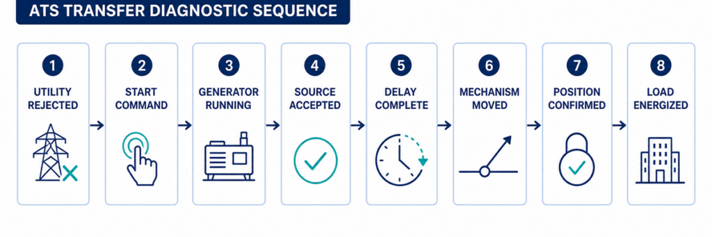
تسلسل تشخيص ATS من فشل الشبكة إلى نقل حمل المولدالنقل التلقائي هو سلسلة من القرارات وليس حركة واحدة. التسلسل النموذجي من الشبكة إلى المولد هو:
- تراقب وحدة التحكم المصدر العادي.
- يصبح المصدر العادي غير مقبول لفترة أطول من تأخير الكشف المبرمج.
- يغير ATS جهة الاتصال الخاصة بتشغيل المحرك لأمر المولد.
- يبدأ المولد ويطور الجهد والتردد عند أطراف المصدر البديل لـ ATS.
- تقبل وحدة التحكم المصدر البديل بعد تأخير الاستقرار.
- تسمح الأقفال المتداخلة والإذونات بأمر النقل.
- تفصل الآلية المصدر العادي وتوصل المصدر البديل وفقًا لتصميم الانتقال.
- تؤكد جهات الاتصال المساعدة الموضع الجديد.
- يظهر الجهد عند أطراف الحمل ويحمل المولد الحمل المنقول.
ابدأ بسجل أحداث وحدة التحكم ومؤشرات المصدر/الموضع على اللوحة الأمامية. اكتب آخر خطوة مؤكدة. إذا لم يتلق المولد أبدًا طلب بدء، فلن يحل فحص جهات اتصال الطاقة المشكلة. إذا أظهرت وحدة التحكم أن المولد متاح لكن الآلية لم تتحرك أبدًا، فلن يحل تغيير إعدادات المولد المشكلة أيضًا.
سجل هذه المعلمات قبل تغيير أي إعداد
المعلمات المفيدة هي القيم التي تحدد ما إذا كانت وحدة التحكم تقبل مصدرًا وتسمح بالحركة. سجل الإعدادات الحالية والقيم المرصودة قبل إجراء أي تغيير. نوافذ القبول ونطاقات التأخير خاصة بوحدة التحكم والمشروع؛ يحدد الجدول ما يجب التقاطه، وليس نقاط الضبط العامة.
| المعلمة | ما يجب تسجيله | لماذا يهم | مصدر الدليل |
|---|---|---|---|
| الجهد الاسمي للمصدر | القيمة الاسمية المكونة وترتيب الأطوار للنظام | التكوين الخاطئ يمكن أن يجعل المصدر السليم يبدو غير مقبول | ملف الإعدادات المعتمد، لوحة الاسم، ومخطط الخط الواحد |
| حدود الجهد المنخفض والجهد الزائد | قيم الالتقاط/الانقطاع أو إعدادات النسبة المئوية لكل مصدر | ينتقل ATS فقط بعد أن يعبر جهد المصدر الحد المطبق والتأخير | قائمة وحدة التحكم وتسلسل التشغيل |
| حدود التردد | قيم قبول التردد المنخفض/المرتفع | قد يتم رفض المولد الجاري تشغيله بينما السرعة غير مستقرة | قائمة وحدة التحكم وبيانات المولد |
| مراقبة الأطوار | وظائف فقدان الطور، تسلسل الأطوار، وعدم توازن الأطوار المفعّلة | حالة طور غير صحيحة واحدة يمكن أن تمنع قبول المصدر | حالة وحدة التحكم والإعدادات |
| تأخير فشل المصدر | الوقت من عدم قبول الشبكة إلى إجراء تشغيل المحرك | يمنع البدء لاضطراب قصير | عرض المؤقت النشط والإعدادات المعتمدة |
| تأخير تثبيت المولد | الوقت بعد أن يصبح المصدر البديل مقبولاً قبل النقل | يسمح للجهد والتردد بالاستقرار | مؤقت وحدة التحكم وسجل الأحداث |
| مهلة النقل والآلية | الوقت المسموح لأمر الفتح/الإغلاق وتأكيد الموضع | تفصل المهلة بين الحركة البطيئة أو الفاشلة والتأخير الطبيعي | رمز الإنذار، سجل الأحداث ودليل المتحكم |
| تأخيرات إعادة النقل والتبريد | وقت التحقق من عودة الشبكة ووقت تشغيل المولد بدون حمل | يشرح سبب بقاء ATS على المولد أو استمرار تشغيل المحرك | إعدادات المتحكم والمولد |
| منطق تلامس بدء المحرك | إغلاق للبدء أو فتح للبدء؛ أرقام الأطراف والحالة الملاحظة | المنطق غير المتوافق يمنع المولد من تلقي الأمر المقصود | مخطط ATS ومخطط بدء المولد عن بُعد |
| مزود التحكم | جهد التحكم AC/DC المقنن والقيمة أثناء الحدث الفاشل | يمكن لانخفاض جهد التحكم إعادة تعيين المتحكم أو إسقاط المشغل | المخطط المرتب والقياس المؤهل |
| مدخلات السماح والمنع | الحالة الطبيعية والحالة أثناء النقل الفاشل | قد يمنع قاطع خارجي الحركة عمدًا | شاشة حالة I/O، سجل PLC/BMS ومخطط الأسلاك |
| تغذية راجعة للموقع | حالات التلامس المفتوح على الوضع الطبيعي، المغلق بديلًا، والموقع الوسيط | قد يأمر المتحكم بشكل صحيح لكنه يفشل في تأكيد الحركة | شاشة I/O للمتحكم ومخطط التلامس المساعد |
| الحالة الملاحظة | منطقة العطل المحتملة | أفضل دليل تالي |
|---|---|---|
| فشل الشبكة؛ لا يبدأ المولد | وضع ATS، الاستشعار، تأخير البدء، تلامس البدء أو أسلاك التحكم | حالة المصدر الطبيعي، المؤقت النشط، مؤشر خرج البدء وحالة وضع التشغيل عن بُعد للمولد |
| يعمل المولد؛ يقول ATS أن المصدر غير متوفر | خرج المولد، القاطع، الجهد/التردد، الطور أو دائرة الاستشعار | مؤشر توفر المولد، قراءات وحدة التحكم والقياس المؤهل عند أطراف المصدر |
| المولد متوفر؛ لا يوجد أمر تحويل | تأخير، تثبيط، سماحية، وضع الاختبار أو منطق التحكم | المؤقت النشط، مدخل التثبيط، الإنذار وسجل الأحداث |
| يظهر أمر التحويل؛ الآلية لا تتحرك | مزود التحكم، المشغل، الملف، المحرك، القفل المتداخل أو العائق الميكانيكي | خرج الأمر، تغذية المشغل وتغذية راجعة للموقع |
| الآلية تتحرك؛ الحمل يبقى غير متصل | فتح قاطع المولد، مسار التلامس التالف، اتصال الخرج أو الحماية المتصلة لاحقاً | موضع ATS، جهد المصدر والحمل، حالات القواطع |
| يحدث التحويل؛ يفصل المولد أو ينهار الجهد | خطوة الحمل، سعة المولد، تيار الاندفاع، إعداد الحماية أو مشكلة الطور | سجل أحداث المولد، التيار، التردد والجهد أثناء التحويل |
تأكيد التعرف على المصدر من فشل الشبكة إلى توفر المولد
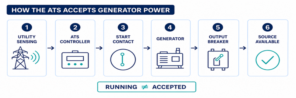
كيف يكتشف ATS ويقبل طاقة المولد قبل التحويلنقطة التحقق 1: هل رفض ATS فعلياً مصدر الشبكة؟
عادةً ما يبقى ATS على الشبكة بينما يعتبر وحدة التحكم هذا المصدر مقبولاً. قد يرى مشغل المنشأة أضواء خافتة، انقطاع جزئي أو فشل لوحة لاحقة بينما تبقى نقاط استشعار الجهد في ATS ضمن حدودها المبرمجة. في هذه الحالة، قد يكون رفض التحويل سلوكاً صحيحاً وليس خطأ في ATS.
تحقق من مؤشر المصدر الطبيعي وقيم وحدة التحكم لكل طور مراقب. قارنها مع وظائف الجهد المنخفض، الجهد العالي، التردد، فقدان الطور وتسلسل الطور المكونة لوحدة التحكم المطلوبة. تحقق أيضاً من تأخير الوقت عند فشل المصدر الطبيعي. قد يختفي اضطراب قصير قبل انتهاء المؤقت، مما يمنع بدء المولد غير الضروري عمداً.
الأسباب الشائعة لقبول وحدة التحكم للشبكة رغم الفشل
- الانقطاع يقع بعد نقطة استشعار ATS.
- فشل دائرة أو مغذي حمل فقط.
- إعداد نقطة التقاط/إسقاط الجهد المنخفض لا يتطابق مع نافذة التشغيل المقصودة.
- صهر استشعار أو خطأ في الأسلاك يعطي وحدة التحكم حالة غير صحيحة.
- وحدة التحكم تقرأ جهد اسمي أو تكوين مصدر خاطئ.
- تأخير فشل المصدر لم ينتهِ بعد.
لا تخفض عتبة الجهد فقط لإجبار التحويل. حدد أولاً حدود جودة المصدر المقصودة وتحقق من تطابق تكوين الاستشعار مع النظام. يمكن أن يسبب الحيادي المفكوك أو الطور المفقود جهوداً خطرة تتطلب تحقيقاً، وليس توسيع نافذة القبول.
نقطة التحقق 2: هل تم إصدار أمر بدء المولد؟
عند رفض المصدر الطبيعي، تعمل العديد من وحدات تحكم ATS من الشبكة إلى المولد على تلامس جاف متصل بدائرة بدء المولد عن بُعد. قد يغلق التلامس للبدء أو يفتح للبدء، حسب تصميم المولد وATS. يجب أن تستخدم الجهازان منطقاً متوافقاً.
تأكد أولاً من أن ATS في AUTO أو وضع التشغيل الطبيعي. يمكن لأوضاع الصيانة، المراقبة، اليدوي، التثبيط، التحكم في الحريق والتمرين أن تمنع التحويل التلقائي أو تغير تسلسل البدء عمداً. سجل الإنذارات النشطة وحالات المدخلات قبل إعادة التعيين؛ قد تمحو إعادة التعيين الأدلة الأكثر فائدة.
إذا أظهرت وحدة التحكم أن خرج البدء قد عمل لكن المولد لا يزال متوقفاً، فافحص الواجهة بين ATS والمولد. الأسباب النموذجية تشمل موصل تحكم مفتوح، استخدام خاطئ لأطراف مفتوحة عادة أو مغلقة عادة، طرف مفكوك، صهر تحكم محترق، وضع المولد عن بُعد معطل، جهد بطارية بدء منخفض أو إنذار إيقاف المولد.
لا ينبغي تركيب وصلة مؤقتة عبر أطراف البدء إلا إذا كانت إجراءات الشركة المصنعة تتطلب ذلك صراحة وكان الاختبار تحت إشراف فنيين مؤهلين. قد يؤدي بدء المولد غير المتوقع إلى تعريض الأشخاص العاملين على المحرك، المولد أو الدائرة اللاحقة للخطر.
نقطة التحقق 3: هل تصل طاقة المولد إلى ATS؟
يمكن للمولد أن يعمل دون أن يزود مفتاح التحويل بأي طاقة قابلة للاستخدام. حالة المحرك وحالة المصدر البديل الكهربائية هما نقطتا فحص منفصلتان.
ابحث عن مؤشر توفر المولد في وحدة التحكم. تحقق مما إذا كان قاطع خرج المولد مغلقًا وما إذا كان هناك أي عازل خارجي أو قاطع تغذية أو فيوز بين المولد وATS مفتوحًا. افحص وحدة تحكم المولد للتحذيرات المتعلقة بزيادة الجهد، انخفاض الجهد، زيادة السرعة، انخفاض السرعة، الإثارة، الطور أو قاطع الدائرة.
عندما يُسمح بالاختبار الحي، يجب على الأفراد المؤهلين قياس المصدر عند أطراف ATS — وليس فقط عند شاشة المولد. أكد صحة جهد الطور إلى الطور، وحيثما ينطبق، جهد الطور إلى النيوترال، التردد واتجاه الطور. قراءة جيدة عند المولد ولكن لا قراءة عند نقاط ATS تشير إلى وجود مشكلة في القاطع الوسيط أو الكابل أو التوصيل أو جهاز الحماية.
لماذا قد يرفض ATS مولدًا يعمل
- يبقى الجهد خارج نطاق القبول المبرمج.
- لم يستقر التردد بعد.
- أحد الأطوار مفقود أو تسلسل الأطوار غير صحيح.
- تم تكوين جهد الوحدة أو نسبة الاستشعار في وحدة التحكم بشكل غير صحيح.
- قاطع المولد مفتوح أو قد تعطل.
- مصهر دائرة الاستشعار أو محول أو حزمة أسلاك مفتوحة.
- يصل المولد إلى ظروف مقبولة لفترة وجيزة فقط ثم ينقطع مرة أخرى.
لا تعامل جهد لوحة المولد بدون حمل كدليل نهائي. القيمة ذات الصلة هي حالة المصدر التي يتعرف عليها ATS، ولاحقًا الجهد والتردد المحتفظ بهما عند تطبيق الحمل.
تتبع أمر التحويل، الآلية وردود فعل الموضع
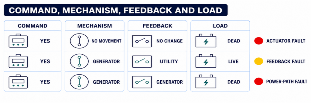
مقارنة تشخيصية لأمر ATS، آلية التبديل، ردود فعل الموضع وجهد الحملنقطة فحص 4: هل هناك مؤقت أو إذن يمنع التحويل؟
حتى بعد قبول المصدر البديل، قد يتأخر التحويل عمدًا. يسمح مؤقت تسخين المولد باستقرار الجهد والتردد. تتطلب تطبيقات أخرى تأكيد تخفيف الحمل، تسلسل المصعد أو المحرك، حالة UPS، إدخال نظام الحريق، إذن العملية أو التفويض عن بُعد قبل تحريك المفتاح.
استخدم شاشة وحدة التحكم لتحديد المؤقت النشط وما إذا كان يعد. قارن الإعداد مع تسلسل التشغيل المعتمد بدلاً من افتراض أن التأخير مفرط. في بعض وحدات التحكم، يمكن لزر اختبار أو وظيفة تجاوز التأخير تقصير تسلسل الاختبار؛ يجب استخدام ذلك فقط وفقًا لإجراء النموذج المحدد وعندما يكون الحمل جاهزًا للتحويل.
إذا انتهى المؤقت ولم يتبع أمر، افحص مدخلات المنطق لمنع التحويل، منع الطوارئ، الفصل الخارجي، تفضيل المصدر، إعادة النقل اليدوية أو تأكيد تخفيف الحمل. يمكن أن يجعل تلامس حقل مشحون دائمًا ATS يبدو معطلاً بينما هو يلتزم بالتشابك المبرمج.
نقطة فحص 5: هل أصدرت وحدة التحكم الأمر للآلية؟
تفصل هذه النقطة بين مشكلة منطقية ومشكلة في المشغل أو مفتاح الطاقة. راجع سجل الأحداث للأوامر مثل فتح الوضع العادي، إغلاق البديل، بدء التحويل أو فشل الإغلاق. قارن الأمر المعروض مع مؤشرات الموضع الفعلية.
إذا لم يصدر أمر رغم أن المصدر وظروف الإذن تبدو صحيحة، تشمل الأسباب المحتملة وجود منع نشط، خطأ في التكوين، إخفاق في الإخراج، مشكلة في طاقة وحدة التحكم أو عطل داخلي في وحدة التحكم. تحقق من إمداد وحدة التحكم والموصلات باستخدام تعليمات الخدمة الخاصة بالشركة المصنعة قبل إدانة وحدة التحكم.
إذا صدر أمر، حدد ما إذا وصل جهد التحكم إلى المحرك المعني، الملف اللولبي، دائرة الفصل السريع، ملف الإغلاق أو ملحق القاطع. تعتمد الدائرة الدقيقة على ما إذا كان ATS يستخدم آلية تبديل مخصصة، قواطع تلامس أو قواطع دوائر بمحرك. لا تطبق مخطط طرفي عام على آلية مختلفة.
نقطة فحص 6: هل يمكن لآلية التبديل إكمال حركتها؟
يمكن لوحدة التحكم إصدار الأمر الصحيح بينما تبقى آلية الطاقة في موضعها السابق أو تتوقف بين المواضع. تشمل الأسباب المحتملة:
- انخفاض أو فقدان جهد تحكم المشغل;
- انفجار فيوز التحكم أو فتح ثانوي محول التحكم;
- تعطل المحرك، الملف اللولبي، ملف الإغلاق أو دائرة الفصل السريع;
- آلية نابض مشحون أو طاقة مخزنة غير جاهزة;
- تشابك كهربائي أو ميكانيكي لم يتم تحريره;
- قاطع دائرة قد انقطع ويتطلب إعادة ضبط قبل الإغلاق;
- تعلق، تلوث، تآكل أو عائق شحن/صيانة;
- مفاتيح حدية أو تلامسات مساعدة غير محاذية أو معطلة.
استمع للأمر وراقب مؤشر الموضع الخارجي المعتمد، لكن لا تقم بتشغيل آلية تتوقف أو تهتز بشكل متكرر. يمكن أن تؤدي الأوامر المتكررة إلى ارتفاع حرارة الملف أو المحرك وتلف التلامسات أو الروابط.
التشغيل اليدوي ليس اختصارًا عاديًا لاستكشاف الأخطاء الحية. تتطلب تعليمات الشركة المصنعة عادةً عزل كل من مصادر المرافق والمولد قبل استخدام المقبض اليدوي. اتبع الإجراء الدقيق للنموذج، تحقق من عدم وجود جهد، واحتفظ بأي احتياطات للطاقة المخزنة.
نقطة فحص 7: هل تتفق ردود فعل الموضع مع مسار الطاقة؟
قد يستخدم المتحكم جهات تلامس مساعدة لإثبات أن مصدرًا واحدًا قد انفتح والآخر أغلق. إذا تحرك الآلية ولكن جهة التلامس المرتدة لم تتغير، يمكن للمتحكم الإبلاغ عن فشل النقل أو حظر الأمر التالي. يمكن أن يسبب قابس فضفاض، أو توصيل خاطئ لجهات التلامس المساعدة، أو فشل الميكروسويتش، أو عدم محاذاة ميكانيكية هذا التفاوت.
قارن بين ثلاث أدلة مستقلة:
- حالة الأمر الصادر من المتحكم؛
- مؤشر الموضع الميكانيكي المعتمد؛
- الحالة الكهربائية عند أطراف الحمل.
يجب أن تتطابق هذه الحالات. إذا قال المتحكم "الحمل على المولد" ولكن أطراف الحمل ظلت بدون جهد، فافحص قاطع المولد، جهات التلامس الكهربائية، وصلات الحافلة، وأجهزة الحماية المتصلة لاحقًا. إذا كان جهد الحمل موجودًا ولكن المتحكم لا يؤكد الموضع، فإن دائرة التغذية الراجعة هي المشتبه به الأقوى.
عندما ينقل ATS الحمل ولكن المولد لا يستطيع حمله
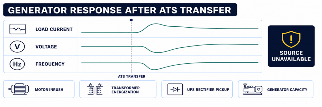
انخفاض جهد وتردد المولد بعد أن يقوم مفتاح النقل التلقائي بنقل الحملبعض الأنظمة تكمل الحركة ثم تعود فورًا، أو تفصل، أو تفقد الجهد. هذا ليس نفس عرض "عدم النقل". إنه يشير إلى أن المصدر البديل أصبح غير مقبول أثناء أو بعد خطوة الحمل، أو أن الحماية قد عملت.
راجع اتجاهات جهد المولد، التردد، والتيار عند لحظة النقل. يمكن أن تتسبب المحركات الكبيرة، والمحولات، ومقومات UPS، والتقاط الأحمال المتزامنة في هبوط الجهد أو انخفاض التردد. قد يفصل قاطع المولد بسبب التحميل الزائد، الدائرة القصيرة، خطأ الأرض، أو إعداد حماية غير صحيح. يمكن أن يسبب عدم توازن الطور أو محايد فضفاض فشل جودة المصدر حتى عندما يبدو إجمالي القدرة بالـ kW معقولًا.
إذا كان الحمل المنقول أو سعة المولد غير مؤكدة، أعد بناء افتراضات التيار والحمل من جدول الحمل المعتمد وبيانات المولد. يوفر JUTRION حاسبة تحديد حجم المولد لنسخ احتياطي ATS حاسبة تحديد حجم المولد لنسخ احتياطي ATS فحصًا أوليًا للحمل التشغيلي وطلب بدء التشغيل. لا يشخص فشل التحكم، ويجب التحقق من نتيجته مقابل بيانات أداء المولد العابرة من الشركة المصنعة.
استخدم اختبارًا وظيفيًا محكمًا لإعادة إنتاج التسلسل
الاختبار المحكم أكثر فائدة من انتظار الانقطاع التالي. حضر الحمل، المولد، والأشخاص المسؤولين، ثم استخدم طريقة الاختبار المحددة لـ ATS المطلوب. يجب أن تتحقق الإجراءات من:
- أن المصدر الطبيعي مقبول في البداية ويحمل الحمل؛
- أن أمر الاختبار يبدأ تسلسل تشغيل المحرك المقصود؛
- أن المولد يصل إلى جهد وتردد مقبولين؛
- أن تأخير النقل المبرمج يعمل؛
- أن الآلية تصل إلى الموضع البديل؛
- أن المولد يحمل الحمل المقصود دون انحراف غير مقبول في الجهد أو التردد؛
- أن تأخير العودة إلى المصدر الطبيعي وإعادة النقل يعمل؛
- أن المولد يكمل فترة التبريد ويتوقف؛
- أن الإنذارات، سجلات الأحداث، المؤشرات عن بُعد، وردود التغذية الراجعة للموضع متوافقة طوال الوقت.
لا تحاكي فشلًا بفصل أسلاك الاستشعار العشوائية أو فتح الحاويات المشحونة. استخدم وظيفة الاختبار المعتمدة من المتحكم أو إجراء اختبار المشروع. تتطلب أنظمة السلامة من الحياة، مضخات الحريق، الطبية، مراكز البيانات، والعمليات المستمرة تنسيقًا قبل أي اختبار نقل.
التقط الأدلة قبل إعادة الضبط أو استبدال الأجزاء
صعُب تشخيص أعطال النقل المتقطعة بعد عودة الطاقة ومسح الإنذارات. التقط الأدلة قبل إعادة ضبط النظام:
- الشركة المصنعة لـ ATS، الطراز، نوع المتحكم، والرقم التسلسلي؛
- جهد المصدر الطبيعي والبديل، التردد، وتكوين الطور؛
- وضع المتحكم ومؤشرات توفر المصدر؛
- رموز الأحداث والإنذارات مع الطوابع الزمنية؛
- التأخير النشط ووقته المتبقي؛
- حالة خرج بدء تشغيل المحرك وحالة وضع التحكم عن بُعد للمولد؛
- موضع قاطع خرج المولد؛
- الموضع المؤمر، الموضع الميكانيكي، وحالة التغذية الراجعة؛
- سواء حدث العطل بدون حمل، أثناء التحويل أو بعد استلام الحمل؛
- الصيانة الأخيرة، تغييرات الإعدادات أو أعمال التوصيل.
يساعد هذا السجل على منع أن يصبح "خطأ المتحكم" التشخيص الافتراضي. كما يسمح للمصنع أو فني الخدمة بتمييز مشكلة ATS عن مشكلة المولد، التوصيل الميداني، الحماية أو الحمل.
استخدم العرض الدقيق للعرض لإدخال نقطة الفحص الصحيحة
"لم يقم ATS بالتحويل" ليس محددًا بما يكفي للتشخيص. سجّل آخر حالة أكملها النظام، ثم أدخل نقطة الفحص المقابلة أعلاه. هذا يمنع خلط أعطال المولد، المتحكم والآلية معًا.
| تقرير العطل | نقطة الفحص الأولى | لا تبدأ بالاستبدال |
|---|---|---|
| المولد لم يبدأ التشغيل | استشعار الشبكة وإشارة بدء المحرك | آلية تبديل الطاقة |
| المولد يعمل، المصدر غير متوفر | خرج المولد عند ATS وإعدادات المصدر | جهات اتصال ATS الرئيسية |
| كلا المصدرين متاحان، لا يوجد أمر | المؤقتات، الوضع، التعطيلات والإذونات | منظم جهد المولد (AVR) |
| الأمر موجود، لا حركة | طاقة التحكم، المشغل والقفل التبادلي | المتحكم الكامل بدون فحوصات الإخراج |
| الحركة موجودة، الحالة خاطئة | جهات الاتصال المساعدة وردود فعل الموضع | المولد |
| التحويل متبوع بالانهيار | الجهد، التردد، التيار وحادث الحماية أثناء التحميل | استشعار ATS قبل مراجعة حادث المولد |
| لا إعادة تحويل إلى الشبكة | قبول الشبكة ومنطق العودة | دائرة بدء تشغيل المولد |
تفسير مؤشرات المتحكم دون اعتبارها قياسات
مؤشرات اللوحة الأمامية هي أول دليل آمن، لكن كل منها يجيب على سؤال محدود. عادةً ما تعني LED "المولد متاح" أن المتحكم قد قبل القيم التي يستشعرها؛ ولا تثبت وجود كل طور عند أطراف الحمل. قد يكون مؤشر "الحمل على المولد" مدفوعًا بجهة اتصال مساعدة؛ ولا يقيس التيار المتدفق إلى الحمل بشكل مستقل.
استخدم المؤشرات لتكوين فرضية اختبار:
- المصدر الطبيعي متاح: يقبل المتحكم المصدر الطبيعي عند مدخلات الاستشعار الخاصة به.
- المولد متاح: توافق جهد وتردد المصدر البديل مع منطق القبول المُكوَّن.
- تشغيل المحرك نشط: أصدر المتحكم أمر بدء التشغيل؛ لا يزال يتطلب تأكيد الأسلاك الميدانية واستجابة المولد.
- مؤقت النقل نشط: المتحكم ينتظر عمدًا، وليس بالضرورة متوقفًا.
- الحمل متصل: تغير إدخال الموضع؛ تحقق من جهد الخرج الفعلي إذا ظل الحمل غير نشط.
- فشل النقل: لم يتم تأكيد الموضع المطلوب ضمن الوقت المسموح.
- المصدر غير متوفر: قيمة مستشعرة خارج نطاق القبول، لكن العرض قد لا يحدد ما إذا كان السبب هو المصدر أو دائرة الاستشعار أو التكوين.
إذا قدم العرض جهد وتردد لكل طور، قارن القيم بقياس مستقل مؤهل عندما يكون ذلك آمنًا ومصرحًا به. يشير اختلاف كبير إلى أسلاك الاستشعار أو الفيوزات أو المحولات أو مقابس الاختيار أو التكوين. الاتفاق مع قيمة خارج النطاق يشير إلى المصدر نفسه.
تحقق من طاقة التحكم قبل لوم المتحكم
شاشة فارغة، إعادة تعيين متقطعة أو فقدان الخرج يمكن أن ينتج عن مشكلة في طاقة التحكم خارج المتحكم الإلكتروني. حسب تصميم ATS، قد تأتي طاقة التحكم من مصدر واحد، أو كلا المصدرين عبر دوائر اختيار، أو محول تحكم، أو مصدر DC، أو وحدة طاقة داخلية.
راجع المخطط الصحيح وحدد أي مصدر يجب أن يغذي المتحكم في كل مرحلة. أثناء انقطاع التيار، يجب أن ينتقل الترتيب الذي يغذي التحكم عادةً من الشبكة إلى مصدر تحكم بديل أو طاقة مخزنة. يمكن أن يتسبب فيوز محترق، نقطة التوصيل الخاطئة في المحول، قابس مفكوك، جهد DC منخفض أو دائرة اختيار فاشلة في إعادة تشغيل المتحكم في الوقت الذي يجب أن ينقل فيه.
تشمل أدلة مشكلة طاقة التحكم:
- إعادة تعيين العرض أو مصابيح LED عند فشل مصدر;
- إعادة بدء الطوابع الزمنية لسجل الأحداث;
- تذبذب المرحلات بدلاً من الثبات;
- بدء حركة المشغل ثم توقفه;
- تشغيل طبيعي في الاختبار اليدوي وفشل أثناء انقطاع المصدر الحقيقي;
- سلوك مختلف عند تحريك باب اللوحة أو حزمة الأسلاك.
قِس جهد التحكم في الحالة التي تحدث فيها العطل، وليس فقط أثناء التشغيل الطبيعي المستقر. أي قياس مباشر يتطلب معدات مناسبة، حدود وصول، وأفراد مؤهلين.
استخدم توقيت الأحداث لاكتشاف فشل النقل المتقطع
يحتاج ATS الذي يعمل أثناء الفحص لكنه فشل أثناء الانقطاع إلى جدول زمني. طابق سجلات مراقب الشبكة، متحكم ATS، متحكم المولد، أجهزة الحماية، BMS أو SCADA، ومعدات الحمل الحرج. حتى المتحكمات التي لا تسجل شكل الموجة تفصيليًا عادةً تحتفظ بترتيب الأحداث الكافي لتحديد الحلقة المفقودة.
يسجل جدول الأحداث المفيد:
- أول خلل في المصدر العادي;
- لحظة إعلان ATS عن عدم توفر المصدر العادي;
- تشغيل خرج بدء المحرك;
- حالة تشغيل المولد ودورانه;
- توفر جهد/تردد المصدر البديل;
- أمر النقل;
- تأكيد فتح المصدر الطبيعي;
- تأكيد إغلاق المصدر البديل;
- استعادة جهد الحمل;
- أي حدث فصل لاحق، إعادة نقل أو حدث عدم توفر المصدر.
التوقيت يكشف الأعطال التي قد تفوتها الفحص الثابت. على سبيل المثال، إذا أصبح المولد متاحًا لمدة ثانيتين ثم اختفى، تحقق من استقراره ومخرجاته. إذا كان أمر النقل وإنذار الفشل في الإغلاق مفصولين بفعل انتهاء مهلة الآلية، تحقق من طاقة المشغل وردود الفعل. إذا أعيد تشغيل وحدة التحكم بين فقدان المصدر العادي وتشغيل المحرك، تحقق من استمرارية طاقة التحكم.
الدلائل البيئية مهمة
سجل ما إذا كانت الأعطال تتزامن مع انخفاض درجة الحرارة، ارتفاع الرطوبة، التكثف، الغبار، الاهتزاز، الحمل الثقيل، عمر البطارية أو فترات الخمول الطويلة. قد تمر الموصلات المتقطعة، الآليات اللاصقة، البطاريات الضعيفة للتشغيل وسخانات الحاوية باختبار دافئ نهاري وتفشل أثناء انقطاع التيار الليلي. الدليل هو الترابط، وليس الافتراض؛ أعد إنتاج الحالة بأمان قبل استبدال الأجزاء.
تمييز عطل ATS عن عطل المولد أو العطل في النظام السفلي
يقع ATS بين مصدرين وحمل، لذا غالبًا ما تُنسب الأعراض إلى المعدات الخاطئة. استخدم الحدود عند أطراف المصدر العادي، أطراف المصدر البديل وأطراف الحمل.
| الأدلة | المنطقة الأكثر احتمالاً | السبب |
|---|---|---|
| عدم وجود إشارة بدء من ATS بعد تأكيد فشل المصدر | استشعار ATS، الوضع، المؤقت أو منطق البدء | لم يُطلب من المولد العمل بعد |
| تغير إشارة البدء؛ المولد لا يدور | الأسلاك الميدانية، إدخال المولد عن بُعد، البطارية أو إنذار المولد | الأمر خرج من ATS |
| شاشة المولد تعرض الجهد؛ أطراف ATS البديلة لا تعرض | قاطع المولد، المغذي أو التوصيل النهائي | فقدان الطاقة بين المولد وATS |
| الجهد البديل يصل إلى ATS؛ وحدة التحكم تقرأ غير متوفر | دائرة الاستشعار، الإعدادات أو إدخال وحدة التحكم | الطاقة موجودة لكنها غير مقبولة |
| المصدر البديل مقبول؛ أمر الإغلاق غائب | منطق ATS، التأخير، المنع أو الإذن | لم يُطلب من الآلية التحرك |
| أمر الإغلاق وطاقة المشغل موجودان؛ لا حركة | المشغل، القفل المتداخل أو الآلية | تم إثبات المنطق وتسليم التحكم |
| أطراف حمل ATS مفعلة؛ اللوحة التالية غير نشطة | قاطع التيار السفلي، الكابل أو نظام الحمل | قام مفتاح النقل بتوصيل الطاقة |
تُحسن هذه الطريقة الحدودية أيضًا التواصل مع الموردين. تقرير يفيد "وجود جهد المولد عند أطراف ATS البديلة، بقاء وحدة التحكم غير متوفرة، فحص الفيوزات والإعدادات" هو تقرير قابل للتنفيذ. أما "ATS لا يعمل" فهو غير ذلك.
تحقق من إعادة النقل وفترة التبريد كجزء من نفس النظام
لا تنتهي سلسلة الأوامر التلقائية الكاملة عندما يصل الحمل إلى طاقة المولد. عند عودة التيار الكهربائي، تتحقق وحدة التحكم عادةً من استمرارية قبوله لفترة تأخير العودة، تنقل الحمل مرة أخرى وتحافظ على تشغيل المولد بدون حمل لفترة تبريد قبل تحرير أمر البدء.
إذا عاد التيار الكهربائي لكن ATS لا يزال على المولد، تحقق من قبول المصدر العادي، تأخير العودة، وضع إعادة النقل اليدوي، تفضيل المصدر ومدخلات المنع الخارجية. في التطبيقات التي يتم فيها الإشراف على العودة عمدًا، قد يتطلب النظام أمر مشغل حتى لو سمح بالنقل التلقائي إلى المولد.
إذا عاد الحمل إلى التيار الكهربائي لكن المولد استمر في التشغيل، حدد ما إذا كان تلامس بدء ATS لا يزال في حالة التشغيل، أو إذا كانت الأسلاك الميدانية قصيرة، أو إذا كان منطق التبريد أو التمرين الخاص بالمولد نشطًا. تجنب تغيير مؤقتات ATS والمولد معًا؛ لأن ذلك يصعب إثبات السبب النهائي.
قم بتكليف السلسلة الكاملة ومنع تكرار الأعطال
تنشأ العديد من حالات فشل النقل عند واجهة المعدات التي تزودها أطراف مختلفة. يجب على مرحلة التشغيل التأكد من سلامة السلسلة الكاملة، وليس فقط تشغيل كل مكون.
تأكيد تعريفات المصدر
تسجيل الجهد الاسمي، التردد، تسلسل الطور، ترتيب النيوترال وتفضيل المصدر. تأكيد اختيارات استشعار المتحكم أو نقاط المحول مقابل النظام الفعلي. التحقق من توافق كلا المصدرين وATS قبل محاولة النقل.
إثبات واجهة بدء المحرك
توثيق ما إذا كان المولد يتوقع منطق الإغلاق للبدء أو الفتح للبدء وأي الأطراف المستخدمة في كلا الطرفين. تأكيد وضع التحكم عن بعد، استمرارية الموصل، والاستجابة لأمر اختبار ATS المعتمد.
إثبات كل مؤقت ومنع
تسجيل تأخير فشل المصدر، تأخير بدء المحرك، استقرار المولد، النقل، العودة وإعدادات التبريد. تشغيل جهات المنع الخارجية، تقليل الحمل وجهات الإذن واحدة تلو الأخرى والتحقق من تطابق إشارة المتحكم مع التسلسل المقصود.
إثبات الوضع والحالة عن بعد
التحقق من مخرجات الاتصال الطبيعي المتصل، الاتصال البديل، توفر المصدر، الإنذار المشترك وفشل النقل على العرض المحلي ونظام المراقبة عن بعد. قد يؤدي تعيين التغذية الراجعة بشكل غير صحيح إلى ظهور ATS سليم على أنه فاشل لنظام إدارة المبنى أو إخفاء فشل حقيقي.
اختبار تحت حمل تمثيلي
إن اختبار الحركة بدون حمل يثبت سلامة الميكانيكا وجزء من سلسلة التحكم، لكنه لا يثبت استجابة المولد لالتقاط الحمل أو أداء مسار التلامس. حيث يسمح إجراء المشروع بذلك، قم بإجراء نقل محمّل تمثيلي وسجّل الجهد والتردد والتيار. قم بتوزيع الأحمال على مراحل عندما يتطلب تسلسل التشغيل المعتمد ذلك.
اترك سجلًا أساسيًا
احفظ الإعدادات وقيم المؤقتات وسجلات الأحداث وقراءات المصدر وأزمنة النقل وحالات التغذية الراجعة للموضع من اختبار ناجح. يمكن للفنيين في المستقبل مقارنة حدث فاشل بهذا التسلسل المعروف بأنه سليم بدلاً من الاعتماد على الذاكرة.
منع عودة نفس عطل عدم النقل
تشغيل النظام الكامل بفاصل زمني مناسب للتطبيق والمتطلبات المحلية، وليس فقط محرك المولد. تشغيل المحرك بدون حمل لا يثبت أن ATS يستشعر، ينقل، يحمل الحمل، يعيد النقل ويتوقف بشكل صحيح.
يجب أن تشمل الصيانة فحص أسلاك التحكم والأطراف والمنصهرات والموصلات وحالة العلبة والسخانات حيث تكون مركبة ومؤشر الموضع والتشغيل الميكانيكي وفق إجراء معزول معتمد وسجلات الأحداث وبطاريات المولد. راجع إعدادات وحدة التحكم بعد تغييرات البرامج الثابتة أو المولد أو المحول أو الحماية أو الحمل.
بالنسبة للمشاريع التي تختار معدات بديلة، تأكد من ترتيب المصدر والجهد والتردد والتيار والأقطاب ومعالجة المحايد وفئة النقل وتنسيق القصر ودخل/خرج وحدة التحكم وحالة العلبة. استخدم JUTRION تحجيم مفتاح التحويل التلقائي JUTRION لفحص تيار الحمل، خطوة تصنيف مناسبة وأسئلة القطب/التكوين الأولية. لا يمكنه اختيار ATS النهائي بدون فحوصات تيار الخطأ، النيوترال، الانتقال والمتحكم.
بعد تأكيد مدخلات المشروع تلك، قارن النتيجة مع مجموعة مفاتيح التحويل التلقائي JUTRION. لا يزال يتعين مطابقة تكوينات فئة PC وفئة CB ووحدة التحكم المتاحة مع المصدر الفعلي والحماية وتسلسل التشغيل.
الأسئلة الشائعة
لماذا يبدأ المولد ولكن لا ينقل ATS؟
قد لا يرى ATS جهد أو تردد المولد مقبولاً، قد يكون قاطع المولد مفتوحًا، قد يكون هناك تأخير استقرار أو منع نشط، أو قد يأمر المتحكم بالنقل بينما يفشل الآلية أو دائرة التغذية الراجعة. تحديد أول حالة مفقودة في تسلسل النقل.
هل يمكنني تحريك ATS يدويًا إلى طاقة المولد؟
فقط وفق إجراء الشركة المصنعة الخاص بالطراز. تتطلب العديد من مفاتيح التحويل فصل كلا المصدرين قبل التشغيل اليدوي. لا تستخدم أبدًا المقبض اليدوي كاختصار لاستكشاف الأعطال أثناء وجود التيار.
لماذا ينقل ATS ثم يعود فورًا؟
قد يخرج مصدر المولد عن نافذة قبول الجهد أو التردد عند تطبيق الحمل، أو قد يعمل قاطع/حماية المولد. افحص سجل الأحداث وسلوك المولد أثناء خطوة الحمل.
هل يمكن لإعداد تأخير زمني غير صحيح أن يمنع ATS من النقل؟
نعم. يمكن لتأخيرات فشل المصدر وبدء المحرك واستقرار المولد والنقل أن تجعل تسلسلًا صحيحًا يبدو متوقفًا. يمكن للمنع النشط أو الإذن أيضًا أن يحجب النقل بعد انتهاء المؤقت.
هل تعني شاشة متحكم ATS فارغة أن المفتاح الكامل قد فشل؟
ليس بالضرورة. يمكن أن يؤدي فقدان طاقة وحدة التحكم أو منصهر تحكم مفتوح أو مشكلة في المحول أو الحزام إلى إطفاء الشاشة. تحقق من مسار طاقة التحكم وفق إجراء الخدمة الخاص بالشركة المصنعة قبل استبدال وحدة التحكم.
أنهِ التشخيص عند أول حالة مفقودة
لا تبدأ بالمكوّن الأغلى ثمنًا. ابدأ بالتسلسل. إذا لم يرفض مفتاح التحويل التلقائي (ATS) مصدر الكهرباء الرئيسي أبدًا، فافحص الاستشعار والإعدادات. إذا رفض مصدر الكهرباء الرئيسي لكنه لم يطلب بدء التشغيل أبدًا، فافحص الوضع والمؤقتات ودائرة بدء التشغيل. إذا كان المولد يعمل لكنه يظل غير متاح، فافحص خرجه الكهربائي ومسار الاستشعار في مفتاح التحويل التلقائي (ATS). إذا تم قبول المصدر لكن المفتاح لا يتحرك، فافحص الشروط المسموحة وطاقة التحكم والمشغّل والتعشيقات. إذا تحركت الآلية لكن الحمل يظل ميتًا، فتحقق من مسار الطاقة والتغذية الراجعة.
هذا الترتيب القائم على الأدلة يقلل زمن التوقف ويتجنب استبدال وحدة التحكم بسبب قاطع المولد، أو استبدال الآلية بسبب منع نشط، أو استبدال مفتاح تحويل تلقائي (ATS) كامل بسبب موصل تحكم واحد مفتوح.
المراجع الفنية
