

¿El interruptor de transferencia automática no cambia a generador? Causas y secuencia de diagnóstico
Respuesta rápida: ¿Por qué el interruptor de transferencia automática no conmuta al generador?
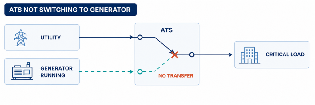
Interruptor de transferencia automática no conmuta al generador mientras el generador está en marchaSi un interruptor de transferencia automática no conmuta a la energía del generador, localice el primer paso fallido en la secuencia de transferencia. Confirme si el ATS detectó una fuente de red inaceptable, emitió la orden de arranque del motor, recibió voltaje y frecuencia aceptables del generador, completó su retardo programado, operó el mecanismo de conmutación y devolvió la señal de posición correcta. El primer estado ausente normalmente identifica el área de la falla.
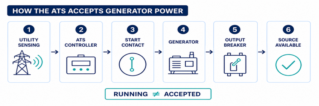
Un generador en marcha no prueba que el ATS esté listo para transferir. El interruptor de salida del generador puede estar abierto, el voltaje o la frecuencia pueden permanecer fuera de la ventana de aceptación del controlador, puede faltar una fase, puede faltar una entrada permisiva o el mecanismo puede fallar después de que el controlador emite la orden. La resolución de problemas es más rápida cuando estas condiciones se verifican en secuencia en lugar de reemplazar primero el controlador.
Límite de seguridad: una envolvente ATS puede contener conductores vivos de la red y del generador al mismo tiempo. Los operadores pueden registrar indicadores, alarmas y eventos del controlador sin abrir compartimentos energizados. Las mediciones de voltaje, pruebas de continuidad, operación manual del mecanismo e inspección interna deben seguir el manual ordenado del equipo, el procedimiento de conmutación del sitio y las normas aplicables de seguridad eléctrica, y deben ser realizadas solo por personal cualificado.
Interprete la falla como una secuencia de transferencia interrumpida
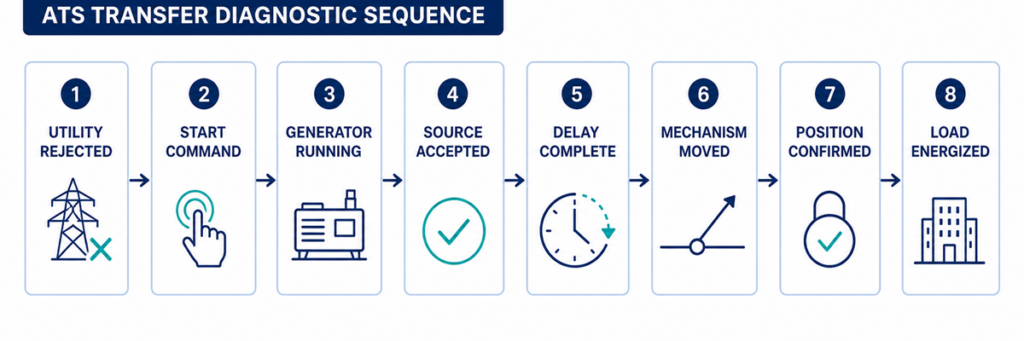
Secuencia de diagnóstico ATS desde fallo de la red hasta transferencia de carga al generadorUna transferencia automática es una cadena de decisiones más que un solo movimiento. Una secuencia típica de red a generador es:
- El controlador supervisa la fuente normal.
- La fuente normal se vuelve inaceptable durante más tiempo que el retardo de detección programado.
- El ATS cambia su contacto de arranque del motor para comandar el generador.
- El generador arranca y desarrolla tensión y frecuencia en los terminales de fuente alterna del ATS.
- El controlador acepta la fuente alterna tras su retardo de estabilización.
- Los enclavamientos y permisos permiten una orden de transferencia.
- El mecanismo desconecta la fuente normal y conecta la fuente alterna según su diseño de transición.
- Los contactos auxiliares confirman la nueva posición.
- Aparece tensión en los terminales de carga y el generador soporta la carga transferida.
Comience con el registro de eventos del controlador y los indicadores de fuente/posición del panel frontal. Anote el último paso confirmado. Si el generador nunca recibe una orden de arranque, inspeccionar los contactos de potencia no resolverá el problema. Si el controlador muestra el generador como disponible pero el mecanismo nunca se mueve, cambiar los ajustes del generador tampoco lo solucionará.
Registre Estos Parámetros Antes de Cambiar un Ajuste
Los parámetros útiles son los valores que determinan si el controlador acepta una fuente y permite el movimiento. Registre los ajustes actuales y los valores observados antes de realizar cualquier cambio. Las ventanas de aceptación y los rangos de retardo son específicos del controlador y del proyecto; la tabla identifica qué capturar, no puntos de ajuste universales.
| Parámetro | Qué registrar | Por qué es importante | Fuente de evidencia |
|---|---|---|---|
| Voltaje nominal de la fuente | Valor nominal configurado y disposición de fases del sistema | Una configuración incorrecta puede hacer que una fuente sana parezca inaceptable | Archivo de ajustes aprobado, placa de características y esquema unifilar |
| Límites de subtensión y sobretensión | Valores de disparo/desconexión o ajustes porcentuales para cada fuente | El ATS transfiere solo después de que la tensión de la fuente cruce el límite y retardo aplicables | Menú del controlador y secuencia de operación |
| Límites de frecuencia | Valores de aceptación de subfrecuencia/sobrefrecuencia | Un generador en marcha puede ser rechazado mientras la velocidad es inestable | Menú del controlador y datos del generador |
| Supervisión de fases | Funciones de pérdida de fase, secuencia de fases y desequilibrio de fases habilitadas | Una condición incorrecta de fase puede bloquear la aceptación de la fuente | Estado y ajustes del controlador |
| Retardo por fallo de fuente | Tiempo desde que la red es inaceptable hasta la acción de arranque del grupo electrógeno | Evita el arranque por una perturbación breve | Visualización del temporizador activo y ajustes aprobados |
| Retardo de estabilización del generador | Tiempo tras la aceptación de la fuente alternativa antes de la transferencia | Permite que el voltaje y la frecuencia se estabilicen | Temporizador del controlador y registro de eventos |
| Tiempo de espera para transferencia y mecanismo | Tiempo permitido para la orden de apertura/cierre y confirmación de posición | Un tiempo de espera separa el movimiento lento o fallido del retardo normal | Código de alarma, registro de eventos y manual del controlador |
| Retrasos de retransferencia y enfriamiento | Tiempo de verificación de retorno de la red y tiempo de funcionamiento del generador sin carga | Explica por qué el ATS permanece en generador o por qué el motor sigue funcionando | Ajustes del controlador y del generador |
| Lógica de contacto de arranque del motor | Cerrar para arrancar o abrir para arrancar; números de terminal y estado observado | Lógica incompatible impide que el generador reciba la orden prevista | Esquema del ATS y diagrama de arranque remoto del generador |
| Alimentación de control | Tensión nominal de control AC/DC y valor durante el evento fallido | Una caída de tensión de control puede reiniciar el controlador o soltar el actuador | Esquema ordenado y medición cualificada |
| Entradas permisivas y de inhibición | Estado normal y estado durante la transferencia fallida | Un contacto externo puede bloquear intencionadamente el movimiento | Pantalla de estado I/O, registro PLC/BMS y diagrama de cableado |
| Retroalimentación de posición | Estados de contacto normalmente abierto, alternativo cerrado y posición intermedia | El controlador puede ordenar correctamente pero no confirmar el movimiento | Pantalla I/O del controlador y diagrama de contacto auxiliar |
| Estado observado | Área probable de fallo | Mejor siguiente evidencia |
|---|---|---|
| Fallo de la red; el generador no arranca | Modo ATS, detección, retardo de arranque, contacto de arranque o cableado de control | Estado de la fuente normal, temporizador activo, indicación de salida de arranque y estado de modo remoto del generador |
| El generador funciona; el ATS indica fuente no disponible | Salida del generador, interruptor, voltaje/frecuencia, fase o circuito de detección | Indicador de generador disponible, lecturas del controlador y medición cualificada en terminales de fuente |
| Generador disponible; sin orden de transferencia | Retardo, inhibición, permiso, modo de prueba o lógica de control | Temporizador activo, entrada de inhibición, alarma y registro de eventos |
| Aparece orden de transferencia; el mecanismo no se mueve | Alimentación de control, actuador, bobina, motor, enclavamiento u obstrucción mecánica | Salida de orden, alimentación del actuador y retroalimentación de posición |
| El mecanismo se mueve; la carga permanece sin tensión | Interruptor del generador abierto, camino de contacto dañado, conexión de salida o protección aguas abajo | Posición del ATS, voltaje de fuente y carga, estados del interruptor |
| Se produce la transferencia; el generador se desconecta o colapsa el voltaje | Paso de carga, capacidad del generador, corriente de irrupción, ajuste de protección o problema de fase | Registro de eventos del generador, corriente, frecuencia y voltaje durante la transferencia |
Confirmar reconocimiento de fuente desde fallo de red hasta disponibilidad del generador
Cómo un ATS detecta y acepta la potencia del generador antes de transferirPunto de control 1: ¿Rechazó realmente el ATS la fuente de red?
El ATS normalmente permanece en la red mientras el controlador considera esa fuente aceptable. Un operador de la instalación puede observar luces tenues, un corte parcial o una falla en un cuadro aguas abajo mientras los puntos de detección de voltaje en el ATS permanecen dentro de sus límites programados. En ese caso, negarse a transferir puede ser un comportamiento correcto y no una falla del ATS.
Verifique el indicador de fuente normal y los valores del controlador para cada fase monitorizada. Compárelos con las funciones configuradas de subtensión, sobretensión, frecuencia, pérdida de fase y secuencia de fases para el controlador solicitado. También compruebe el retardo temporal ante fallo de fuente normal. Una perturbación breve puede desaparecer antes de que expire ese temporizador, evitando deliberadamente un arranque innecesario del generador.
Razones comunes por las que el controlador aún acepta la red
- El corte está aguas abajo del punto de detección del ATS.
- Solo ha fallado un circuito o alimentador de carga.
- El ajuste de conexión/desconexión por subtensión no coincide con la ventana de operación prevista.
- Un fusible de detección o un fallo en el cableado proporciona al controlador un estado incorrecto.
- El controlador está leyendo un voltaje nominal o configuración de fuente incorrectos.
- No ha expirado el retardo por fallo de fuente.
No reduzca un umbral de voltaje simplemente para forzar la transferencia. Primero establezca los límites de calidad de fuente previstos y verifique que la configuración de detección coincida con el sistema. Un neutro suelto o una fase ausente pueden crear voltajes peligrosos que requieren investigación, no una ventana de aceptación más amplia.
Punto de control 2: ¿Se emitió la orden de arranque del generador?
Cuando se rechaza la fuente normal, muchos controladores ATS de red a generador accionan un contacto seco conectado al circuito de arranque remoto del generador. El contacto puede cerrarse para arrancar o abrirse para arrancar, dependiendo del diseño del generador y del ATS. Ambos dispositivos deben usar lógica compatible.
Primero confirme que el ATS está en AUTO o en su modo normal de operación. Los modos de mantenimiento, monitorización, manual, inhibición, control de incendios y ejercicio pueden bloquear intencionadamente la transferencia automática o cambiar la secuencia de arranque. Registre las alarmas activas y los estados de entrada antes de reiniciar cualquier cosa; un reinicio puede borrar la evidencia más útil.
Si el controlador muestra que la salida de arranque ha operado pero el generador permanece detenido, inspeccione la interfaz entre el ATS y el generador. Las causas típicas incluyen conductor de control abierto, uso incorrecto de terminales normalmente abiertos o normalmente cerrados, terminal suelto, fusible de control fundido, modo remoto del generador deshabilitado, bajo voltaje de batería de arranque o alarma de parada del generador.
No se debe improvisar un puente entre terminales de arranque a menos que el procedimiento del fabricante lo requiera explícitamente y la prueba sea controlada por personal cualificado. Un arranque inesperado del generador puede exponer a personas que trabajan en el motor, alternador o circuito aguas abajo.
Punto de control 3: ¿Está llegando potencia del generador al ATS?
Un generador puede estar funcionando sin suministrar potencia útil al interruptor de transferencia. El estado del motor y el estado eléctrico de la fuente alternativa son puntos de control separados.
Busque la indicación de generador disponible en el controlador. Verifique si el interruptor de salida del generador está cerrado y si algún aislador externo, interruptor de alimentación o fusible entre el generador y el ATS está abierto. Inspeccione el controlador del generador para alarmas de sobretensión, subtensión, sobrevelocidad, subvelocidad, excitación, fase o disparo del interruptor.
Cuando se autorice la prueba en vivo, el personal cualificado debe medir la fuente en los terminales del ATS, no solo en la pantalla del generador. Confirme las tensiones correctas entre fases y, cuando corresponda, entre fase y neutro, la frecuencia y la rotación de fase. Una buena lectura en el alternador pero ninguna en el ATS indica un problema en el interruptor, cable, terminación o dispositivo de protección intermedio.
Por qué el ATS puede rechazar un generador en funcionamiento
- La tensión permanece fuera de la banda de aceptación programada.
- La frecuencia no se ha estabilizado.
- Falta una fase o la secuencia de fases es incorrecta.
- El voltaje nominal o la relación de detección del controlador están configurados incorrectamente.
- El interruptor del generador está abierto o se ha disparado.
- Un fusible, transformador o arnés de detección está abierto.
- El generador alcanza condiciones aceptables solo brevemente y vuelve a caer.
No considere la tensión del panel sin carga del generador como prueba definitiva. El valor relevante es la condición de la fuente reconocida por el ATS y, posteriormente, la tensión y frecuencia mantenidas cuando se aplica la carga.
Rastree el Comando de Transferencia, el Mecanismo y la Retroalimentación de Posición
Comparación diagnóstica del comando ATS, mecanismo de conmutación, retroalimentación de posición y tensión de cargaPunto de control 4: ¿Un temporizador o permiso está reteniendo la transferencia?
Una vez que la fuente alternativa es aceptable, la transferencia puede retrasarse intencionadamente. Un temporizador de calentamiento del generador permite estabilizar tensión y frecuencia. Otras aplicaciones requieren confirmación de reducción de carga, secuencia de ascensor o motor, estado del UPS, entrada del sistema contra incendios, permiso de proceso o autorización remota antes de que el interruptor se mueva.
Use la pantalla del controlador para identificar qué temporizador está activo y si está contando. Compare la configuración con la secuencia de operación aprobada en lugar de asumir que un retraso es excesivo. En algunos controladores, un botón de prueba o función de omisión de retraso puede acortar una secuencia de prueba; esto debe usarse solo bajo el procedimiento específico del modelo y cuando la carga esté lista para transferirse.
Si el temporizador finaliza pero no sigue ningún comando, inspeccione las entradas lógicas para inhibición de transferencia, inhibición de emergencia, disparo externo, preferencia de fuente, retransferencia manual o confirmación de reducción de carga. Un contacto de campo permanentemente energizado puede hacer que el ATS parezca defectuoso mientras obedece el enclavamiento programado.
Punto de control 5: ¿El controlador ordenó al mecanismo?
Este punto de control separa un problema lógico de un problema del actuador o del conmutador de potencia. Revise el registro de eventos para comandos como abrir normal, cerrar alternativo, transferencia iniciada o fallo al cerrar. Compare el comando mostrado con los indicadores reales de posición.
Si no se produjo ningún comando aunque las condiciones de fuente y permiso parezcan correctas, las causas posibles incluyen una inhibición activa, error de configuración, salida fallida, problema de alimentación del controlador o fallo interno del controlador. Verifique la alimentación y los conectores del controlador usando las instrucciones de servicio del fabricante antes de condenar el controlador.
Si se produjo un comando, determine si la tensión de control llegó al motor, solenoide, bobina de cierre, disparo por derivación o accesorio del interruptor correspondiente. El circuito exacto depende de si el ATS usa un mecanismo de conmutación dedicado, contactores o interruptores automáticos motorizados. No aplique un diagrama genérico de terminales a un mecanismo diferente.
Punto de control 6: ¿Puede el mecanismo de conmutación completar su movimiento?
Un controlador puede emitir el comando correcto mientras el mecanismo de potencia permanece en su posición anterior o se detiene entre posiciones. Las causas posibles incluyen:
- tensión de control del actuador ausente o baja;
- fusible de control fundido o secundario del transformador de control abierto;
- motor, solenoide, bobina de cierre o circuito de disparo por derivación fallados;
- mecanismo de resorte cargado o energía almacenada que no está listo;
- un enclavamiento eléctrico o mecánico que no se ha liberado;
- interruptor que se ha disparado y requiere reinicio antes de cerrar;
- atasco, contaminación, corrosión u obstrucción por transporte/mantenimiento;
- interruptores de límite y contactos auxiliares desalineados o fallados.
Escuche el comando y observe la indicación externa de posición aprobada, pero no accione repetidamente un mecanismo que se atasca o vibra. Los comandos repetidos pueden sobrecalentar una bobina o motor y dañar contactos o enlaces.
La operación manual no es un atajo habitual para la resolución de problemas en vivo. Las instrucciones del fabricante comúnmente requieren que tanto la fuente de red como la del generador estén aisladas antes de usar una maneta manual. Siga el procedimiento exacto para el modelo, verifique la ausencia de tensión y respete las precauciones por energía almacenada.
Punto de control 7: ¿Coincide la retroalimentación de posición con la trayectoria de potencia?
El controlador puede utilizar contactos auxiliares para verificar que una fuente se abrió y la otra se cerró. Si el mecanismo se mueve pero el contacto de retroalimentación no cambia, el controlador puede informar una transferencia fallida o bloquear el siguiente comando. Un enchufe flojo, un cableado incorrecto de los contactos auxiliares, un microswitch defectuoso o un desalineamiento mecánico pueden crear esta discrepancia.
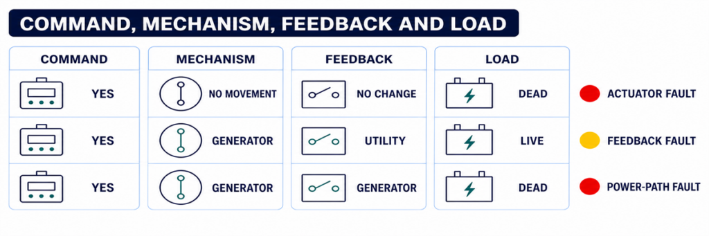
Compare tres evidencias independientes:
- el estado ordenado por el controlador;
- el indicador mecánico de posición aprobado;
- el estado eléctrico en los terminales de carga.
Estos estados deben coincidir. Si el controlador indica “carga en generador” pero los terminales de carga permanecen sin tensión, investigue el interruptor del generador, los contactos de potencia, las conexiones del bus y los dispositivos de protección aguas abajo. Si hay tensión en la carga pero el controlador no confirma la posición, el circuito de retroalimentación es el principal sospechoso.
Cuando el ATS Transfiere pero el Generador No Puede Mantener la Carga
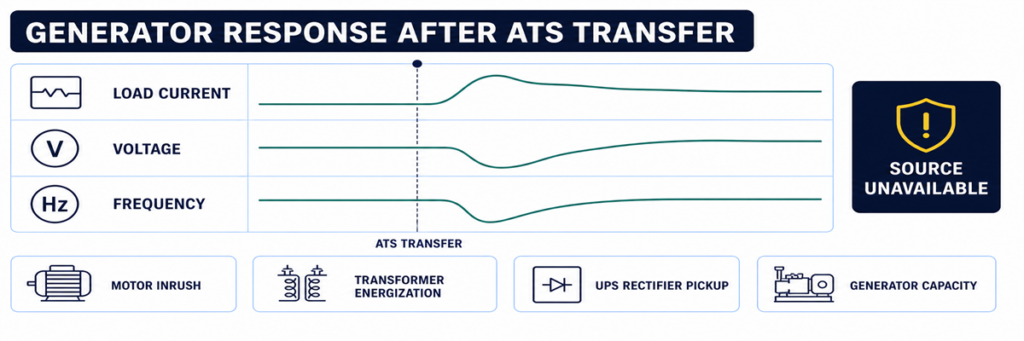
Caída de tensión y frecuencia del generador tras una transferencia automática de cargaAlgunos sistemas completan el movimiento y luego regresan inmediatamente, disparan o pierden tensión. Ese no es el mismo síntoma que “no transferencia”. Indica que la fuente alternativa se volvió inaceptable durante o después del paso de carga, o que la protección actuó.
Revise las tendencias de tensión, frecuencia y corriente del generador en el instante de la transferencia. Motores grandes, transformadores, rectificadores de UPS y la conexión simultánea de cargas pueden causar caída de tensión o decaimiento de frecuencia. Un interruptor del generador puede dispararse por sobrecarga, cortocircuito, falla a tierra o un ajuste incorrecto de protección. Un desequilibrio de fases o un neutro flojo pueden generar una falla en la calidad de la fuente incluso cuando el total de kW parece razonable.
Si la carga transferida o la capacidad del generador son inciertas, reconstruya las suposiciones de corriente y carga a partir del programa de carga aprobado y los datos del generador. La calculadora de dimensionamiento de generadores JUTRION para respaldo ATS proporciona una verificación inicial de la carga en funcionamiento y la demanda de arranque. No diagnostica una falla de control, y su resultado debe verificarse con los datos de rendimiento transitorio del fabricante del generador.
Utilice una Prueba Funcional Controlada para Reproducir la Secuencia
Una prueba controlada es más útil que esperar el próximo corte. Prepare la carga, el generador y el personal responsable, luego utilice el método de prueba especificado para el ATS solicitado. El procedimiento debe verificar:
- la fuente normal es inicialmente aceptable y está suministrando la carga;
- el comando de prueba inicia la secuencia de arranque del motor prevista;
- el generador alcanza tensión y frecuencia aceptables;
- se opera el retardo programado de transferencia;
- el mecanismo alcanza la posición alternativa;
- el generador soporta la carga prevista sin desviaciones inaceptables de tensión o frecuencia;
- se operan el retorno a la fuente normal y el retardo de retransferencia;
- el generador completa su periodo de enfriamiento y se detiene;
- las alarmas, registros de eventos, indicaciones remotas y retroalimentación de posición coinciden durante todo el proceso.
No simule una falla desconectando cables de detección arbitrarios o abriendo compartimentos energizados. Utilice la función de prueba aprobada del controlador o el procedimiento de prueba del proyecto. Los sistemas de seguridad vital, bombas contra incendios, médicos, centros de datos y procesos continuos requieren coordinación antes de cualquier prueba de transferencia.
Capture la evidencia antes de restablecer o reemplazar piezas
Las fallas intermitentes de transferencia son difíciles de diagnosticar después de que la alimentación ha regresado y las alarmas se han borrado. Capture evidencia antes de restablecer el sistema:
- fabricante del ATS, modelo, tipo de controlador y número de serie;
- tensión, frecuencia y configuración de fases de la fuente normal y alternativa;
- modo del controlador e indicadores de fuente disponible;
- códigos de eventos y alarmas con marcas de tiempo;
- retardo activo y tiempo restante;
- estado de salida de arranque del motor y estado remoto del generador;
- posición del interruptor de salida del generador;
- posición ordenada, posición mecánica y estado de retroalimentación;
- si la falla ocurrió sin carga, durante la transferencia o después de la conexión de la carga;
- mantenimiento reciente, cambios de configuración o trabajos de cableado.
Este registro evita que “fallo del controlador” se convierta en el diagnóstico predeterminado. También permite que un fabricante o técnico de servicio distinga un problema del ATS de un problema del generador, cableado de campo, protección o carga.
Utilice el Síntoma Exacto para Ingresar el Punto de Control Correcto
“El ATS no transfirió” no es lo suficientemente específico para el diagnóstico. Registre el último estado que completó el sistema y luego ingrese el punto de control correspondiente arriba. Esto evita que se mezclen fallos del generador, controlador y mecanismo.
| Informe de fallo | Primer punto de control | No comience reemplazando |
|---|---|---|
| El generador no arrancó | Detección de la red y salida de arranque del motor | Mecanismo de conmutación de potencia |
| El generador funciona, fuente no disponible | Salida del generador en el ATS y ajustes de la fuente | Contactos principales del ATS |
| Ambas fuentes disponibles, sin orden | Temporizadores, modo, inhibiciones y permisos | AVR del generador |
| Orden presente, sin movimiento | Alimentación de control, actuador y enclavamiento | Controlador completo sin comprobaciones de salida |
| Movimiento presente, estado incorrecto | Contactos auxiliares y retroalimentación de posición | Generador |
| Transferencia seguida de caída | Voltaje, frecuencia, corriente y evento de protección con carga | Detección del ATS antes de revisar el evento del generador |
| No hay retransferencia a la red | Aceptación de la red y lógica de retorno | Circuito de arranque del generador |
Interprete los Indicadores del Controlador Sin Considerarlos como Mediciones
Los indicadores del panel frontal son la primera evidencia más segura, pero cada uno responde a una pregunta limitada. Un LED de “generador disponible” generalmente significa que el controlador ha aceptado los valores que detecta; no prueba que todas las fases estén presentes en los terminales de carga. Una indicación de “carga en generador” puede estar accionada por un contacto auxiliar; no mide de forma independiente la corriente que fluye hacia la carga.
Utilice los indicadores para formar una hipótesis de prueba:
- Normal disponible: el controlador acepta la fuente normal en sus entradas de detección.
- Generador disponible: la tensión y frecuencia de la fuente alterna han cumplido la lógica de aceptación configurada.
- Arranque del motor activo: el controlador ha ordenado su estado de salida de arranque; el cableado de campo y la respuesta del generador aún requieren confirmación.
- Temporizador de transferencia activo: el controlador está esperando intencionadamente, no necesariamente detenido.
- Carga conectada: una entrada de posición ha cambiado; verifique la tensión de salida real si la carga sigue sin alimentación.
- Transferencia fallida: la posición ordenada no se confirmó dentro del tiempo permitido.
- Fuente no disponible: un valor detectado está fuera de aceptación, pero la pantalla puede no identificar si la causa es la fuente, el circuito de detección o la configuración.
Si la pantalla proporciona tensión y frecuencia por fase, compare los valores con una medición independiente cualificada cuando sea seguro y autorizado. Una gran discrepancia apunta a cableado de detección, fusibles, transformadores, enchufes selectores o configuración. La coincidencia con un valor fuera de rango apunta a la fuente misma.
Compruebe la alimentación de control antes de culpar al controlador
Una pantalla en blanco, reinicios intermitentes o salida ausente pueden deberse a un problema de alimentación de control fuera del controlador electrónico. Dependiendo del diseño del ATS, la alimentación de control puede provenir de una fuente, ambas fuentes mediante circuitos de selección, un transformador de control, una fuente DC o un módulo de alimentación interno.
Revise el esquema correcto e identifique qué alimentación debe energizar el controlador en cada etapa. Durante una falla de la red, un arreglo que normalmente alimenta los controles desde la red debe pasar a una fuente de control alterna o energía almacenada. Un fusible fundido, toma incorrecta del transformador, enchufe suelto, baja tensión DC o circuito selector fallido pueden causar que el controlador se reinicie justo cuando debería transferir.
Evidencias de un problema de alimentación de control incluyen:
- reinicio de la pantalla o LEDs cuando falla una fuente;
- reinicio de las marcas de tiempo del registro de eventos;
- relés que hacen ruido en lugar de mantenerse activados;
- un actuador que inicia movimiento y se detiene;
- operación normal en prueba manual pero fallo durante una interrupción real de la fuente;
- comportamiento diferente al mover la puerta del panel o el arnés de cableado.
Mida la tensión de control en la condición que produce la falla, no solo durante operación normal estable. Cualquier medición en vivo requiere equipo apropiado, límites de acceso y personal cualificado.
Use la sincronización de eventos para encontrar fallos intermitentes de transferencia
Un ATS que funciona durante la inspección pero falla durante un corte necesita una línea temporal. Alinee registros del monitor de la red, controlador ATS, controlador del generador, dispositivos de protección, BMS o SCADA y equipos de carga crítica. Incluso controladores sin captura detallada de forma de onda suelen conservar suficiente orden de eventos para identificar el eslabón perdido.
Una línea temporal útil registra:
- la primera anomalía en la fuente normal;
- el momento en que el ATS declaró la fuente normal no disponible;
- operación de salida de arranque del motor;
- estado de arranque y funcionamiento del generador;
- tensión/frecuencia de la fuente alternativa disponible;
- orden de transferencia;
- confirmación de apertura de la fuente normal;
- confirmación de cierre de la fuente alternativa;
- restablecimiento de la tensión de carga;
- cualquier evento posterior de disparo, retransferencia o fuente no disponible.
La temporización expone fallas que una inspección estática no detecta. Por ejemplo, si el generador está disponible durante dos segundos y luego desaparece, investigue su estabilización y salida. Si la orden de transferencia y la alarma de fallo al cerrar están separadas por el tiempo de espera del mecanismo, investigue la alimentación del actuador y la realimentación. Si el controlador se reinicia entre la pérdida de la fuente normal y el arranque del motor, investigue la continuidad de la alimentación de control.
Las pistas ambientales importan
Registre si las fallas coinciden con baja temperatura, alta humedad, condensación, polvo, vibración, carga pesada, antigüedad de la batería o largos períodos de inactividad. Conectores intermitentes, mecanismos pegajosos, baterías de arranque débiles y calentadores de gabinete pueden pasar una prueba diurna cálida y fallar durante un corte nocturno. La pista es la correlación, no la suposición; reproduzca la condición de manera segura antes de reemplazar piezas.
Distinga una falla del ATS de una falla del generador o aguas abajo
El ATS se encuentra entre dos fuentes y una carga, por lo que los síntomas a menudo se atribuyen al equipo equivocado. Use límites en los terminales de la fuente normal, los terminales de la fuente alternativa y los terminales de carga.
| Evidencia | Área más probable | Razón |
|---|---|---|
| Sin salida de arranque del ATS después de una falla confirmada de la fuente | Detección del ATS, modo, temporizador o lógica de arranque | Todavía no se ha solicitado al generador que actúe |
| La salida de arranque cambia; el generador no gira | Cableado de campo, entrada remota del generador, batería o alarma del generador | La orden salió del ATS |
| La pantalla del generador muestra tensión; los terminales alternativos del ATS no | Interruptor del generador, alimentador o terminación | La energía se pierde entre el generador y el ATS |
| La tensión alternativa llega al ATS; el controlador la lee como no disponible | Circuito de detección, ajustes o entrada del controlador | La energía existe pero no es aceptada |
| Fuente alternativa aceptada; orden de cierre ausente | Lógica del ATS, retardo, inhibición o permiso | No se ha solicitado al mecanismo que se mueva |
| Orden de cierre y alimentación del actuador presentes; sin movimiento | Actuador, enclavamiento o mecanismo | La lógica y la entrega de control están comprobadas |
| Terminales de carga del ATS energizados; panel aguas abajo sin energía | Interruptor aguas abajo, cable o sistema de carga | El interruptor de transferencia ha entregado energía |
Este método de límites también mejora la comunicación con los proveedores. Un informe que indique “la tensión del generador estaba presente en los terminales alternativos del ATS, el controlador permaneció no disponible, ajustes y fusibles de detección verificados” es procesable. “El ATS no funciona” no lo es.
Verifique la retransferencia y el enfriamiento como parte del mismo sistema
Una secuencia automática completa no termina cuando la carga alcanza la energía del generador. Cuando la red regresa, el controlador normalmente verifica que permanezca aceptable durante un retardo de retorno, transfiere la carga de vuelta y mantiene el generador funcionando sin carga durante un período de enfriamiento antes de liberar la orden de arranque.
Si la red ha regresado pero el ATS permanece en el generador, verifique la aceptación de la fuente normal, el retardo de retorno, el modo de retransferencia manual, la preferencia de fuente y las entradas de inhibición externas. En aplicaciones donde el retorno se supervisa intencionalmente, el sistema puede requerir una orden del operador aunque se haya permitido la transferencia automática al generador.
Si la carga vuelve a la red pero el generador sigue en marcha, determine si el contacto de arranque del ATS permanece en estado de marcha, si el cableado de campo está en cortocircuito o si la lógica de enfriamiento o de ejercicio del propio generador está activa. Evite modificar los temporizadores del ATS y del generador a la vez; hacerlo dificulta demostrar la causa final.
Ponga en servicio la secuencia completa y evite fallos repetidos
Muchos fallos de transferencia se originan en la interfaz entre equipos suministrados por distintas partes. La puesta en servicio debe verificar la cadena completa, no solo que cada componente se encienda.
Confirme las definiciones de las fuentes
Registre la tensión nominal, la frecuencia, la secuencia de fases, la disposición del neutro y la preferencia de fuente. Confirme las selecciones de detección del controlador o las tomas del transformador con respecto al sistema real. Verifique que ambas fuentes y el ATS sean compatibles antes de intentar la transferencia.
Pruebe la interfaz de arranque del motor
Documente si el generador espera lógica de cierre para arrancar o de apertura para arrancar y qué terminales se utilizan en ambos extremos. Confirme el modo remoto, la continuidad de los conductores y la respuesta a un comando de prueba aprobado del ATS.
Pruebe cada temporizador e inhibición
Registre los ajustes de retardo por fallo de fuente, retardo de arranque del motor, estabilización del generador, transferencia, retorno y enfriamiento. Opere los contactos de inhibición externa, deslastre de carga y permisivos uno a la vez y verifique que la indicación del controlador coincida con la secuencia prevista.
Pruebe la posición y el estado remoto
Verifique las salidas de conectado a red, conectado a fuente alternativa, fuente disponible, alarma común y fallo de transferencia en la pantalla local y en el sistema de supervisión remoto. Una realimentación mal asignada puede hacer que un ATS en buen estado parezca fallado ante el BMS, o bien ocultar un fallo real.
Prueba bajo una carga representativa
Una prueba de movimiento sin carga demuestra la mecánica y parte de la cadena de control, pero no demuestra la respuesta del generador a la toma de carga ni el rendimiento de la ruta de contactos. Cuando el procedimiento del proyecto lo permita, realice una transferencia con carga representativa y registre tensión, frecuencia y corriente. Escalone las cargas cuando la secuencia operativa aprobada lo requiera.
Deje un registro de referencia
Guarde los ajustes, valores de temporizadores, registros de eventos, lecturas de fuente, tiempos de transferencia y estados de retroalimentación de posición de una prueba exitosa. Los técnicos futuros podrán comparar un evento fallido con esta secuencia conocida como buena en lugar de depender de la memoria.
Evite que la misma falla de no transferencia regrese
Ejercite el sistema completo a un intervalo apropiado para la aplicación y los requisitos locales, no solo el motor del generador. Un funcionamiento del motor sin carga no demuestra que el ATS detecte, transfiera, soporte carga, retransfiera y se detenga correctamente.
El mantenimiento debe incluir la inspección del cableado de control, terminales, fusibles, conectores, condición del gabinete, calentadores donde estén instalados, indicación de posición, operación mecánica bajo un procedimiento aislado aprobado, registros de eventos y baterías del generador. Revise los ajustes del controlador después de cambios de firmware, generador, transformador, protección o carga.
Para proyectos que seleccionen equipos de reemplazo, confirme la disposición de fuentes, tensión, frecuencia, corriente, polos y tratamiento del neutro, clase de transferencia, coordinación de cortocircuito, E/S del controlador y condiciones del gabinete. Utilice la calculadora de dimensionamiento de interruptores de transferencia automática JUTRION para filtrar la corriente de carga, un paso de clasificación adecuado y las preguntas iniciales de polos/configuración. No puede seleccionar el ATS final sin las verificaciones de corriente de falla, neutro, transición y controlador.
Después de confirmar esas entradas del proyecto, compare el resultado con la gama de interruptores de transferencia automática JUTRION. Las configuraciones disponibles de clase PC, clase CB y controlador aún deben coincidir con la fuente real, la protección y la secuencia operativa.
Preguntas Frecuentes
¿Por qué arranca el generador pero el ATS no transfiere?
Es posible que el ATS no detecte tensión o frecuencia aceptables del generador, que el interruptor del generador esté abierto, que haya un retardo de estabilización o una inhibición activa, o que el controlador ordene la transferencia mientras el mecanismo o el circuito de realimentación fallan. Identifique el primer estado faltante en la secuencia de transferencia.
¿Puedo mover manualmente un ATS a la energía del generador?
Solo bajo el procedimiento específico del modelo del fabricante. Muchos conmutadores de transferencia requieren que ambas fuentes estén desconectadas antes de la operación manual. Nunca use la manija manual como un atajo para solucionar problemas en vivo.
¿Por qué el ATS transfiere y luego regresa inmediatamente?
La fuente del generador puede quedar fuera de su ventana de aceptación de tensión o frecuencia cuando se aplica carga, o puede actuar el interruptor/protección del generador. Compruebe el registro de eventos y el comportamiento del generador durante el escalón de carga.
¿Puede un ajuste incorrecto del tiempo de retardo impedir que un ATS realice la transferencia?
Sí. Los retrasos por fallo de la fuente, arranque del motor, estabilización del generador y transferencia pueden hacer que una secuencia correcta parezca detenida. Una inhibición activa o un permiso también pueden bloquear la transferencia después de que finalice el temporizador.
¿Un controlador ATS en blanco significa que el interruptor completo ha fallado?
No necesariamente. La falta de alimentación del controlador, un fusible de control abierto, un problema en el transformador o en el arnés pueden dejar la pantalla en blanco. Verifique la ruta de alimentación del control según el procedimiento de servicio del fabricante antes de reemplazar el controlador.
Termine el diagnóstico en el primer estado faltante
No comience con el componente más costoso. Comience con la secuencia. Si el ATS nunca rechaza la red pública, investigue la detección y los ajustes. Si rechaza la red pública pero nunca solicita un arranque, investigue el modo, los temporizadores y el circuito de arranque. Si el generador funciona pero permanece no disponible, investigue su salida eléctrica y la ruta de detección del ATS. Si la fuente es aceptada pero el interruptor no se mueve, investigue los permisivos, la alimentación de control, el actuador y los enclavamientos. Si el mecanismo se mueve pero la carga permanece sin energía, verifique la ruta de potencia y la retroalimentación.
Ese orden basado en evidencia acorta el tiempo de inactividad y evita reemplazar un controlador por un interruptor del generador, un mecanismo por una inhibición activa, o un ATS completo por un conductor de control abierto.
Referencias Técnicas
