

Dimensionamiento de Interruptores DC Solares: String, Salida de Combinador y Selección MCB vs MCCB
Respuesta rápida de dimensionamiento
Dimensione un interruptor DC solar en su posición real en el diagrama unifilar. Use el voltaje en frío corregido de la stringoc para la tensión, la I del módulosc multiplicado por el número de strings en paralelo y el factor requerido por el proyecto para la corriente, luego confirme la protección del cable, capacidad de ruptura DC, cableado de polos y reducción por temperatura del envolvente. Elija un MCB o MCCB solo después de conocer estas condiciones.
El mismo arreglo PV puede requerir un dispositivo de 20 A en una string y uno de 100 A en la salida del combinador. Ambos dispositivos ven aproximadamente el mismo voltaje de string, pero no llevan la misma corriente ni protegen el mismo conductor. Por eso una solicitud como “interruptor solar 1000 V DC” no es suficiente para seleccionar el modelo.
La primera pregunta no es ¿Qué tamaño de interruptor? Es ¿Dónde está el interruptor y qué puede alimentar una falla en ese punto?
Coloque el Interruptor en el Mapa de Protección PV
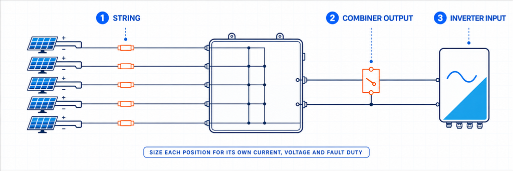
Mapa de protección DC solar PV mostrando posiciones de interruptores en string, salida de combinador y entrada de inversorUn generador solar es una cadena de circuitos eléctricamente diferentes. Marca el interruptor propuesto antes de abrir un catálogo:
String PV → entrada del combinador de string → salida DC combinada → entrada DC del inversor
Moverse una posición hacia la derecha cambia la trayectoria de la corriente. Los módulos en serie elevan la tensión. Los strings compatibles en paralelo elevan la corriente. Un interruptor en una entrada individual normalmente transporta un string; un interruptor en la salida común transporta todos los strings conectados a esa salida.
| Posición | Corriente a través del dispositivo | Función principal a establecer | Preselección habitual |
|---|---|---|---|
| String individual | Un string | Protección contra corriente inversa y aislamiento del string | fusible gPV o MCB DC con clasificación PV donde el diseño lo permita |
| Salida del combinador | Suma de los strings en paralelo | Protección del alimentador combinado y del cable de salida | MCB DC con clasificación PV, MCCB DC o interruptor-seccionador con protección separada |
| Entrada DC del inversor | Corriente asignada a esa entrada del inversor o trayectoria MPPT | Aislamiento del equipo y protección coordinada | Interruptor o seccionador especificado por el diseño del sistema |
La tabla dice deliberadamente “lista corta”. No se requiere automáticamente un interruptor en cada posición. Una string puede usar fusibles gPV; un inversor puede incluir ya un aislador DC adecuado; una salida puede necesitar aislamiento mientras la protección contra sobrecorriente se provee en otro lugar. Defina la función faltante antes de elegir el dispositivo.
El artículo sobre dimensionamiento de cajas combinadoras solares explica cómo la agrupación MPPT determina qué strings pueden compartir una salida. Completa primero esa decisión de arquitectura. Un interruptor no puede corregir strings que nunca debieron haberse puesto en paralelo.
Establece la ventana de corriente, no solo un amperaje mínimo
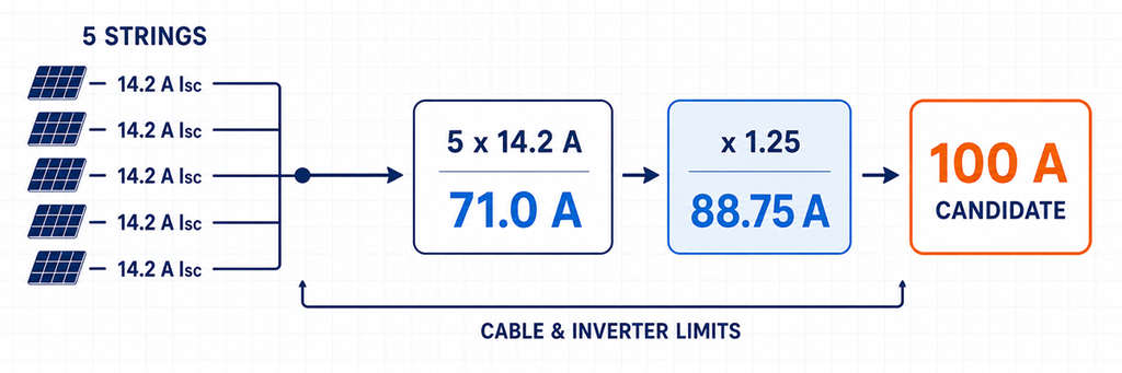
Dimensionamiento de corriente de interruptores DC solares desde cinco strings en paralelo hasta un candidato de 100 amperiosEl cálculo de corriente tiene dos lados. El interruptor debe soportar la corriente de diseño en las condiciones instaladas, pero no debe ser tan grande que el cable protegido o el equipo conectado quede fuera de sus límites.
Para strings PV emparejadas:
Isc,path = Np × Isc,módulo
donde:
- Isc,path es la base de corriente de cortocircuito para la trayectoria seleccionada en amperios;
- Np es el número de strings conectados en paralelo en esa trayectoria;
- Isc,módulo es la corriente de cortocircuito del módulo en su condición de prueba indicada.
El método de instalación del proyecto determina entonces el tratamiento de la corriente de diseño:
Idiseño = Isc,path × Kproyecto
Kproyecto no es un número para adivinar. Representa el factor actual requerido por las reglas de instalación adoptadas y la base de diseño. Los ejemplos norteamericanos comúnmente muestran 1.25 o 1.56 dependiendo de la clasificación del equipo y la ruta de cálculo. Los proyectos orientados a IEC deben usar los requisitos de instalación aplicables, los datos del módulo y las instrucciones del fabricante en lugar de etiquetar una de esas cifras como un “multiplicador IEC” universal.”
La ventana de selección útil es:
Corriente de carga requerida ≤ clasificación o ajuste utilizable del interruptor ≤ límite permitido del circuito protegido
El límite superior puede estar determinado por la ampacidad del cable reducida, la clasificación del terminal, el límite de entrada del inversor u otro componente protegido. Seleccionar el siguiente interruptor estándar por encima de Idiseño solo es válido cuando el límite superior aún pasa.
Los módulos en serie no multiplican la corriente del interruptor
Veinte módulos en serie no producen veinte veces la corriente del módulo. Aumentan el voltaje de la cadena mientras que la corriente de la cadena se mantiene basada en un solo módulo. Cinco cadenas idénticas en paralelo producen aproximadamente cinco veces la corriente. Por eso, dividir los vatios del arreglo por un voltaje DC supuesto es un sustituto pobre para la hoja de datos del módulo y el programa de cadenas.
Usa Isc e Imp para diferentes verificaciones
Isc es el punto de partida de la corriente de cortocircuito utilizado en el diseño de sobrecorriente PV. Imp describe la corriente de operación cerca de la potencia máxima y ayuda a verificar la carga MPPT del inversor y la operación normal. Mantenga ambos valores en la hoja de trabajo. No reemplace la base de protección con la Imp, más baja, y no olvide el límite de corriente de operación del inversor después de calcular desde Isc.
Mantenga los ejemplos IEC y norteamericanos en sus propios carriles
La guía de aplicación PV de Eaton para Norteamérica, por ejemplo, distingue entre interruptores moldeados con clasificación del 80 % y del 100 %. Su método trabajado usa 1,56 × Isc para un interruptor con clasificación 80% y 1.25 × Isc para un interruptor con clasificación del 100 %, junto con verificaciones de conductor y temperatura. Esas cifras son útiles dentro de ese contexto NEC/UL y de producto. No deben separarse de él ni publicarse como una regla global para PV.
Para un proyecto IEC, comience con la edición adoptada por el contrato o la jurisdicción. El alcance público de IEC 60364-7-712 confirma que aborda instalaciones eléctricas PV, pero una página de alcance no establece el cálculo completo para un proyecto específico. Registre la regla de diseño real junto a Kproyecto; esto mantiene la revisión aritmética y evita que un proveedor cambie silenciosamente los métodos.
Establezca la clasificación de voltaje desde Voc en frío y el diagrama de polos
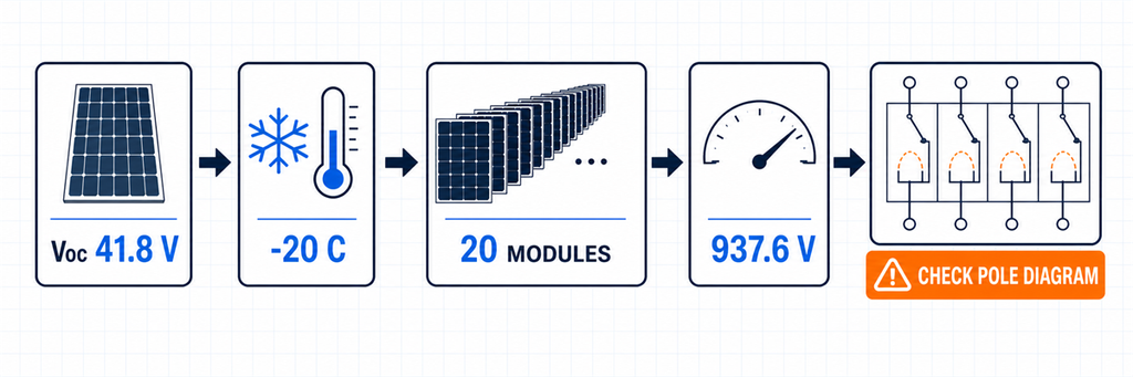
Cálculo de voltaje de cadena PV en clima frío y verificación de configuración de polos del interruptor DCEl voltaje de la cadena es más alto cuando los módulos están en circuito abierto y fríos. Un interruptor seleccionado solo con el Voc STC del módulo puede ser subclasificado en una mañana fría.
Donde el módulo proporciona un coeficiente de temperatura negativo de Voc en porcentaje por grado Celsius, un cálculo preliminar es:
Voc,frío,módulo = Voc,STC × [1 + |βVoc| × (25 − Tmín)]
Voc,frío,cadena = Ns × Voc,frío,módulo
donde Ns es el número de módulos en serie y Tmín es la temperatura mínima de diseño del proyecto. Ingrese −0,27 %/°C como 0,0027. Si el fabricante del módulo o el método de diseño adoptado especifica otro cálculo de temperatura, úselo de manera consistente en el inversor y en cada componente DC.
El voltaje DC declarado del interruptor debe ser al menos el voltaje máximo aprobado del circuito. También debe alcanzar esa clasificación en la disposición exacta de polos mostrada por su fabricante. Algunos interruptores DC de alto voltaje colocan varios contactos en serie para compartir la interrupción del arco. Un cuerpo de cuatro polos no equivale automáticamente a un interruptor de 1000 V o 1500 V.
Antes de ordenar, confirme:
- voltaje operativo nominal DC para el modelo exacto;
- número de polos utilizados en serie a ese voltaje;
- ruta de conductor positivo y negativo permitida;
- sensibilidad de polaridad y dirección de línea/carga;
- idoneidad declarada para aislamiento donde se requiera esa función.
La calculadora de voltaje de cadena en frío JUTRION existente puede proporcionar un resultado preliminar de Voc,frío,cadena resultado. Fue creado para el cribado de voltaje SPD PV, pero el voltaje frío de la cadena también es una entrada para verificaciones de interruptor, aislador, cable e inversor.
Use la ruta de falla para decidir si un interruptor puede proteger el circuito
La corriente nominal de un interruptor y su capacidad de ruptura responden preguntas diferentes:
- Corriente nominal o ajuste de disparo: ¿puede el dispositivo transportar corriente normal y proteger el circuito contra sobrecorriente aplicable?
- Capacidad de ruptura DC: ¿puede interrumpir de manera segura la corriente de falta prospectiva en la tensión DC indicada y la condición de cableado?
No compare una clasificación de 100 A de un interruptor con una contribución de corriente inversa de 50 A y concluya que el dispositivo puede interrumpir la falta. Una etiqueta de corriente normal no prueba la respuesta de disparo, la protección del conductor ni el rendimiento de interrupción en DC.
En una falta de string, los strings paralelos sanos pueden alimentar corriente inversa al string dañado. Una evaluación inicial es:
Iinversa,evaluación = (Np − 1) × Isc,cadena
Esto muestra por qué la exposición a corriente inversa crece a medida que se conectan más strings en paralelo. Por sí solo no selecciona un interruptor o fusible. El diseño final debe considerar la clasificación máxima de fusible en serie del módulo, la capacidad del conductor, la característica del dispositivo de protección y los requisitos de las reglas de instalación adoptadas.
En una salida combinada, identifique cada fuente que pueda alimentar la falla. Los módulos PV están limitados en corriente comparados con una red o batería, pero subarreglos en paralelo, equipos de conversión de potencia conectados y cualquier interfaz de almacenamiento pueden cambiar la corriente disponible. Si las baterías están conectadas a nivel DC, deje de tratar el circuito como un ejemplo solo PV; la evaluación de corriente de falla de baterías merece su propio diseño.
No Asuma que un Gran Número de Interrupción Resuelve una Mala Decisión de Disparo
Un interruptor puede tener una capacidad de interrupción última amplia y aun así no proteger el conductor previsto porque su umbral de disparo o su curva tiempo-corriente no es adecuada. Por el contrario, un interruptor de baja corriente puede tener una clasificación normal cercana a la carga pero carecer de la capacidad de interrupción DC requerida a la tensión real. Verifique tanto la clasificación de interrupción como la característica de protección.
Las fallas PV también pueden ocurrir cerca del extremo inferior del rango operativo de un interruptor. La selectividad entre dispositivos de cadena y un interruptor de salida no está garantizada simplemente porque el dispositivo de salida tenga la etiqueta de amperios mayor. Use datos de coordinación del fabricante donde la operación selectiva importe, y trate la curva de disparo reclamada como evidencia específica del modelo en lugar de una regla genérica de “curva C para solar”.
IEC 60947-2:2024 se aplica a interruptores automáticos para personas instruidas o calificadas con tensiones nominales de hasta 1000 V AC o 1500 V DC. Ese alcance de norma de producto respalda la regla clave de compra: obtener clasificaciones DC verificadas para el interruptor exacto, no una cifra de interrupción AC ni una etiqueta de marketing a nivel de familia.
Elija el DC MCB o DC MCCB Después de que el Deber Sea Visible
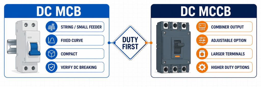
Comparación de DC MCB versus DC MCCB para protección de string solar y salida de combinador“Use un MCB por debajo de 63 A y un MCCB por encima de 63 A” es conveniente, pero no es un límite de ingeniería universal. Las gamas de productos se superponen. Algunas familias de DC MCB se extienden por encima de 63 A; algunos proyectos eligen un MCCB a una corriente más baja porque necesitan una capacidad de interrupción diferente, protección ajustable, terminales más grandes o accesorios.
| Necesidad del proyecto | DC MCB es la mejor opción cuando… | DC MCCB es la mejor opción cuando… |
|---|---|---|
| Formato de instalación | Un dispositivo compacto para riel DIN se ajusta al string o alimentador pequeño | Un dispositivo de panel en caja moldeada, conductores más grandes o barras colectivas están involucrados |
| Ajuste de protección | La característica fija declarada se adapta al circuito | Una unidad de disparo ajustable disponible ayuda a coordinar el alimentador |
| Deber de interrupción | La capacidad de interrupción DC verificada del modelo supera el nivel de falta | El circuito requiere un deber de interrupción DC verificado más alto |
| Control e indicación | La posición básica de la manija o las opciones auxiliares modulares son suficientes | Disparo por shunt, contactos auxiliares u operación remota son requeridos y soportados |
| Posición típica en PV | String individual o ramal de corriente más baja | Salida de combinador o alimentador de array de corriente más alta |
La decisión no se trata de qué familia es “mejor”. Se trata de qué producto verificado satisface la ventana de corriente, la disposición de tensión/polos, el deber de interrupción, la interfaz de cable y los requisitos de control de la ubicación. Después de que esos valores se conozcan, compare las Configuraciones de DC MCB JUTRION y los Configuraciones de DC MCCB JUTRION.
Decida si la Ubicación Necesita un Fusible, Interruptor o Aislador
Tres dispositivos a menudo aparecen en la misma caja combinadora, pero sus funciones no son intercambiables.
- Fusible gPV y portafusible: proporciona protección contra sobrecorriente para cadena o arreglo PV dentro de su función verificada. No proporciona aislamiento para mantenimiento a menos que el conjunto completo de fusible-interruptor esté diseñado para esa función.
- Interruptor automático DC: proporciona operación automática de sobrecorriente más conmutación dentro de sus clasificaciones declaradas. No satisface automáticamente una función de aislamiento requerida a menos que esté declarado adecuado para aislamiento.
- Seccionador DC: proporciona conmutación manual de carga y aislamiento dentro de su clasificación de utilización. No proporciona protección automática de sobrecarga o cortocircuito.
A nivel de string, los fusibles gPV son comunes porque los strings paralelos pueden alimentar corriente inversa a un string con falta y el módulo proporciona una clasificación máxima de fusible en serie. Un interruptor rearmable puede ser útil donde su deber PV y característica estén verificados, pero “rearmable” no es evidencia de que coordine mejor.
En una salida de combinador, un interruptor puede proteger el cable combinado y proporcionar conmutación. Otro diseño puede usar un seccionador porque la protección de sobrecorriente está ubicada en otro lugar. Indique qué función realiza el dispositivo; de lo contrario, dos proveedores pueden cotizar arquitecturas diferentes bajo la misma solicitud de “interruptor DC”.
Coordine el Interruptor con la Ruta DC Completa
Un interruptor correcto puede ser incorrecto en un sistema mal coordinado. Complete cinco verificaciones antes de fijar el modelo.
Cable
Verifique la ampacidad del conductor después de las correcciones por temperatura ambiente, agrupamiento, instalación y terminaciones. La clasificación o ajuste del interruptor debe permanecer dentro de la relación de protección permitida. No aumente el interruptor solo para detener disparos molestos sin revisar la temperatura del gabinete y el cable.
Inversor
Compare la tensión de string en frío con la tensión máxima de entrada DC. Compare la corriente de operación del string en paralelo con el límite de corriente MPPT/entrada, y la I totalsc con la corriente de cortocircuito permitida del inversor. El interruptor automático no autoriza una matriz que exceda los datos del inversor.
Fusibles de string
Confirme si cada string necesita protección contra corriente inversa y si el fusible/enlace seleccionado permanece por debajo de la clasificación máxima de fusible de serie del módulo mientras transporta la corriente requerida en las condiciones del gabinete. El interruptor automático de salida común y los fusibles de string normalmente protegen conductores diferentes.
SPD DC para PV
Un SPD limita la sobretensión transitoria; no es el dispositivo de sobrecorriente normal. Siga las instrucciones de protección de respaldo del fabricante del SPD y verifique su comportamiento de cortocircuito. La guía para selección de un SPD DC para solar PV cubre UCPV, Tipo 2/Tipo 1+2 y decisiones de nivel de protección.
Gabinete y ensamblaje
Las cajas combinadoras para exteriores pueden funcionar sustancialmente más calientes que el aire circundante. Utilice los datos reales de temperatura/altitud del interruptor automático, los límites de los terminales y las instrucciones de montaje. Los dispositivos de protección muy próximos entre sí, el calentamiento solar, las pérdidas en cables y el flujo de aire restringido afectan la corriente utilizable. Revise el ensamblaje completo de la caja combinadora PV, no solo la placa de características del interruptor automático.
Si una curva de catálogo muestra que el interruptor automático transporta menos corriente a la temperatura interna esperada, aplique esa curva antes de elegir el marco. Si no hay disponible una curva aplicable o datos de ensamblaje, aumentar la clasificación del interruptor automático mediante un porcentaje improvisado no es un diseño térmico defendible. El interruptor automático más grande también puede requerir un conductor, terminal o gabinete más grandes y puede que ya no proteja el cable original.
IEC 62548-1:2023 cubre los requisitos de diseño de arreglo PV incluyendo cableado DC, dispositivos de protección eléctrica, disposiciones de conmutación y puesta a tierra. IEC 60364-7-712:2025 se aplica a las instalaciones eléctricas de sistemas PV. Estos contextos de instalación son distintos de la norma de producto del interruptor automático.
Una matriz, tres decisiones diferentes de interruptor automático
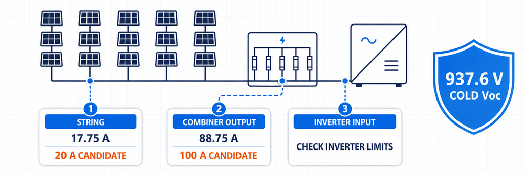
Ejemplo de dimensionamiento de interruptor DC solar comparando decisiones de cadena, salida del combinador y entrada del inversorDiseño ilustrativo: cada string tiene 20 módulos idénticos. Los datos del módulo indican Voc,STC = 41,8 V, Isc = 14,2 A y βVoc = −0,27%/°C. La temperatura mínima de diseño es −20°C. Cinco strings compatibles alimentan una entrada de inversor a través de una combinadora. Solo para este ejemplo, el método de corriente preliminar del proyecto utiliza 1,25 × Isc.
Primero, establezca el deber de tensión común
V del módulo en fríooc = 41,8 × [1 + 0.0027 × (25 − (−20))] = 46,88 V
V del string en fríooc = 20 × 46,88 = 937,6 V
Las cadenas están en paralelo en el combinador, por lo que sus voltajes no se suman. El dispositivo de cadena y el dispositivo de salida requieren ambos una disposición verificada de voltaje/polo por encima del voltaje máximo aprobado del circuito. Una clase DC de 1000 V es la lista inicial, sujeta al tratamiento adicional de voltaje del proyecto y al diagrama exacto del interruptor.
Posición 1: un string
Corriente preliminar de diseño de cadena = 14,2 × 1,25 = 17,75 A
Un dispositivo protector PV clasificado para 20 A es el primer candidato de corriente. Antes de elegir un MCB DC, compare este resultado con la clasificación máxima de fusible en serie del módulo, la capacidad de corriente del conductor, la protección requerida contra corriente inversa y la característica exacta de disparo. Un fusible gPV puede seguir siendo la mejor opción para protección de cadena.
Con cinco strings en paralelo, los cuatro strings sanos producen una pantalla inicial de corriente inversa de:
(5 − 1) × 14,2 = 56,8 A
Esa cifra explica por qué la protección de cadena merece atención. No significa que se deba instalar un interruptor de cadena de 56,8 A.
Posición 2: salida de combinadora
I totalsc = 5 × 14,2 = 71,0 A
Corriente preliminar de diseño de salida = 71,0 × 1,25 = 88,75 A
Un interruptor DC clase 100 A es una candidatura de corriente para la salida combinada. El paso de MCB a MCCB ahora depende del rango de producto disponible, capacidad de ruptura DC verificada, ajustes requeridos, tamaño de terminal y temperatura del recinto, no de una regla universal de 63 A.
Posición 3: entrada del inversor
La aritmética de corriente puede ser idéntica a la salida del combinador porque es el mismo alimentador. La decisión no es automáticamente idéntica. Confirme si el inversor ya proporciona un interruptor DC, si se requiere un interruptor externo, la corriente máxima de entrada y Isc, la disposición de conmutación permitida y la ubicación necesaria para un mantenimiento seguro.
| Posición | Punto de partida de corriente calculada | Dirección inicial del dispositivo | Decisión que permanece |
|---|---|---|---|
| Un string | 17,75 A | Candidato de dispositivo de protección PV de 20 A | fusible gPV o MCB DC; coordinación módulo/cable |
| Salida del combinador | 88,75 A | Candidato a interruptor DC clase 100 A | MCB/MCCB, capacidad de corte DC, ajustes y temperatura |
| Entrada del inversor | Corriente del mismo alimentador | Interruptor automático o interruptor-seccionador según se requiera | Límites del inversor y si ya existe protección |
El cálculo ha producido tres decisiones funcionales diferentes a partir de un solo arreglo. Eso es más útil que citar un solo tamaño de interruptor para “un sistema solar de 100 kW”.”
Leer la hoja de datos del interruptor como un conjunto de valores nominales conectados
No apruebe el dispositivo marcando un solo número. Lea estos valores nominales en conjunto:
- Ue: tensión nominal de servicio para la configuración de polos DC indicada;
- In o marco/ajuste: corriente nominal y ajuste disponible en condiciones de referencia;
- Capacidad de ruptura DC: rendimiento declarado de interrupción a la tensión DC correspondiente;
- característica de disparo: cómo y cuándo opera el dispositivo, no simplemente una letra B/C/D tomada de otra familia;
- declaración de aislamiento: si puede cumplir la función de aislamiento requerida;
- diagrama de polos y polaridad: la única conexión válida para el valor nominal de alta tensión declarado;
- datos de temperatura y altitud: la base para la corriente utilizable en el gabinete real;
- terminales: rango de conductores, material, preparación y par de apriete;
- accesorios: contactos auxiliares, disparo por derivación o operación remota donde el sistema los necesite.
Una etiqueta como “4P, 1000 V DC, 100 A” no revela el conjunto completo de potencia nominal conectada. Solicite la hoja técnica exacta y el diagrama de conexión del modelo pedido.
Tres señales de advertencia en la hoja de datos
- Un número de capacidad de corte sin tensión DC: el rendimiento de interrupción debe referirse a una tensión declarada y a una disposición de prueba.
- Una afirmación de 1000 V sin diagrama de polos: el comprador no puede confirmar cómo las cámaras de arco comparten la tensión ni dónde se conectan los conductores.
- Un valor de corriente nominal sin temperatura de referencia: el régimen del gabinete en la azotea permanece desconocido.
Estas omisiones no prueban automáticamente que un producto sea inadecuado, pero impiden una selección técnica. Resuélvalas antes de instalar el dispositivo en una cadena PV activa.
Preguntas Frecuentes
¿Qué tamaño de interruptor DC necesito para paneles solares?
Use el módulo Isc y el número de cadenas en paralelo en la ruta protegida, luego aplique el método de corriente requerido por el proyecto. Seleccione el siguiente valor nominal adecuado solo si también protege el cable con corriente reducida y se mantiene dentro de los límites del inversor y de los terminales. Verifique V en fríooc, capacidad de corte DC y cableado de polos por separado.
¿Puedo usar un interruptor AC en el lado DC solar?
Solo cuando el fabricante declare explícitamente el dispositivo exacto, la tensión DC, la capacidad de corte y la configuración de polos para esa aplicación DC. Una clasificación AC por sí sola es insuficiente porque un arco DC sostenido es más difícil de interrumpir.
¿Debe una cadena PV usar un fusible o un interruptor automático?
Los fusibles gPV son comunes para la protección contra corriente inversa en cadenas individuales. Se puede seleccionar un interruptor DC con clasificación PV cuando su característica, tensión, capacidad de corte y coordinación con cable/módulo sean adecuadas. La respuesta depende del diseño de protección, no de una preferencia por dispositivos reiniciables.
¿Cuándo debo elegir un MCCB DC en lugar de un MCB DC?
¿MCB DC?
Elija según el deber. Un MCCB se convierte en el candidato más robusto cuando la salida requiere un marco más grande, mayor capacidad de corte verificada, protección ajustable, terminales más grandes o accesorios de control. No se base en un límite universal de 63 A.
¿Necesito un interruptor de 2 polos o 4 polos para una cadena PV de 1000 V?
El fabricante del interruptor decide esto mediante el diagrama verificado de polos DC del modelo. Algunos productos requieren múltiples polos en serie para alcanzar 1000 V; otros usan una construcción diferente. Siga el diagrama exacto y las marcas de polaridad en lugar de elegir solo por el número de polos.
Complete la selección en cada posición
Para una cadena individual, resuelva la protección contra corriente inversa y el límite de protección en serie del módulo. En la salida del combinador, resuelva la corriente combinada, la protección del cable y la capacidad de corte DC. En la entrada del inversor, resuelva los límites del equipo y el punto de aislamiento requerido.
Solo entonces elija la familia de productos. Un compacto MCB DC puede ajustarse a la cadena o a un alimentador más pequeño; un MCCB DC puede ajustarse mejor a la salida combinada. El modelo final es aquel cuyos valores nominales de corriente, tensión, interrupción, polos y condiciones instaladas se refieren todos al mismo circuito—no cinco números individualmente impresionantes recogidos de condiciones diferentes.
