

Quelle taille de contacteur AC dois-je choisir ? Conversion kW en A pour moteurs, classifications AC-1 à AC-4 et sélection de bobine.
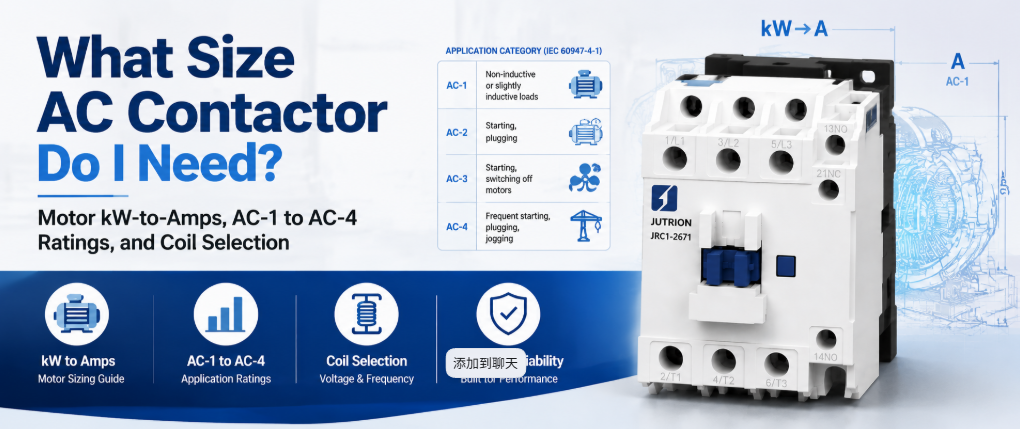
Réponse rapide : Que fait un contacteur AC ?
Un contacteur AC est un interrupteur commandé électriquement qui utilise un électroaimant actionné par bobine pour fermer et ouvrir un circuit de puissance sur commande, et il est conçu pour effectuer cela des milliers à des millions de fois sans que les contacts ne se soudent ou ne s’usent. Il commute le courant de charge lorsqu’on le lui demande. Il ne protège pas le circuit. Le dimensionner correctement signifie le dimensionner en fonction de la charge réelle, et non du chiffre le plus élevé indiqué sur l’étiquette.
Un contacteur marqué 20 A n'est pas un appareil de 20 A pour un moteur. La même unité physique peut être calibrée à 20 A pour un radiateur résistif et à 9 A pour un moteur à cage d'écureuil, car le courant d'appel du moteur et la coupure inductive sollicitent les contacts bien plus durement qu'un radiateur. Cette seule distinction provoque plus de défaillances précoces de contacteurs que toute autre erreur de sélection.
Ce guide couvre ce que le contacteur doit supporter, comment le calculer, quelle catégorie d'emploi s'applique, ainsi que les vérifications des pôles, de la bobine, des auxiliaires, de la durée de vie et de la coordination qui suivent le chiffre en ampères.
Faire correspondre la tâche de commutation au bon appareil
Avant de dimensionner quoi que ce soit, confirmez qu'un contacteur est le bon appareil pour la tâche. Les conceptions de panneaux échouent souvent parce qu'on attend d'un seul composant qu'il remplisse deux fonctions sans rapport entre elles.
| Appareil | Tâche principale | Fréquence de commutation | Déclenchement sur défaut |
|---|---|---|---|
| Contacteur AC | Établit et coupe le courant de charge sur commande | Conçu pour des cycles fréquents | Non. Nécessite un relais de surcharge ou un disjoncteur séparé |
| Relais universel | Commutation de faible puissance et contrôle de signaux | Calibré pour un service plus léger | Non |
| MCB ou MCCB | Protection contre les surintensités et les courts-circuits | Fonctionnement occasionnel, pas de cycles de routine | Oui |
| Démarreur de moteur | Contacteur et relais de surcharge en un seul ensemble | Identique au contacteur | Oui, via le relais de surcharge |
| Démarreur progressif ou VFD | Rampe contrôlée du courant du moteur | Contrôle continu plutôt que marche/arrêt | Varie selon le modèle |
Si la question est de savoir comment commuter une charge en marche et en arrêt de manière répétée sur commande, la réponse est un contacteur. Si la question est de savoir ce qui protège le circuit contre la surcharge, c'est un autre appareil. Traiter le contacteur comme s'il faisait les deux est l'une des erreurs de conception de panneau les plus courantes.
Pourquoi un relais ou un disjoncteur ne peut pas le remplacer
Un relais universel peut fermer un circuit, mais il n'est pas conçu pour le faire à des niveaux de courant de moteur ou de radiateur sur le long terme. Les contacteurs sont calibrés pour une durée de vie mécanique de plusieurs millions de manœuvres, tandis que les relais universels sont calibrés pour une petite fraction de cela sous une charge électrique réelle. La différence réside dans le matériau des contacts, la force du ressort et la suppression de l'arc. Les contacteurs utilisent la géométrie des contacts et, sur les châssis plus grands, les chambres de coupure nécessaires pour couper le courant inductif du moteur de manière répétée sans que les contacts ne se piquent ou ne se soudent. Un relais poussé dans ce service échoue généralement en se soudant fermé sous charge, ce qui est un mode de défaillance bien pire que l'usure progressive d'un contacteur.
Un disjoncteur est conçu pour protéger un circuit et être actionné occasionnellement, pas pour être cyclé dans le cadre d’une logique d’automatisation normale. Utiliser un disjoncteur comme interrupteur de service raccourcit sa durée de vie protectrice et n’est pas conforme à sa classification. Le contacteur et le dispositif de protection ont deux fonctions différentes et doivent coexister dans le même circuit.
Fonctionnement d'un contacteur AC
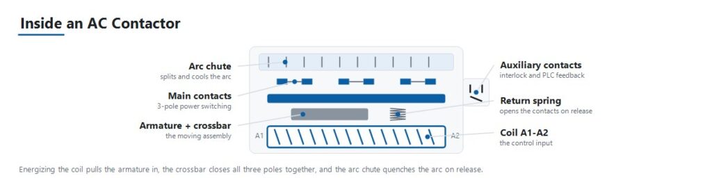
La séquence de fonctionnement explique la plupart des modes de défaillance abordés plus loin dans ce guide.
- Le signal de commande excite la bobine. Un circuit de commande, tel qu'une sortie d'automate, un thermostat ou une logique à boutons-poussoirs, applique une tension à la bobine à sa tension nominale.
- L'électroaimant attire l'armature. La bobine excitée crée un champ magnétique qui attire une armature mobile vers un noyau fixe.
- Les contacts principaux se ferment. Le mouvement de l'armature ferme les contacts de puissance principaux par l'intermédiaire d'une traverse commune, reliant la charge à l'alimentation.
- Les contacts auxiliaires changent d'état. De petits contacts auxiliaires liés à la même armature s'ouvrent ou se ferment en même temps que les contacts principaux. Ils assurent le verrouillage, la signalisation et la confirmation à un automate que le contacteur s'est effectivement fermé.
- La force du ressort maintient la pression de contact. Une pression de contact stable sous vibrations et en charge est ce qui empêche le rebond des contacts et l'échauffement résistif au niveau de la face de contact.
- La désexcitation de la bobine ouvre le circuit. Lorsque le signal de commande disparaît, le champ magnétique s'effondre et un ressort de rappel ramène l'armature en arrière, ouvrant les contacts principaux.
- La suppression de l'arc gère l'interruption. Ouvrir un circuit en charge, surtout une charge de moteur inductive, produit un arc entre les contacts qui se séparent. La géométrie des contacts et les chambres de coupure éteignent cet arc assez rapidement pour éviter tout dommage à chaque cycle.
Les catégories d'emploi déterminent le courant assigné réel
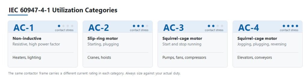
La norme IEC 60947-4-1 définit des catégories d'emploi qui décrivent la sévérité d'une charge pour les contacts, et non simplement le nombre d'ampères qu'elle consomme. C'est l'étape à laquelle remontent la plupart des erreurs de sélection.
| Catégorie | Type de charge | Service de commutation | Application typique |
|---|---|---|---|
| AC-1 | Non inductif ou légèrement inductif, facteur de puissance élevé | Pas d'appel de courant significatif | Résistances de chauffage, batteries de chauffage CVC, éclairage général |
| AC-2 | Moteurs à bagues (rotor bobiné) | Démarrage et freinage par contre-courant en charge | Grues, palans |
| AC-3 | Moteurs à cage d'écureuil | Démarrage et coupure d'un moteur en marche | Pompes, ventilateurs, compresseurs |
| AC-4 | Moteurs à cage d'écureuil | Marche par à-coups, freinage par contre-courant, inversion rapide | Ascenseurs, convoyeurs, machines-outils |
La conséquence est qu'un seul contacteur possède plusieurs courants assignés différents. Un JUTRION JRC1-D09 est assigné à 20 A en catégorie AC-1 et à 9 A en catégorie AC-3. Les deux chiffres décrivent le même appareil physique. Dimensionner une pompe sur la base des 20 A place le contacteur à plus du double de son courant assigné en service moteur, et les contacts le montreront.
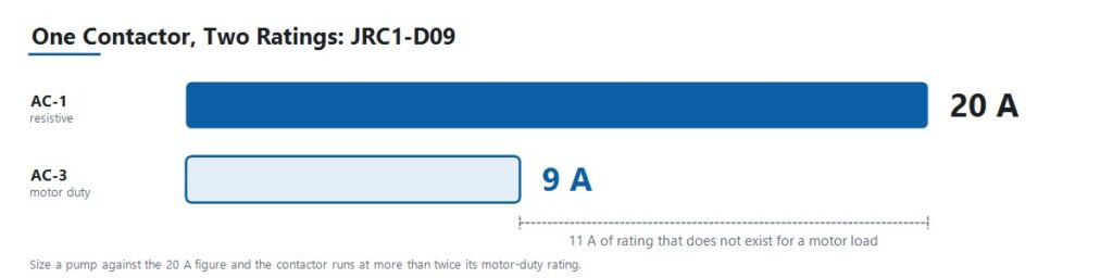
Lisez chaque courant assigné publié avec la catégorie à laquelle il appartient. Une taille de contacteur n'est pas un modèle pour grue ni un modèle pour marche par à-coups. C'est une seule taille avec plusieurs courants assignés, et le service détermine quel courant assigné s'applique au projet.
Convertir les données du moteur en ampères
Utilisez directement un courant à pleine charge vérifié lorsque le projet en fournit déjà un. Lorsque les données sont données en puissance moteur, convertissez-les en utilisant la tension et le montage de phases corrects.
Moteurs triphasés
I = P × 1 000 / (√3 × VLL × cos φ × η)
Charges monophasées
I = P × 1 000 / (V × cos φ × η)
Ici, I est le courant de ligne en ampères, P est la puissance assignée de sortie du moteur en kW, VLL est la tension triphasée entre phases, V est la tension monophasée, cos φ est le facteur de puissance, et η est le rendement.
Le facteur de puissance des moteurs asynchrones standard se situe généralement entre 0,80 et 0,88, et le rendement entre 0,85 et 0,93 selon la classe d'efficacité. Utilisez les valeurs de la plaque signalétique dès qu'elles sont disponibles. Les plages typiques sont destinées à un travail préliminaire avant réception de la fiche technique du moteur.
Pour les charges monophasées purement résistives telles que les éléments chauffants, le facteur de puissance et le rendement sont effectivement unitaires, et l'expression se réduit à I = P × 1 000 / V.
La Calculateur de dimensionnement de contacteur AC JUTRION effectue le même calcul et renvoie un courant opérationnel AC-3 minimal. C'est un point de départ pour la spécification, pas un substitut à la plaque signalétique du moteur ni aux tableaux de courants assignés du fabricant.
Appliquer les multiplicateurs selon le type de charge et le déclassement selon la température ambiante
Certaines charges consomment beaucoup plus que leur courant en régime établi au moment de la commutation. Une pratique industrielle de longue date applique un multiplicateur pour tenir compte de ce comportement. Ces conventions ne sont pas des valeurs définies dans la norme IEC 60947-4-1, alors traitez-les comme une première approximation et confirmez-les avec les données réelles d'appel de courant pour les circuits critiques ou de grande taille.
| Type de charge | Multiplicateur conventionnel | Raison |
|---|---|---|
| Batteries de condensateurs | Environ 1,5 × courant assigné du condensateur | L'appel de courant capacitif à la mise sous tension est sévère et très bref |
| Transformateurs et postes de soudage | Environ 2 × courant assigné | Le courant d'appel magnétisant peut atteindre plusieurs fois le courant en régime permanent |
| Éclairage à décharge gazeuse et HID | Environ 1,1 à 1,4 × courant nominal | Comportement d'appel et de préchauffage du ballast |
| Refroidissement insuffisant ou enceinte densément remplie | 110 à 120 pour cent du courant nominal de charge | Une température interne élevée réduit la capacité de courant |
| Moteur fonctionnant en continu, service de longue durée | Courant nominal du contacteur réduit d'environ 30 pour cent | Charge thermique continue des contacts |
Température ambiante et conditions de l'enceinte
Le courant nominal d'un contacteur suppose la température ambiante de référence indiquée sur sa fiche technique. Au-dessus de cette température, la capacité de transport de courant diminue, mais la pente de déclassement est spécifique au fabricant et au cadre. Utilisez la courbe de déclassement de la documentation réelle du produit plutôt qu'un pourcentage générique.
Deux conditions s'appliquent quel que soit le produit. Premièrement, basez le calcul sur la température à l'intérieur de l'enceinte, et non sur celle de la pièce. Un panneau densément rempli dans une usine chaude fonctionne à une température considérablement plus élevée que l'ambiance. Deuxièmement, les contacteurs montés côte à côte sans espacement se chauffent mutuellement, respectez donc l'espacement minimal du fabricant ou déclasssez davantage.
Un exemple concret : moteur de pompe de 4 kW à 400 V
Un moteur de pompe centrifuge triphasé dans une armoire OEM de traitement d'eau. Service standard de démarrage et arrêt, environ 20 démarrages par heure, température ambiante de l'armoire autour de 35 °C.
Étape 1. Établir la catégorie d'utilisation. Un moteur à induction à cage d'écureuil, démarré et arrêté normalement, est de catégorie AC-3. Il n'est pas AC-1, même si la charge est décrite comme une simple pompe.
Étape 2. Calculer le courant à pleine charge. Les valeurs de la plaque signalétique sont 4 kW, 400 V, cos φ = 0,85, η = 0,90.
I = 4 × 1 000 / (1,732 × 400 × 0,85 × 0,90)
En calculant le dénominateur : 1,732 × 400 = 692,8, puis × 0,85 = 588,9, puis × 0,90 = 530,0.
I = 4 000 / 530,0 ≈ 7,6 A
Étape 3. Sélectionner selon la classification AC-3. L'exigence est un contacteur dont la capacité AC-3 couvre 7,6 A avec marge. Le JRC1-D09 est noté 9 A en AC-3, offrant environ 18 % de marge par rapport au courant nominal calculé. Notez ce qui n'a pas été fait : le même JRC1-D09 supporte un courant AC-1 de 20 A, et dimensionner cette pompe sur cette valeur aurait été l'erreur de sélection de contacteur la plus courante.
Étape 4. Vérifier l'ambiance et le service. À une ambiance de panneau de 35 °C avec 18 pour cent de marge, vérifiez le chiffre par rapport à la courbe de déclassement du produit avant de vous engager. Cette marge est confortable dans un panneau bien ventilé et plus serrée dans un panneau densément rempli. À 20 démarrages par heure, confirmez que les opérations nominales par heure et la durée de vie électrique AC-3 dépassent confortablement le service attendu sur la durée de vie du panneau.
Étape 5. Spécifier la tension de bobine. Le secondaire du transformateur de commande du tableau est en 220 V AC, donc la bobine est spécifiée à 220 V. Ce n’est pas 400 V, même si le moteur fonctionne à 400 V.
Étape 6. Ajouter la protection. Associez le contacteur à un relais de surcharge correctement dimensionné et réglé au courant à pleine charge du moteur, et confirmez la coordination de Type 1 ou Type 2 avec le disjoncteur ou fusible en amont. Un démarrage normal en moins de 10 secondes indique une classe de déclenchement Classe 10 ici. Le calculateur de réglage du relais de surcharge convertit le courant de plaque signalétique, le facteur de service et la durée de démarrage en un réglage préliminaire et une classe de déclenchement.
Résultat : un JRC1-D09, tripolaire, avec une bobine 220 V AC, plus un relais thermique. La sélection a été dérivée de la charge, pas d'un catalogue.
La même procédure s'applique pour des puissances plus élevées. Un moteur de 18,5 kW sous 400 V correspond à environ 35 A en charge nominale et nécessite un contacteur avec un courant AC-3 supérieur à cette valeur.
Utilisez ce processus de sélection de contacteur AC en sept étapes
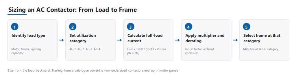
Étape 1 : Identifier le type de charge et la catégorie d'utilisation
Établissez si la charge est résistive, un moteur standard à cage d'écureuil, un moteur à rotor bobiné démarrant sous charge, ou un moteur sujet aux impulsions et inversions. Tout ce qui suit dépend de cette réponse, car elle détermine laquelle des plusieurs classifications de courant du contacteur s'applique réellement.
Étape 2 : Calculer le courant opérationnel et confirmer la tension
Utilisez les formules ci-dessus pour obtenir le courant à pleine charge, appliquez le multiplicateur de type de charge pertinent, puis confirmez que le courant opérationnel nominal du contacteur Ie à votre catégorie d'utilisation le couvre avec marge. Faites correspondre la tension opérationnelle nominale Ue à la tension de ligne du système.
Étape 3 : Sélectionner la tension de bobine
La tension de la bobine est une spécification distincte de la tension de charge. Un circuit moteur 380 V peut être commandé par une bobine 24 V DC ou 220 V AC selon l'architecture de commande. Confirmez ce que le circuit de commande fournit réellement, qu'il s'agisse d'une sortie PLC, d'un secondaire de transformateur de commande ou d'une alimentation de commande DC, avant de commander.
Étape 4 : Choisir le nombre de pôles et la configuration
Trois pôles est standard pour les charges de moteurs triphasés. Quatre pôles est utilisé lorsqu'une commutation du neutre ou un circuit indépendant supplémentaire est requis. Confirmez la disposition par rapport à la conception de mise à la terre du système, car la commutation du neutre est requise dans certains systèmes et inutile ou interdite dans d'autres.
Étape 5 : Spécifier les contacts auxiliaires
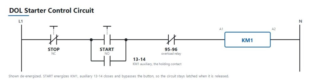
Déterminez combien de contacts auxiliaires normalement ouverts et normalement fermés sont nécessaires pour le verrouillage, le retour d'état PLC et les lampes indicatrices, et s'ils sont intégrés ou ajoutés comme bloc auxiliaire séparé. Dans un démarreur direct standard, un contact auxiliaire câblé en parallèle avec le bouton de démarrage est ce qui verrouille le circuit de commande pour que le contacteur reste alimenté après que l'opérateur relâche le bouton. Les contacts auxiliaires sont peu coûteux à spécifier au stade de la conception et difficiles à ajouter après coup.
Étape 6 : Vérifier la durée de vie électrique par rapport au cycle de service réel
Pour les applications à cycles fréquents telles que la marche par à-coups, l'inversion ou les séquences d'automatisation à haute fréquence, vérifiez les opérations nominales par heure et la durée de vie électrique dans votre catégorie d'utilisation. La durée de vie mécanique, mesurée sans charge, est toujours la valeur la plus élevée et la moins pertinente.
Étape 7 : Coordonner avec la protection en amont
Associez le contacteur à un relais thermique correctement dimensionné pour les charges moteur, puis coordonnez avec un disjoncteur ou un fusible en amont dimensionné pour la protection contre les courts-circuits. Sur les tableaux de distribution plus importants, ce dispositif en amont est souvent un disjoncteur à air. La sélection du contacteur est un maillon d'une chaîne qui va du courant de charge, au calibre du disjoncteur, au courant de défaut présumé, au pouvoir de coupure du dispositif. Bien choisir le contacteur tout en laissant cette chaîne non vérifiée ne fait que déplacer le problème.
Les normes IEC 60947-4-1 et NEMA ne sont pas des étiquettes interchangeables
Les contacteurs AC vendus à l'international sont généralement conformes à la norme IEC 60947-4-1, qui définit les catégories d'utilisation et la structure des caractéristiques utilisées dans ce guide. La cinquième édition actuelle a été publiée en 2023 et remplace celle de 2018. Il est utile de vérifier quelle édition une spécification de projet référence, car elles ne sont pas identiques.
Les marchés nord-américains font couramment référence aux calibrages de contacteurs NEMA ICS 2 au lieu des catégories d'utilisation IEC, ou parallèlement à celles-ci. Les deux systèmes classifient les contacteurs différemment, car la NEMA utilise des classes de taille plutôt que AC-1 à AC-4. Une spécification rédigée pour un marché ne se traduit pas automatiquement pour l'autre. Lors de l'approvisionnement pour un projet nord-américain, confirmez quel cadre la spécification de l'acheteur exige réellement avant de citer une pièce.
Traitez la norme de produit, le code d'installation et toute exigence spécifique au marché comme trois questions distinctes. Confirmer l'une ne répond pas aux autres.
Coordination de type 1 et de type 2
La coordination contre les courts-circuits selon la norme IEC 60947-4-1 détermine l'ampleur des dommages qu'un défaut cause au contacteur et au démarreur. Le type 1 permet des dommages à l'équipement après un défaut de court-circuit, à condition que les dommages soient contenus et qu'aucun danger n'en résulte, et l'équipement peut nécessiter une réparation ou un remplacement. Le type 2 exige que l'équipement reste apte à une utilisation ultérieure, seul un léger soudage des contacts étant permis. Ce sont des résultats commerciaux et techniques différents. Confirmez lequel la spécification du projet exige avant de sélectionner la combinaison.
Choisir entre les calibrages JUTRION JRC1
JUTRION fabrique la série de contacteurs AC JRC1 sur ses propres lignes de production à Wenzhou, Zhejiang, construits selon la norme IEC 60947-4-1. Les options de tension de bobine incluent 24 V, 48 V, 110 V, 220 V et 380 à 415 V à 50 ou 60 Hz. Chaque unité est testée pour le fonctionnement mécanique, la performance de la bobine et la commutation électrique avant expédition.
Voici les points de calibrage publiés pour les quatre catégories d'utilisation. Lisez le tableau par catégorie plutôt que par modèle, car le même cadre apparaît sous plus d'une catégorie avec un calibrage différent.
| Catégorie | Point de calibrage | Service que cela représente |
|---|---|---|
| AC-1 | JRC1-D09, 20 A | Résistances de chauffage, batteries de chauffage CVC, éclairage général |
| AC-2 | JRC1-D25, 25 A | Moteurs à rotor bobiné démarrant en charge, grues et palans |
| AC-3 | JRC1-D09, 9 A | Moteurs à cage d'écureuil, démarrage et arrêt normaux, pompes et ventilateurs |
| AC-4 | JRC1-D18, 7,7 A | Marche par à-coups, freinage par inversion, inversion rapide, ascenseurs et convoyeurs |
Le JRC1-D09 apparaît deux fois, à 20 A sous AC-1 et 9 A sous AC-3, car ce sont deux calibrages du même contacteur physique sous deux services différents. Pour un circuit moteur à induction standard, qui couvre la majorité des applications de pompes, ventilateurs et compresseurs, dimensionnez selon le calibrage AC-3 comme indiqué dans l'exemple de calcul. Pour un service de marche par à-coups ou d'inversion, dimensionnez plutôt selon AC-4, où le même cadre supporte un courant substantiellement inférieur.
Des calibrages de cadre supérieurs à ces points publiés sont disponibles. La sélection finale du modèle doit être basée sur les calibrages spécifiques au modèle et les conditions du projet, et non sur un chiffre de courant seul.
Appliquer la logique de sélection à cinq scénarios de tableau
Tableau moteur standard pour pompes, ventilateurs et compresseurs
Un fabricant OEM construisant des tableaux de commande pour équipements CVC ou de traitement de l'eau spécifie des contacteurs pour un service simple de démarrage et d'arrêt de moteur. C'est la catégorie AC-3. Dimensionnez le calibrage AC-3 par rapport au courant à pleine charge calculé, associez-le à un relais thermique correctement dimensionné et faites correspondre la tension de bobine à la sortie du transformateur de commande du tableau.
Tableau de grue ou de palan avec moteurs à rotor bobiné
Un fabricant OEM de grues nécessite des contacteurs qui gèrent le démarrage à couple élevé et le service de freinage par inversion sur des moteurs à rotor bobiné, ce qui est la catégorie AC-2. Ces charges sont plus éprouvantes pour les contacts que le service AC-3 standard en raison des démarrages répétés en charge et de l'inversion. Un sous-dimensionnement ici apparaît comme une usure prématurée des contacts plutôt qu'une défaillance immédiate, ce qui le rend facile à diagnostiquer à tort comme un problème de qualité.
Commande d'ascenseur ou de convoyeur avec marche par à-coups et inversion
Un constructeur de machines a besoin de contacteurs pour une application avec inversion fréquente de direction et mouvements d'avance par à-coups, ce qui est la catégorie AC-4, la plus exigeante des quatre. La durée de vie électrique au taux réel d'opérations par heure importe plus ici que dans tout autre scénario. Le sous-dimensionnement de cette catégorie est le moyen le plus rapide de consommer la durée de vie nominale d'un contacteur.
Commutation de banc de condensateurs pour la correction du facteur de puissance
Une installation ajoutant des condensateurs de correction du facteur de puissance nécessite des contacteurs dimensionnés par rapport à l'appel capacitif, conventionnellement environ 1,5 fois le courant nominal du condensateur, et souvent spécifiés avec des résistances de précharge ou comme contacteurs dédiés à la commutation de condensateurs. Le calibrage AC-1 standard n'est pas adéquat, car l'appel capacitif est un service de commutation distinct plutôt qu'une version atténuée d'un service résistif.
Tableau de chauffage résistif ou d'éclairage
Un constructeur de tableaux qui commute des batteries de chauffage CVC ou de grandes charges d'éclairage travaille en catégorie AC-1, la moins exigeante, puisqu'il n'y a pas d'appel de courant significatif ni de surtension inductive à gérer. L'éclairage à décharge et HID fait exception et nécessite le multiplicateur de 1,1 à 1,4 pour l'appel de courant du ballast. C'est également le cas où les acheteurs sur-spécifient parfois en choisissant un composant classé AC-3 là où un AC-1 suffirait, ce qui n'est pas dangereux, seulement un coût inutile.
Évitez les neuf erreurs qui causent une défaillance précoce du contacteur
| Erreur | Conséquence | Prévention |
|---|---|---|
| Dimensionnement selon la classification AC-1 pour une charge moteur | Contacteur sous-dimensionné pour son usage réel, les contacts se soudent ou s'usent prématurément | Toujours dimensionner selon la classification de la catégorie d'utilisation réelle |
| Omettre le relais de surcharge | Le moteur et le contacteur tous deux exposés à une surintensité prolongée | Associez chaque circuit moteur à un relais de surcharge correctement dimensionné |
| Ignorer la fréquence de commutation par rapport à la durée de vie électrique | Un contacteur correctement dimensionné en courant échoue quand même prématurément en service à cycles élevés | Vérifiez les opérations nominales par heure et la durée de vie électrique dans votre catégorie |
| Tension de bobine inadaptée | Le contacteur ne s'enclenche pas, ou la bobine grille | Confirmer par rapport à la tension réelle du circuit de commande, et non à la tension de charge |
| Aucune vérification de coordination en amont | Un défaut de court-circuit détruit le contacteur inutilement | Vérifier la coordination de type 1 ou de type 2 avant de finaliser la conception |
| Contacteurs inverseurs sans verrouillage | Les deux contacteurs peuvent se fermer simultanément, créant un court-circuit entre phases | Spécifier le verrouillage mécanique et électrique sur les paires d'inverseurs |
| Ignorer la température ambiante et le déclassement de l'enceinte | Durée de vie réduite malgré toutes les autres spécifications correctes | Déclasser en utilisant la courbe du produit et la température de l'enceinte |
| Oublier le multiplicateur du type de charge | L'appel de courant d'un condensateur, d'un transformateur ou d'un éclairage dégrade les contacts au fil du temps | Appliquer le multiplicateur conventionnel pour le type de charge |
| Spécifier les contacts auxiliaires trop tard | Retouche coûteuse du tableau ou blocs additifs peu pratiques | Déterminer les besoins de verrouillage et de retour d'information au stade de la conception |
Installer, mettre en service et diagnostiquer le contacteur
La plupart des défauts de contacteur signalés comme des défauts de produit sont des symptômes d'un problème de dimensionnement, de coordination ou d'alimentation de commande. Le tableau ci-dessous associe les symptômes courants aux vérifications qui identifient la cause.
| Symptôme | Causes possibles | Vérifications utiles |
|---|---|---|
| Vibre ou bourdonne fortement | Tension de bobine faible ou instable, spire de déphasage usée, noyau magnétique sale ou desserré | Mesurer la tension de bobine sous charge, inspecter la face du noyau, vérifier la stabilité de l'alimentation de commande |
| Contacts soudés fermés | Sous-dimensionné pour la catégorie réelle, événement de court-circuit sans coordination adéquate, fréquence de commutation excessive | Vérifier le dimensionnement par catégorie, examiner l'historique des défauts en amont, comparer les opérations par heure à la durée de vie électrique nominale |
| Pas de collage bien que le signal de commande soit présent | Bobine en circuit ouvert, mauvaise tension de bobine, blocage mécanique, fusible de commande grillé | Mesurer la résistance et la tension de la bobine aux bornes, vérifier le fusible de commande, inspecter la présence d'obstruction |
| Contacts piqués ou brûlés | Usure normale en fin de vie, sous-dimensionné pour la catégorie de service, mauvaise suppression d'arc à haute fréquence de commutation | Comparer l'état à la durée de vie électrique nominale, revérifier le dimensionnement par catégorie, inspecter la chambre de coupure |
| Le retour d'information auxiliaire ne correspond pas à l'état du contact principal | Bloc auxiliaire usé ou mal aligné, usure de la liaison mécanique | Tester la continuité auxiliaire indépendamment, inspecter la liaison à l'ensemble du contact principal |
| Bornes en surchauffe | Serrage desserré, conducteur sous-dimensionné, couple de serrage incorrect à l'installation | Vérifier le couple de serrage des bornes par rapport à la spécification, vérifier le dimensionnement du conducteur, image thermique sous charge |
| La bobine grille de façon répétée | Surtension prolongée sur le circuit de commande, température ambiante excessive, blocage mécanique empêchant le collage complet | Mesurer la tension de commande dans toutes les conditions de fonctionnement, vérifier le blocage, vérifier la température ambiante |
Des défaillances précoces répétées dans la même application indiquent presque toujours une inadéquation de dimensionnement, de coordination ou de cycle de service plutôt qu'un lot défectueux. Diagnostiquer la cause avant de recommander le même numéro de pièce.
Protéger la bobine et tout ce qui la commande
La désexcitation d'une bobine inductive produit un transitoire de tension. Lorsqu'une sortie transistor PLC, un petit relais intermédiaire ou un contrôleur électronique commande directement cette bobine, le transitoire se propage en retour. C'est une cause fréquente de défaillance des sorties PLC et de contacts piqués sur relais intermédiaires, et c'est facile à éviter. Utilisez un snubber RC sur les bobines AC, et une diode de roue libre ou un varistor sur les bobines DC. Notez le compromis : une diode de roue libre simple prolonge notablement le temps de coupure, ce qui importe lorsque le contacteur fait partie d'une fonction d'arrêt liée à la sécurité avec un temps de réponse spécifié.
Confirmer la tolérance de tension de fonctionnement de la bobine plutôt que de supposer que la valeur nominale tient. Une longue longueur de câble de commande ou un transformateur de commande sous-dimensionné peut mettre la tension réelle de la bobine en dessous de la plage dans laquelle la bobine collera et se maintiendra, et le symptôme apparaît comme un bourdonnement plutôt que comme un défaut de câblage évident.
Indiquer ces paramètres lors de la demande de devis
Une demande de contacteur qui inclut les informations suivantes peut recevoir une réponse avec un modèle spécifique dès la première réponse. Une demande qui ne donne qu'un chiffre d'ampérage nécessite normalement plusieurs tours de clarification, car une valeur de courant brute n'identifie pas le service auquel elle s'applique.
- Application ou équipement commandé
- Type de charge : moteur, chauffage, éclairage, condensateur ou transformateur
- Catégorie d'utilisation, si déjà déterminée
- Puissance nominale du moteur en kW, ou charge en kW
- Tension et fréquence du système
- Courant à pleine charge calculé
- Service : démarrages par heure, et si l'application inverse ou fonctionne par à-coups
- Tension de bobine requise, et AC ou DC
- Nombre de pôles, tripolaire ou tétrapolaire
- Contacts auxiliaires requis, normalement ouverts et normalement fermés
- Dispositif de protection en amont, disjoncteur ou fusible
- Température ambiante du panneau
- Mode de montage, rail DIN ou vis
- Quantité de commande et marché de destination
- Toute exigence OEM ou ODM
Questions fréquemment posées
Quelle est la différence entre un contacteur AC et un démarreur moteur ?
Un démarreur de moteur est un contacteur combiné à un relais de surcharge dans un seul ensemble, conditionné spécifiquement pour les circuits de moteur. Un contacteur autonome assure uniquement la fonction de commutation, et la protection contre les surcharges est ajoutée séparément.
Un contacteur peut-il être utilisé à la fois pour des charges AC-1 et AC-3 ?
Le même contacteur physique est généralement homologué pour plusieurs catégories, mais avec un courant assigné différent pour chacune. Dimensionnez selon l'intensité correspondant à la catégorie d'emploi de la charge réelle, et non selon le chiffre le plus élevé sur l'étiquette.
Comment calculer le courant pour le dimensionnement d'un contacteur ?
Pour un moteur triphasé, utilisez I = P × 1 000 / (√3 × VLL × cos φ × η), où P est la puissance assignée en kW, VLL est la tension entre phases, cos φ est le facteur de puissance, et η est le rendement. Appliquez ensuite tout multiplicateur de type de charge et confirmez le résultat par rapport à l'intensité assignée du contacteur dans votre catégorie d'emploi.
Un contacteur plus grand est-il toujours plus sûr ?
Non. Le surdimensionnement gaspille du coût et de l'espace dans le panneau, et sur certaines charges, les contacts d'un contacteur surdimensionné transportent trop peu de courant pour rester propres. Dimensionnez avec une marge raisonnable au-dessus du courant à pleine charge calculé dans la bonne catégorie plutôt que de sauter deux tailles de boîtier.
Quelle tension de bobine dois-je choisir ?
Adaptez-le à ce que le circuit de commande fournit réellement, qu'il s'agisse d'une sortie PLC, d'un secondaire de transformateur de commande ou d'une alimentation DC du tableau. Ce n'est pas la tension côté charge que le contacteur commute.
Pourquoi mon contacteur ronronne-t-il ou cliquette-t-il ?
Les causes habituelles sont une tension de bobine faible, instable ou incorrecte, ou une face de noyau magnétique usée ou sale sur une unité à bobine AC. Mesurez la tension de bobine en conditions de charge réelles et inspectez la face du noyau avant de conclure que l'unité est défectueuse.
Ai-je encore besoin d’un relais de surcharge si j’utilise un contacteur ?
Oui, pour les circuits moteurs. Un contacteur commute sur commande mais ne déclenche pas en cas de surintensité prolongée, ce qui est la fonction du relais de surcharge. Les deux dispositifs fonctionnent ensemble et ne se substituent pas l'un à l'autre.
Combien de cycles de commutation un contacteur peut-il supporter ?
Cela dépend de la taille du cadre et, plus important encore, de la catégorie d'utilisation et du niveau de courant auquel il fonctionne. La durée de vie mécanique mesurée sans charge est généralement bien supérieure à la durée de vie électrique sous charge, et la durée de vie électrique diminue davantage à des fréquences de commutation plus élevées. Vérifiez la durée de vie électrique nominale au cycle de service réel.
Deux contacteurs peuvent-ils être câblés en parallèle pour partager le courant ?
Ceci n'est généralement pas recommandé pour la commutation de charge principale. Les contacts ne se ferment jamais exactement au même instant, donc un seul dispositif supporte le courant d'appel complet. Utilisez plutôt un contacteur unique de taille appropriée.
Quelle est la différence entre la coordination de Type 1 et de Type 2 ?
Selon la norme IEC 60947-4-1, le Type 1 permet des dommages au contacteur et au démarreur après un défaut de court-circuit à condition que les dommages soient contenus et qu'aucun danger n'en résulte. Le Type 2 exige que l'équipement reste apte à une utilisation ultérieure, avec seulement une légère soudure des contacts autorisée. Confirmez ce que spécifie le cahier des charges du projet.
Dois-je déclasser le contacteur pour une température ambiante élevée ?
Oui. Le courant assigné suppose une température ambiante de référence de la fiche technique. Au-dessus de cette température, la capacité diminue. Utilisez la courbe de déclassement du fabricant et basez-vous sur la température à l'intérieur de l'enceinte plutôt que sur la température ambiante de la pièce.
Comment tester un contacteur AC avec un multimètre ?
Avec le circuit isolé et verrouillé, mesurez la résistance de la bobine entre A1 et A2. Un circuit ouvert ou une lecture proche de zéro indique une bobine défaillante. Vérifiez ensuite la continuité de chaque pôle principal, qui doit être ouverte hors tension et fermée lorsque le contacteur est actionné manuellement. Comparez les trois pôles, car une lecture différente sur un pôle indique un dommage aux contacts de ce pôle.
Dimensionnez à partir de la charge, pas à partir du catalogue
Une sélection fiable de contacteur est dérivée de ce que l'application exige et progresse vers un numéro de référence. Partir d'une taille de boîtier disponible et espérer que le service convienne est la façon dont les contacteurs sous-dimensionnés se retrouvent dans les panneaux moteurs.
L'ordre pratique est simple : définir la charge et sa catégorie d'emploi, calculer le courant à pleine charge, appliquer le multiplicateur de type de charge et le déclassement en fonction de la température ambiante, puis vérifier le courant d'emploi assigné du contacteur dans cette catégorie. Ce n'est qu'après avoir fixé la valeur en ampères que les vérifications des pôles, de la bobine, des contacts auxiliaires, de la durée de vie électrique et de la coordination des courts-circuits complètent la spécification.
Une fois ces données confirmées, comparez-les aux configurations disponibles dans la Gamme de contacteurs AC JUTRION. La sélection finale du modèle doit suivre les caractéristiques assignées propres au modèle et les conditions du projet, et non le seul chiffre de courant.
Références techniques
