

Qual Tamanho de Chave de Transferência Automática Eu Preciso? Dimensionamento de Gerador kW para Amperes, Dimensionamento Trifásico e Seleção de Polo
Resposta Rápida: Qual Tamanho de Chave de Transferência Automática Você Precisa?
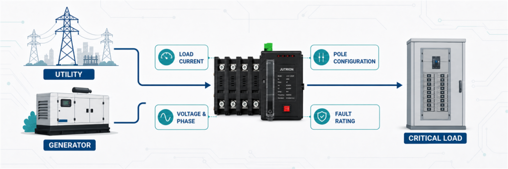
Uma chave de transferência automática deve suportar a corrente mais alta que pode passar por ela a partir de qualquer fonte. Calcule essa corrente a partir da carga transferida, não apenas a partir da etiqueta do gerador, e então selecione a próxima classificação adequada de ATS. Antes de fazer o pedido, confirme também tensão, fase, polos, comutação de neutro, suportabilidade a curto-circuito, método de transição, funções do controlador e a norma aplicável.
Um gerador de 100 kVA não exige automaticamente uma chave de transferência de 100 A. Em 400 V trifásico, 100 kVA correspondem a cerca de 144 A. Em 230 V monofásico, a mesma potência aparente corresponderia a cerca de 435 A. O valor de potência permaneceu o mesmo. A corrente não.
É por isso que o dimensionamento da chave de transferência automática começa com o diagrama unifilar e a carga sendo transferida. A classificação do gerador é uma entrada. Não é a resposta completa.
Primeiro Decida o Que o ATS Realmente Vai Conduzir
Antes de usar uma fórmula, desenhe um limite ao redor do lado da carga do ATS. Isso evita o erro de dimensionamento mais comum: calcular uma parte do sistema enquanto especifica a chave para outra.
Um ATS pode transferir:
- um serviço de baixa tensão inteiro ou quadro de distribuição principal;
- um barramento dedicado de emergência ou de segurança de vida;
- um subpainel de cargas selecionadas servindo bombas, iluminação, controles, refrigeração ou equipamentos de TI;
- uma máquina ou processo industrial;
- a saída de um gerador, inversor ou segunda fonte de concessionária.
Suponha que um edifício tenha um serviço principal de 800 A, mas apenas um quadro de cargas essenciais de 250 A seja respaldado. Um ATS instalado nesse quadro essencial não é automaticamente um dispositivo de 800 A. Seu requisito de corrente contínua segue o circuito transferido, sujeito às regras de projeto aplicáveis e ao arranjo dos dispositivos de proteção.
O problema oposto também ocorre. Um gerador pode ser menor que o serviço da concessionária, mas o ATS permanece no caminho da fonte normal e conduz continuamente a carga selecionada enquanto a energia da concessionária estiver disponível. Pode ser necessário corte de cargas ou um painel de cargas essenciais se o gerador não puder alimentar tudo conectado a jusante. A chave não pode fazer um gerador subdimensionado conduzir mais carga.
Monte a Planilha de Entradas de Dimensionamento Antes de Calcular
Um bom dimensionamento de ATS começa com uma lista curta de entradas verificadas. Se vários itens forem desconhecidos, marque-os como pontos em aberto em vez de escondê-los atrás de um grande fator de segurança. Superdimensionar a estrutura de amperes não pode corrigir um arranjo de neutro inadequado, uma baixa classificação de suportabilidade a falhas ou um controlador que não consegue se comunicar com o gerador.
| Entrada | Por que é importante | Onde verificar |
|---|---|---|
| Carga transferida | Define qual corrente o ATS deve conduzir | Lista de cargas, diagrama unifilar, demanda medida |
| Fontes normal e alternativa | Determina o arranjo das fontes e a sequência do controlador | Diagrama unifilar e dados do gerador/inversor |
| Tensão e frequência | Define requisitos de isolamento, detecção e controlador | Especificação do projeto e placas de identificação das fontes |
| Sistema monofásico ou trifásico | Altera a fórmula de corrente e a configuração dos polos | Desenhos de distribuição |
| Potência em A, kW ou kVA | Determina qual método de cálculo é válido | Lista de cargas, dados do gerador, placas de identificação dos equipamentos |
| Fator de potência e eficiência | Necessários ao converter certos valores de kW em corrente | Dados do equipamento ou do gerador |
| Cargas de motores e transformadores | Afeta a sequência de transferência, corrente de partida e resposta da fonte | Lista de motores e estudo de partida |
| Corrente de falta disponível | Define o desempenho exigido de suportabilidade e fechamento | Estudo de curto-circuito |
| Aterramento e projeto do neutro | Determina se um neutro sólido ou comutado é apropriado | Estudo de aterramento e regras locais de instalação |
| Ambiente e invólucro | Pode afetar a elevação de temperatura, redução de capacidade e série do produto | Dados do local e instruções do fabricante |
Para uma instalação existente, a demanda medida pode ser mais útil do que somar toda a carga nominal conectada. Uma planta pode ter 600 kW de equipamentos conectados, mas nunca operar todos simultaneamente. Por outro lado, uma medição curta feita durante um turno de produção leve pode subestimar o máximo real. Use um registro de demanda representativo, o cronograma de operação e a expansão planejada em conjunto.
Para uma nova instalação, o cronograma de cargas deve identificar quais cargas são contínuas, intermitentes, mutuamente exclusivas ou descartadas durante a operação do gerador. Este é o ponto onde o projeto elétrico e as prioridades operacionais se encontram. O ATS deve atender ao sistema de emergência pretendido, não a uma condição imaginária em que cada dispositivo conectado opera em plena carga para sempre.
Converta os Dados do Projeto Disponíveis em Amperes
Use a corrente diretamente quando uma corrente máxima de projeto verificada já estiver disponível. Se o projeto fornecer potência em kW ou kVA, converta-a usando a tensão correta do sistema e o arranjo de fases.
Quando a Entrada for em kVA
A potência aparente em kVA já inclui o efeito do fator de potência, portanto, não divida pelo fator de potência uma segunda vez.
Monofásico:
I = S × 1.000 / V
Trifásico:
I = S × 1.000 / (√3 × VLL)
Aqui, I é a corrente de linha em ampères, S é a potência aparente em kVA, V é a tensão monofásica, e VLL é a tensão trifásica linha a linha.
Quando a Entrada for em kW
A potência real requer uma suposição de fator de potência. Se o valor em kW for a saída mecânica de um motor, em vez da entrada elétrica, a eficiência também importa.
Carga elétrica monofásica:
I = P × 1.000 / (V × FP)
Carga elétrica trifásica:
I = P × 1.000 / (√3 × VLL × FP)
Para um motor especificado pela potência de eixo em kW, divida também pela eficiência. Use a corrente de placa sempre que possível, pois ela reflete o projeto real do motor melhor do que uma estimativa genérica de eficiência.
| Entrada disponível | O que usar | Erro comum |
|---|---|---|
| Corrente de carga verificada em A | Use a corrente de projeto diretamente | Convertê-la de volta em potência e adicionar novas suposições |
| Classificação do gerador ou carga em kVA | Use a fórmula de kVA para a fase e tensão corretas | Dividir pelo fator de potência duas vezes |
| Carga elétrica em kW | Use tensão, fase e um fator de potência justificado | Assumir FP = 1 para uma carga comercial ou industrial mista |
| Saída do motor em kW | Prefira a corrente de placa; caso contrário, inclua FP e eficiência | Tratar a saída mecânica como entrada elétrica |
| Apenas a classificação do disjuntor principal | Verifique se o ATS transporta o serviço completo ou um alimentador de cargas selecionadas | Copiar automaticamente o quadro do disjuntor principal para cada ATS |
Carga Conectada, Demanda Máxima e Capacidade da Fonte
Esses três valores podem ser diferentes, e cada um responde a uma pergunta distinta.
Carga conectada é a soma dos equipamentos que poderiam ser conectados. É útil para entender o sistema, mas pode superestimar a corrente simultânea quando as cargas operam em horários diferentes.
Demanda máxima é a carga simultânea mais alta e plausível sob a condição de operação definida. Este é frequentemente o ponto de partida mais relevante para o requisito de corrente contínua do ATS.
Capacidade da fonte é o que a concessionária, o gerador, o transformador, o inversor ou o sistema de baterias pode fornecer. A fonte alternativa pode ser deliberadamente menor do que a carga conectada quando os controles de prioridade descartam circuitos não essenciais.
Considere um hotel com 420 A de equipamentos conectados no lado de emergência. O estudo de operação mostra que bombas de incêndio, iluminação de evacuação, segurança e elevadores selecionados criam uma demanda máxima transferida de 285 A. O gerador é classificado para 350 A, e os controles impedem que o HVAC de conforto se conecte durante uma interrupção. Um ATS de 400 A pode ser um ponto de partida defensável. Somar todos os 420 A sem reconhecer a sequência de controle poderia empurrar o projeto para um quadro maior e mais caro. Usar apenas a classificação do gerador de 350 A perderia o motivo pelo qual o sistema funciona.
A sequência de gerenciamento de carga deve ser confiável e documentada. Se os controles falharem e todos os 420 A puderem se conectar, a fonte menor pode ser sobrecarregada, mesmo que o próprio ATS possa transportar a corrente. O dimensionamento do ATS e o dimensionamento do gerador estão conectados, mas não são o mesmo cálculo.
Três Exemplos Práticos de Dimensionamento de ATS
Exemplo 1: Um Painel de Cargas Essenciais Monofásico
Considere um exemplo ilustrativo de um pequeno site comercial com um painel de carga essencial monofásico de 230 V. A carga simultânea calculada é de 11,5 kVA.
I = 11,5 × 1.000 / 230 = 50 A
A corrente calculada é 50 A. A decisão de compra correta não é simplesmente “comprar um ATS de 50 A”. Verifique a carga contínua esperada pelas regras de instalação, as classificações disponíveis do produto, as classificações dos cabos e dispositivos de proteção, e qualquer crescimento de carga planejado. Se o requisito verificado exceder 50 A após essas verificações, um quadro de 63 A pode ser a seleção prática.
Um compacto interruptor de transferência automática JUTRION pode ser adequado para este tipo de aplicação de carga selecionada, mas o modelo exato ainda deve corresponder à tensão da fonte, arranjo de polos, lógica do controlador e condições de curto-circuito.
Exemplo 2: Um Gerador Trifásico de 100 kVA, 400 V
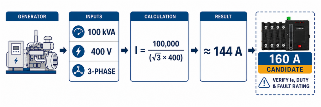
Cálculo de dimensionamento de ATS trifásico para um gerador de 100 kVA 400 V, resultando em aproximadamente 144 A.Um edifício comercial usa um gerador de reserva de 100 kVA a 400 V, trifásico. O ATS transfere um quadro de emergência dedicado que o gerador deve alimentar.
I = 100 × 1.000 / (√3 × 400)
I ≈ 144 A
Um ATS de 125 A seria muito pequeno para a saída de potência aparente nominal do gerador. A próxima classificação padrão adequada poderia ser 160 A, desde que o cálculo da carga transferida, o regime de operação, os dados do produto e as regras de instalação o suportem.
Agora mude uma suposição. Se a demanda máxima verificada do quadro de emergência for de apenas 105 A e o gerenciamento de carga impedir que circuitos adicionais se conectem durante a operação do gerador, o engenheiro pode dimensionar em torno dessa carga controlada em vez da saída teórica do gerador. Essa decisão deve ser documentada no projeto do sistema. Um fornecedor não deve inferi-la da placa de identificação do gerador.
Este caso também mostra por que um ATS pode ser classificado acima do gerador. Um interruptor de 160 A conectado a uma fonte capaz de 144 A não é inerentemente uma incompatibilidade. A classificação do interruptor é um limite de condução, não um comando que força 160 A do gerador.
O ATS Deve Corresponder ao Gerador ou ao Disjuntor Principal?
Não existe uma regra universal de “corresponder à placa de identificação maior”. Siga o caminho da corrente.
Se o ATS for instalado em um ponto de transferência de serviço completo, ele pode transportar a carga de serviço da fonte normal sempre que a concessionária estiver disponível. O gerador ainda pode ser menor se o sistema tiver gerenciamento de carga aprovado, mas o equipamento de transferência e a arquitetura de distribuição devem ser adequados ao caminho normal completo.
Se o ATS alimentar um quadro de carga essencial separado, sua classificação pode seguir a demanda calculada desse alimentador e as regras de projeto, em vez da classificação do serviço principal do edifício. Isso é comum quando apenas circuitos críticos exigem energia de reserva.
Se o ATS for empacotado com um gerador para uma máquina dedicada, a corrente do gerador, a demanda da máquina, o comportamento de partida e a proteção do alimentador podem estar todos próximos. Mesmo assim, verifique a tensão, fase, corrente de falta e interface do controlador em vez de selecionar apenas por kVA.
| Localização do ATS | Base primária de dimensionamento | Verificação secundária importante |
|---|---|---|
| Transferência de serviço completo | Corrente máxima através do caminho de serviço | Regras de serviço, gerenciamento de carga do gerador, corrente de falta |
| Subpainel de carga essencial | Demanda calculada dos circuitos selecionados | Proteção do alimentador e lógica de alívio de carga |
| Máquina ou processo dedicado | Corrente operacional da máquina | Regime de partida e interrupção aceitável |
| Interruptor de saída do gerador | Corrente nominal do gerador e carga transferida conectada | Proteção contra sobrecarga e planos futuros de paralelismo/fonte |
| Transferência concessionária-para-concessionária | Corrente de carga transportada de qualquer fonte da concessionária | Independência da fonte e permissão de transição |
Um ATS maior pode ser usado com um gerador menor quando as classificações elétricas e a proteção são coordenadas. Um ATS menor não pode ser justificado apenas porque o gerador é menor se o interruptor transporta uma carga maior do lado da concessionária durante a operação normal.
Exemplo 3: Um Barramento de Emergência Industrial com Muitos Motores
Um barramento de emergência industrial tem 180 A de carga em operação, incluindo bombas e motores de ventilação. Selecionar um ATS de 200 A pode parecer suficiente. A questão mais difícil é o que acontece durante a transferência.
Cargas de motores podem reter tensão após a desconexão. Se uma segunda fonte for conectada enquanto a tensão residual estiver fora de fase, o estresse elétrico e mecânico pode exceder as condições normais de operação. A tensão e frequência do gerador também podem cair quando vários motores reiniciam juntos.
Não resolva isso aplicando uma regra universal de “carga de motor × 1,5”. Esse atalho mistura três decisões diferentes:
- a corrente contínua que os contatos do ATS devem transportar;
- o dever de fechamento e utilização do equipamento de comutação;
- a capacidade do gerador de aceitar kVA de partida e queda de tensão.
Um projeto melhor pode usar reinicialização escalonada, alívio de carga, uma posição neutra de transição atrasada ou transferência em fase. Um atraso neutro pode permitir que a tensão residual de cargas indutivas decaia antes que a fonte alternativa seja conectada. O ATS e o controlador escolhidos devem suportar a sequência necessária.
Para este projeto, o quadro de amperagem não pode ser finalizado até que o estudo de partida de motores, a sequência de transferência, a resposta do gerador e a proteção a montante sejam revisados. A resposta preliminar honesta é “pelo menos o requisito de carga contínua verificado, depois confirme o dever de transferência.”
Como o Tipo de Carga Muda a Decisão Após o Cálculo de Amperagem
Dois projetos podem ter a mesma corrente em operação de 250 A e precisar de soluções de transferência diferentes. A diferença está no que a carga faz quando a tensão desaparece e retorna.
Aquecimento Resistivo e Iluminação
Cargas predominantemente resistivas geralmente têm uma relação direta entre potência e corrente. As principais questões são simultaneidade, regime contínuo e capacidade da fonte. Alguns sistemas de iluminação, no entanto, incluem drivers eletrônicos com alta corrente de inrush ou harmônica, então o rótulo “iluminação” não é suficiente.
Motores, Bombas, Compressores e Ventiladores
Os motores criam kVA de partida, tensão residual e possível estresse de ângulo de fase durante a transferência. O sistema pode reiniciar os motores sequencialmente em vez de todos ao mesmo tempo. Uma transição atrasada pode fornecer tempo para a tensão residual decair, enquanto os controles de transferência em fase podem aguardar uma relação de fase adequada. A abordagem correta depende do processo e do equipamento.
Transformadores
A energização do transformador pode produzir uma alta corrente de inrush magnetizante que varia com o fluxo residual e o ponto na forma de onda de tensão no fechamento. Uma transferência que é aceitável para a corrente de regime permanente do transformador ainda pode causar uma queda severa na tensão da fonte ou operação indesejada da proteção. Revise o estudo do transformador e do gerador em vez de aplicar uma margem de corrente genérica.
Cargas de UPS, Data Center e Eletrônicas
As cargas eletrônicas podem ser sensíveis ao tempo de interrupção e à qualidade da fonte. Elas também podem consumir corrente não linear. Um UPS pode cobrir uma lacuna de transição aberta, mas o gerador e o controlador do ATS devem permitir que a fonte alternativa se estabilize. Limiares de transferência muito estreitos podem causar comutação repetida quando a tensão ou frequência do gerador oscila próximo ao limite de aceitação.
Bombas de Incêndio e Cargas de Segurança de Vida
Esses sistemas são regidos por regras específicas de aplicação e requisitos do projeto. Eles não são alimentadores de motores comuns. A edição atual da IEC 60947-6-1:2026 inclui disposições específicas para equipamentos de comutação de transferência usados com equipamentos de controle de bombas de incêndio acionadas eletricamente. Trate o sistema aprovado completo, o controlador, a fonte e as regras de instalação em conjunto.
Selecione a Próxima Classificação de ATS Adequada, Não o Número Mais Próximo
Uma vez estabelecida a corrente de projeto, compare-a com as classificações de produto disponíveis. Nunca arredonde para baixo. Também evite superdimensionar sem motivo. Um ATS muito maior pode aumentar o tamanho do invólucro, os requisitos de terminação de cabos, o custo do painel e a carga de peças de reposição sem melhorar o desempenho do sistema.
| Corrente calculada | Próximo quadro possível | O que ainda deve ser verificado |
|---|---|---|
| 28 A | 32 A ou a próxima classificação oferecida | Serviço contínuo, coordenação de condutores e dispositivos de proteção |
| 50 A | 63 A onde exigido pela base de projeto verificada | Crescimento de carga, terminais, invólucro, configuração de polos |
| 144 A | 160 A | Carga real transferida, capacidade da fonte, classificação de falta |
| 365 A | 400 A | Temperatura, arranjo de barramento/cabo, regime de transferência |
| 420 A | 600 A | Arquitetura de comutação de alta corrente, proteção, estratégia de manutenção |
Esses são mapeamentos ilustrativos, não um substituto para um catálogo específico do modelo. A JUTRION oferece soluções de ATS em uma ampla faixa de corrente, mas disponibilidade, classe, polos, controlador e classificações de teste variam por série.
Verifique a Corrente Operacional Nominal e a Categoria de Utilização
O número impresso como quadro ou classificação de corrente térmica nem sempre é a corrente que o dispositivo pode comutar sob todas as condições de carga. Para um projeto IEC, verifique a corrente operacional nominal do modelo, Ie, na tensão do projeto e para a categoria de utilização aplicável.
Equipamentos de comutação de transferência IEC podem ser marcados com categorias como AC-31, AC-32 ou AC-33. A categoria reflete o tipo de carga e o regime de comutação usado para estabelecer a classificação. Cargas de motor e cargas indutivas mistas podem impor um regime de fechamento e abertura mais exigente do que cargas predominantemente resistivas. Um produto que carrega sua corrente de quadro total em uma categoria pode ter um Ie menor em outra.
Isso altera a sequência de seleção. Se o cálculo resultar em 365 A, um quadro nominal de 400 A é apenas um candidato. A tabela de dados relevante também deve mostrar um Ie de pelo menos 365 A na tensão do sistema e na categoria de utilização exigida. Se não mostrar, passe para um quadro maior ou um produto projetado para esse regime.
| Resultado do cálculo | Quadro preliminar | Próxima verificação decisiva |
|---|---|---|
| 50 A a 230 V monofásico | Candidato de 63 A | Ie a 230 V, regime de carga, polos e condição operacional contínua |
| 144 A a 400 V trifásico | Candidato de 160 A | Ie a 400/415 V para a categoria de utilização exigida |
| Carga pesada de motores de 365 A | Candidato de 400 A | Regime AC-33, sequência de reinício, resposta do gerador e dados do produto |
Esta é a ponte que falta entre um cálculo de sistema de potência e uma seleção real de catálogo. A fórmula produz uma corrente necessária. O Ie testado pelo fabricante confirma se um modelo específico pode executar esse regime.
Verifique Temperatura, Invólucro, Terminais e Regime de Instalação
A corrente de catálogo está vinculada às condições declaradas. Um comutador instalado em uma sala elétrica fria e ventilada não experimenta o mesmo ambiente térmico que um gabinete externo selado exposto ao sol, poeira, sal ou alta temperatura ambiente.
Confirme a faixa ambiente permitida e qualquer desclassificação do fabricante. Não presuma que escolher o próximo quadro garanta automaticamente corrente total em temperatura elevada. A construção do invólucro, ventilação, arranjo de barramentos, tamanho do cabo, número de condutores por terminal e calor interno de equipamentos adjacentes afetam a montagem final.
A capacidade do terminal merece atenção antecipada em projetos de alta corrente. Um ATS de 1.600 A pode exigir múltiplos cabos paralelos ou conexões em barramento por fase. O montador do painel precisa da faixa aprovada de condutores, arranjo de bornes, espaço para curvatura, direção de entrada, valores de torque e capacidade do neutro. Um disjuntor eletricamente adequado que não aceita os cabos especificados não é uma seleção utilizável.
A frequência de operação também importa. Um ATS usado apenas durante quedas ocasionais da concessionária tem um perfil de operação diferente de um site remoto gerador-a-gerador que alterna fontes em um cronograma. Dados de resistência mecânica e elétrica, acesso para manutenção, peças sobressalentes e requisitos de bypass tornam-se mais importantes conforme aumentam a frequência de transferência e o custo do tempo de inatividade.
A Corrente Nominal é Apenas o Primeiro Filtro
Uma corrente calculada corretamente ainda pode levar ao ATS errado. Complete as seguintes verificações antes de emitir uma especificação de compra.
1. Combine Ambas as Fontes para Tensão, Fase e Frequência
O ATS e seu controlador devem ser adequados para a fonte normal, fonte alternativa e carga. Confirme a tensão nominal, faixa de detecção permitida, arranjo monofásico ou trifásico, sequência de fases e frequência. Para fonte geradora, confirme que o controlador não transfere até que tensão e frequência estejam estáveis.
2. Decida se o Neutro Deve Ser Comutado
Um ATS trifásico de três polos comuta os condutores de fase e normalmente mantém o neutro sólido. Um ATS de quatro polos comuta o neutro como um polo com corrente nominal completa. Arranjos com neutro comutado são comumente considerados com fontes derivadas separadamente, mas “use 4P para todo gerador” não é uma regra universal segura.
A decisão depende do projeto de aterramento e conexão equipotencial, arranjo da fonte, proteção contra corrente residual, normas locais e comportamento dos caminhos de corrente do neutro em operação normal e de emergência. Peça ao projetista do sistema para confirmar este ponto. Não pode ser decidido apenas pela fórmula da corrente.
3. Escolha a Classe do Equipamento de Transferência e a Arquitetura de Proteção
Um disjuntor de transferência classe PC é primariamente um dispositivo de transferência. Geralmente depende de proteção contra sobrecorrente coordenada a montante. Um arranjo classe CB usa dispositivos de comutação baseados em disjuntores e pode integrar funções de interrupção de sobrecarga e curto-circuito, dependendo do conjunto testado.
Não selecione a classe apenas pela velocidade ou preço. Pergunte quem é responsável por eliminar uma falha a jusante, qual dispositivo de proteção está a montante e se a combinação completa possui as classificações necessárias. A linha JUTRION de MCCB, alta corrente e o guia do sistema ACB fornecem contexto útil para o lado protetivo dessa decisão. de MCCB e alta corrente guia do sistema ACB fornecem contexto útil para o lado protetivo dessa decisão.
4. Verifique as Classificações de Curto-Circuito IEC ou WCR UL
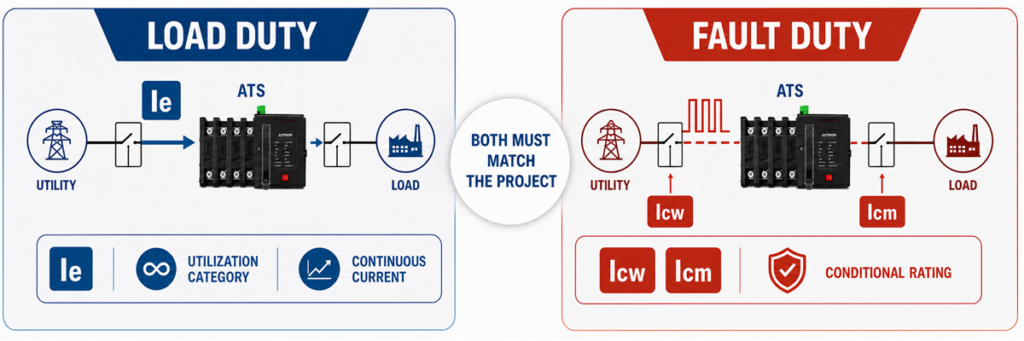
Comparação da corrente operacional nominal Ie da ATS com as classificações de curto-circuito Icw, Icm e classificação condicional.Uma corrente nominal de 400 A indica a carga que o ATS pode conduzir sob suas condições nominais. Não indica que o interruptor pode suportar uma falha de 50 kA no ponto de instalação.
Para um projeto IEC, revise os valores de curto-circuito indicados para o equipamento de transferência. Dependendo do produto e do arranjo de proteção, estes podem incluir corrente nominal de suporte por curto-circuito de curta duração Icw, capacidade nominal de fechamento em curto-circuito Icm, ou uma classificação condicional de curto-circuito vinculada a um dispositivo de proteção a montante especificado. O valor de tempo e as condições de proteção são tão importantes quanto o valor da corrente.
Para uma aplicação na América do Norte, a classificação de suporte e fechamento WCR deve ser adequada para a corrente de falha disponível no local do ATS sob as condições indicadas. Um WCR pode depender de um fusível ou disjuntor específico e seu tempo de eliminação.
Em ambos os sistemas, utilize as informações de coordenação específicas do modelo. A capacidade de interrupção impressa em um MCCB a montante não pode ser simplesmente copiada para a especificação do ATS; os dois dispositivos desempenham funções diferentes durante uma falha.
5. Selecione o Método de Transição ao Redor da Carga
Transição aberta é break-before-make: a primeira fonte se desconecta antes da segunda se conectar. Transição retardada adiciona um intervalo intencional de desligamento. Transição fechada paraleliza brevemente fontes aceitáveis e introduz controles adicionais e requisitos da concessionária.
A maioria das aplicações não escolhe o método de transição pela corrente nominal. Escolhem pelo comportamento da carga, tolerância à interrupção, tensão residual, resposta do gerador e regras de paralelismo de fontes.
6. Especifique o Controlador e as Interfaces do Projeto
Um sistema utilidade-gerador normalmente necessita de mais que detecção de tensão. Verifique contatos de partida e parada do gerador, atraso de partida, configurações de fonte disponível, atraso de transferência, atraso de retorno, tempo de resfriamento, operação manual, funções de teste, contatos de alarme e indicação remota.
Projetos industriais e de energia crítica podem também necessitar de comunicação RS485/Modbus, registro de eventos, alívio de carga, interfaces com sistema de incêndio ou arranjo de bypass-isolamento. Esses recursos podem alterar a série e o invólucro mesmo com a mesma corrente nominal.
Use Este Processo de Dimensionamento de ATS em Nove Etapas
- Marque o limite do ATS no diagrama unifilar. Identifique todos os circuitos que permanecem a jusante na operação normal e de emergência.
- Estabeleça a demanda máxima transferida crível. Use dados medidos ou uma programação de carga documentada, não uma soma inexplicada ou uma foto de carga leve.
- Converta potência em corrente corretamente. Distinga amperes, kW e kVA; use a fórmula correta para monofásico ou trifásico.
- Verifique a fonte alternativa. Confirme que o gerador, inversor ou segunda fonte de alimentação pode suprir a carga pretendida e a sequência de partida.
- Selecione a próxima corrente nominal adequada. Use a base de projeto verificada e os quadros de produto disponíveis. Nunca arredonde para baixo.
- Revise o comportamento da carga durante a transferência. Considere tensão residual de motores, inrush de transformadores, ride-through de UPS, alívio de carga e ordem de reinício.
- Complete a configuração elétrica. Especifique tensão, frequência, polos, tratamento do neutro, arquitetura PC/CB e método de transição.
- Verifique a coordenação de falhas e proteção. Compare a capacidade marcada de suportar e de fechamento com a corrente de falha disponível e o dispositivo de proteção a montante.
- Finalize a especificação do projeto. Adicione funções do controlador, comunicações, invólucro, terminais, condições ambientais, norma aplicável, quantidade e mercado de destino.
Esta sequência separa intencionalmente o cálculo da verificação. Permite que o comprador obtenha um dimensionamento preliminar rápido sem presumir que o resultado sozinho autoriza a instalação.
Mantenha o registro do cálculo junto com a cotação. No mínimo, registre a fonte dos dados de carga, a data ou condição operacional representada por quaisquer medições, as suposições de diversidade, a fórmula usada e o motivo da escolha da estrutura final. Se uma revisão posterior do projeto adicionar uma bomba, alterar a tensão do gerador ou mover o ATS para um ponto diferente no diagrama unifilar, a equipe pode ver imediatamente se o resultado original ainda é válido. Sem esse registro, um dimensionamento de estrutura frequentemente sobrevive a várias revisões de desenho mesmo após as suposições por trás dele terem mudado.
IEC 60947-6-1:2026 e UL 1008 Não São Etiquetas Intercambiáveis
A edição atual da IEC é IEC 60947-6-1:2026. Aplica-se a equipamentos de comutação de transferência usados para transferir cargas entre fontes de energia até 1.000 V AC ou 1.500 V DC. A edição de 2026 cobre equipamentos operados manualmente, remotamente e automaticamente, e adiciona tratamento específico para áreas incluindo equipamentos de bypass/isolation, ATSE de transição fechada, controladores ATS independentes e equipamentos de comutação de transferência para bombas de incêndio.
Para projetos na América do Norte, UL Solutions identifica UL 1008 como a norma usada para chaves de transferência automáticas em sistemas de emergência e standby opcionais, bem como chaves de transferência não automáticas. Os requisitos de instalação também dependem do código elétrico aplicável, classificação do projeto e autoridade competente.
Um cálculo de corrente é útil em qualquer mercado. Ele não prova que um ATS específico é certificado, listado ou aprovado para esse projeto. Confirme o modelo exato, norma, tensão, capacidade de interrupção de curto-circuito e condições de instalação antes de encomendar.
Por Que Dois ATS com a Mesma Capacidade de Amperagem Podem Não Ser Equivalentes
A capacidade em amperes é apenas uma linha na placa de identificação. Dois transfer switches de 400 A podem suportar a mesma corrente de carga normal enquanto usam mecanismos de comutação, arranjos de neutro, arquiteturas de proteção, controladores e capacidades de curto-circuito diferentes.
Cinco verificações revelam a maioria das diferenças significativas:
- Arquitetura de transferência: Um dispositivo classe PC normalmente depende de proteção coordenada a montante, enquanto um projeto classe CB usa comutação baseada em disjuntor e pode incluir funções de sobrecorrente.
- Número de polos: Uma unidade tripolar normalmente mantém o neutro sólido. Uma unidade tetrapolar comuta o neutro e deve ser compatível com o projeto de aterramento.
- Desempenho em faltas: A capacidade nominal de suportar curto-circuito e de fechamento deve corresponder à corrente de falta disponível e ao dispositivo de proteção a montante especificado.
- Funções do controlador: Sensoriamento de fonte, contatos de gerador, atrasos ajustáveis, registros de eventos, comunicação e funções de controle de carga variam amplamente.
- Evidência aplicável: Tensão, categoria de utilização, condições ambientais, requisitos IEC ou UL e documentação de teste específica do modelo devem corresponder ao projeto.
Estas são diferenças de sistema, não extras opcionais de venda. Um ATS básico classe PC pode ser a resposta correta para um painel de distribuição coordenado. Uma instalação crítica pode precisar de transição retardada, monitoramento avançado ou isolamento por bypass. Nenhum produto é automaticamente melhor por ter mais funções. O dispositivo correto é aquele cuja configuração testada corresponde ao diagrama unifilar e sequência operacional.
Registre o Resultado como uma Especificação Preliminar Completa
Após o cálculo, anote as suposições e as verificações restantes. Uma especificação preliminar deve identificar a carga transferida, corrente calculada, estrutura proposta, tensão, fase, frequência, arranjo da fonte, polos, método de transição, arquitetura de proteção, interfaces do controlador, ambiente de instalação e norma aplicável.
Esse registro facilita a revisão de engenharia e evita que um dimensionamento de estrutura fique separado das suposições por trás dele. Também cria uma transição clara entre o projetista do sistema, montador do painel, fornecedor do gerador e fabricante do ATS.
Uma vez confirmadas essas entradas, compare-as com as configurações disponíveis no catálogo. gama de chaves de transferência automática JUTRION. A seleção final do modelo deve basear-se nas capacidades específicas do modelo e nas condições do projeto, não apenas na corrente.
A ordem prática é simples: defina o que o ATS irá suportar, calcule a corrente, verifique Ie para a categoria de utilização real e então complete as verificações de polos, transição, controlador e curto-circuito.
Referências Técnicas
