

Qual o tamanho de Contator AC que eu preciso? Relação kW para Amperes do motor, classificações AC-1 a AC-4 e seleção da bobina
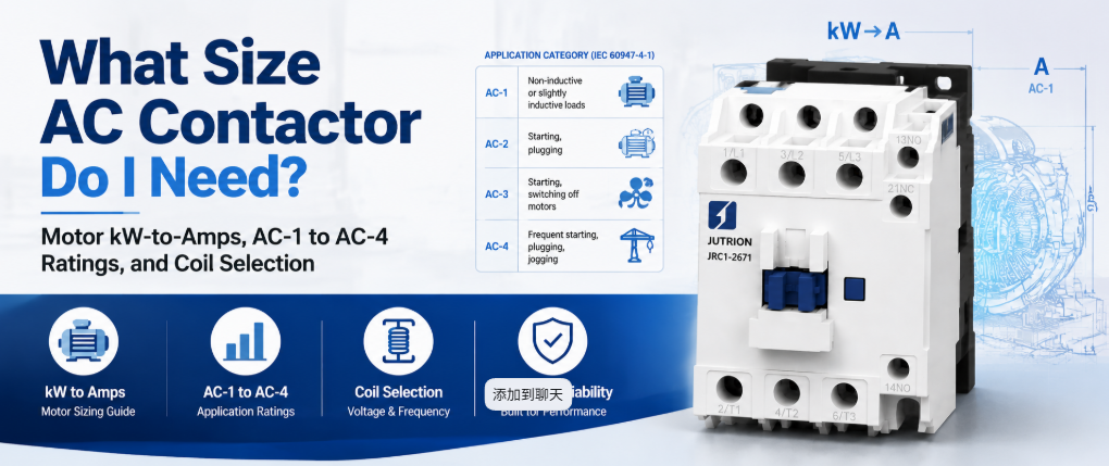
Resposta Rápida: O Que Faz um Contator AC?
Um contator AC é um interruptor controlado eletricamente que utiliza um eletroímã acionado por bobina para fechar e abrir um circuito de potência sob comando, sendo projetado para realizar isso milhares a milhões de vezes sem que os contatos se soldem ou desgastem. Ele comuta a corrente de carga quando solicitado. Não protege o circuito. Dimensioná-lo corretamente significa dimensioná-lo conforme a classificação que se aplica ao seu dever real de carga, não pelo maior número impresso na etiqueta.
Um contator marcado como 20 A não é um dispositivo de 20 A para um motor. A mesma unidade física pode ser classificada para 20 A para um aquecedor resistivo e 9 A para um motor de gaiola de esquilo, porque a corrente de partida do motor e a interrupção indutiva castigam os contatos com muito mais força do que um aquecedor. Essa única distinção causa mais falhas prematuras de contatores do que qualquer outro erro de seleção.
Este guia cobre o que o contator deve suportar, como calcular isso, qual categoria de utilização se aplica e as verificações de polos, bobina, auxiliares, vida útil e coordenação que seguem o valor em ampères.
Combine o trabalho de comutação com o dispositivo correto
Antes de dimensionar qualquer coisa, confirme que um contator é o dispositivo correto para o trabalho. Projetos de painéis frequentemente falham porque se espera que um componente execute duas funções não relacionadas.
| Dispositivo | Função principal | Frequência de comutação | Desarma em falha |
|---|---|---|---|
| Contator AC | Abre e fecha a corrente de carga sob comando | Projetado para ciclos frequentes | Não. Requer um relé de sobrecarga ou disjuntor separado |
| Relé de uso geral | Comutação de baixa potência e controle de sinal | Classificado para serviço mais leve | Não |
| MCB ou MCCB | Proteção contra sobrecorrente e curto-circuito | Operação ocasional, não ciclos de rotina | Sim |
| Partida de motor | Contator e relé de sobrecarga em um único conjunto | Igual ao contator | Sim, através do relé de sobrecarga |
| Soft starter ou VFD | Rampa controlada da corrente do motor | Controle contínuo em vez de liga/desliga | Varia conforme o modelo |
Se a pergunta é como comutar uma carga ligada e desligada repetidamente sob comando, a resposta é um contator. Se a pergunta é o que protege o circuito contra sobrecarga, esse é um dispositivo diferente. Tratar o contator como se fizesse ambos é um dos erros mais comuns no projeto de painéis.
Por que um relé ou um disjuntor não pode ocupar o seu lugar
Um relé de uso geral pode fechar um circuito, mas não é construído para fazer isso em níveis de corrente de motor ou aquecedor a longo prazo. Os contatores são classificados para vida mecânica na casa dos milhões de operações, enquanto os relés de uso geral são classificados para uma pequena fração disso sob carga elétrica real. A diferença está no material dos contatos, na força da mola e na supressão de arco. Os contatores usam a geometria dos contatos e, em estruturas maiores, as câmaras de extinção de arco necessárias para interromper a corrente indutiva do motor repetidamente sem que os contatos sofram corrosão por arco ou soldem. Um relé forçado a esse serviço geralmente falha soldando fechado sob carga, o que é um modo de falha muito pior do que o desgaste gradual de um contator.
Um disjuntor é projetado para proteger um circuito e ser operado ocasionalmente, não para ser ciclado como parte da lógica normal de automação. Usar um disjuntor como chave de serviço encurta sua vida útil de proteção e não é para isso que ele é classificado. O contator e o dispositivo de proteção fazem dois trabalhos diferentes e pertencem juntos ao mesmo circuito.
Como Funciona um Contator AC
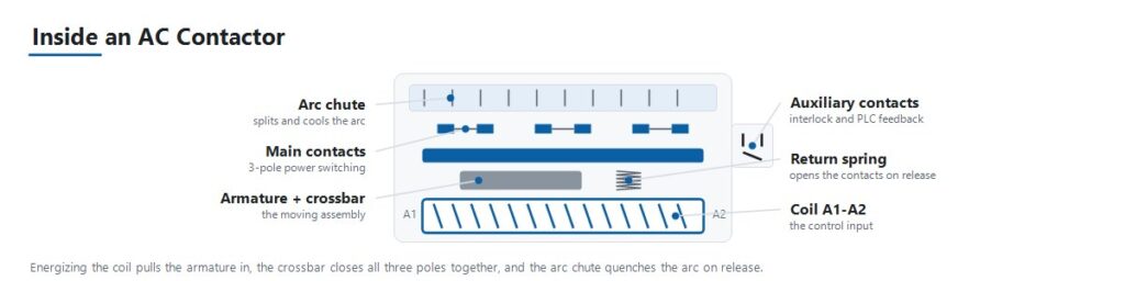
A sequência de operação explica a maioria dos modos de falha abordados mais adiante neste guia.
- O sinal de controle energiza a bobina. Um circuito de controle, como uma saída de PLC, termostato ou lógica de botoeira, aplica tensão à bobina em sua tensão nominal de bobina.
- O eletroímã atrai a armadura. A bobina energizada cria um campo magnético que atrai uma armadura móvel em direção a um núcleo fixo.
- Os contatos principais fecham. O movimento da armadura fecha os contatos principais de potência por meio de uma barra transversal comum, conectando a carga à alimentação.
- Os contatos auxiliares mudam de estado. Pequenos contatos auxiliares ligados à mesma armadura abrem ou fecham em sincronia com os contatos principais. Eles fornecem intertravamento, indicação e confirmação a um PLC de que o contator realmente fechou.
- A força da mola mantém a pressão de contato. A pressão de contato estável sob vibração e carga é o que evita o repique dos contatos e o aquecimento resistivo na face de contato.
- Desenergizar a bobina abre o circuito. Quando o sinal de controle cai, o campo magnético colapsa e uma mola de retorno puxa a armadura de volta, abrindo os contatos principais.
- A supressão de arco lida com a interrupção. Abrir um circuito sob carga, especialmente uma carga de motor indutivo, gera um arco entre os contatos que se separam. A geometria dos contatos e as câmaras de extinção de arco extinguem esse arco com rapidez suficiente para evitar danos em cada ciclo.
As Categorias de Utilização Decidem a Classificação Real de Corrente
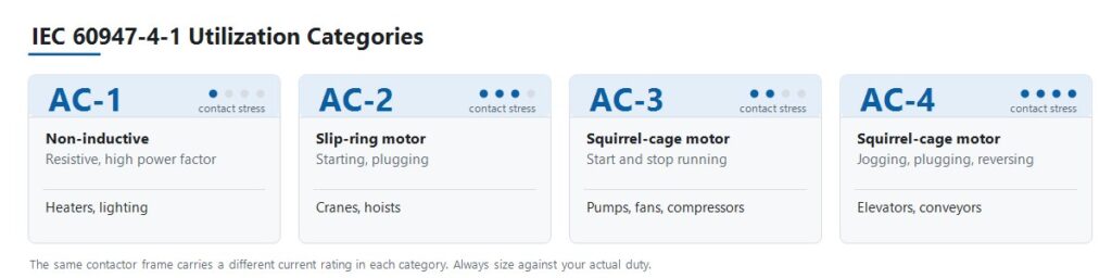
A IEC 60947-4-1 define categorias de utilização que descrevem o quão severa é uma carga sobre os contatos, não simplesmente quantos ampères ela consome. Este é o passo ao qual a maioria dos erros de seleção remonta.
| Categoria | Tipo de carga | Regime de comutação | Aplicação típica |
|---|---|---|---|
| AC-1 | Não indutiva ou levemente indutiva, alto fator de potência | Sem corrente de partida significativa | Aquecedores resistivos, bancos de aquecimento HVAC, iluminação geral |
| AC-2 | Motores de anel deslizante (rotor bobinado) | Partida e frenagem por inversão sob carga | Guindastes, talhas |
| AC-3 | Motores de gaiola de esquilo | Partida e desligamento de um motor em funcionamento | Bombas, ventiladores, compressores |
| AC-4 | Motores de gaiola de esquilo | Operação por impulsos, frenagem por inversão, reversão rápida | Elevadores, transportadores, máquinas-ferramenta |
A consequência é que um único contator possui várias classificações de corrente diferentes. Um JUTRION JRC1-D09 é classificado para 20 A na categoria AC-1 e 9 A na categoria AC-3. Ambos os valores descrevem o mesmo dispositivo físico. Dimensionar uma bomba com base no valor de 20 A coloca o contator em mais do que o dobro de sua classificação para serviço com motor, e os contatos mostrarão isso.
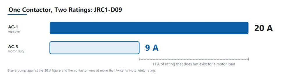
Leia cada classificação publicada juntamente com a categoria à qual ela pertence. Uma estrutura não é um modelo de guindaste nem um modelo de operação por impulsos. É uma única estrutura com várias classificações, e o regime decide qual classificação se aplica ao projeto.
Converta os Dados do Motor em Ampères
Use diretamente uma corrente de plena carga verificada quando o projeto já fornecer uma. Quando os dados forem fornecidos como potência do motor, converta-os usando a tensão e o arranjo de fases corretos.
Motores Trifásicos
I = P × 1.000 / (√3 × VLL × cos φ × η)
Cargas Monofásicas
I = P × 1.000 / (V × cos φ × η)
Aqui, I é a corrente de linha em ampères, P é a potência nominal de saída do motor em kW, VLL é a tensão trifásica de linha para linha, V é a tensão monofásica, cos φ é o fator de potência, e η é a eficiência.
O fator de potência para motores de indução padrão normalmente varia entre 0,80 e 0,88, e a eficiência entre 0,85 e 0,93 dependendo da classe de eficiência. Use os valores da placa de identificação sempre que disponíveis. As faixas típicas são para trabalho preliminar antes da chegada da ficha técnica do motor.
Para cargas monofásicas puramente resistivas, como elementos de aquecimento, o fator de potência e a eficiência são efetivamente unitários, e a expressão se reduz a I = P × 1.000 / V.
A Calculadora de dimensionamento de contator AC JUTRION realiza o mesmo cálculo e retorna uma corrente operacional mínima AC-3. É um ponto de partida para a especificação, não um substituto para a placa de identificação do motor ou para as tabelas de classificação do fabricante.
Aplicar os Multiplicadores de Tipo de Carga e a Redução por Temperatura Ambiente
Certas cargas consomem muito mais do que sua corrente em estado estacionário no momento da comutação. A prática industrial de longa data aplica um multiplicador para considerar esse comportamento. Essas convenções não são valores definidos na IEC 60947-4-1, portanto, trate-as como uma primeira aproximação e confirme-as com dados reais de corrente de inrush para circuitos críticos ou de grande porte.
| Tipo de carga | Multiplicador convencional | Razão |
|---|---|---|
| Bancos de capacitores | Aproximadamente 1,5 × corrente nominal do capacitor | O inrush capacitivo na energização é severo e muito curto |
| Transformadores e conjuntos de solda | Aproximadamente 2 × corrente nominal | O inrush de magnetização pode atingir muitas vezes a corrente em estado estacionário |
| Iluminação de descarga de gás e HID | Aproximadamente 1,1 a 1,4 × corrente nominal | Inrush do reator e comportamento de aquecimento |
| Refrigeração deficiente ou invólucro densamente compactado | 110 a 120 por cento da corrente nominal da carga | Temperatura interna elevada reduz a capacidade de corrente |
| Motor em funcionamento contínuo, serviço prolongado | Corrente nominal do contator reduzida em aproximadamente 30 por cento | Carga térmica sustentada nos contatos |
Condições de Temperatura Ambiente e do Invólucro
A corrente nominal de um contator pressupõe a temperatura ambiente de referência indicada em sua folha de dados. Acima dessa temperatura, a capacidade de condução de corrente diminui, mas a inclinação da redução é específica do fabricante e do quadro. Use a curva de redução da documentação real do produto, em vez de uma porcentagem genérica.
Duas condições se aplicam independentemente do produto. Primeiro, baseie o cálculo na temperatura dentro do invólucro, não na sala. Um painel densamente compactado em uma planta quente opera consideravelmente mais quente que o ambiente. Segundo, contatores montados lado a lado sem espaçamento aquecem uns aos outros, portanto, respeite o espaçamento mínimo do fabricante ou reduza ainda mais.
Um Exemplo Prático: Motor de Bomba de 4 kW a 400 V
Um motor de bomba centrífuga trifásica em um painel OEM de tratamento de água. Serviço padrão de partida e parada, aproximadamente 20 partidas por hora, ambiente do painel em torno de 35 °C.
Etapa 1. Estabelecer a categoria de utilização. Um motor de indução de gaiola de esquilo, iniciado e parado normalmente, é da categoria AC-3. Não é AC-1, mesmo que a carga seja descrita como uma simples bomba.
Etapa 2. Calcular a corrente de plena carga. Os valores da placa de identificação são 4 kW, 400 V, cos φ = 0,85, η = 0,90.
I = 4 × 1.000 / (1,732 × 400 × 0,85 × 0,90)
Calculando o denominador: 1,732 × 400 = 692,8, depois × 0,85 = 588,9, depois × 0,90 = 530,0.
I = 4.000 / 530,0 ≈ 7,6 A
Etapa 3. Selecionar com base na classificação AC-3. O requisito é um contator cuja classificação AC-3 cubra 7,6 A com margem. O JRC1-D09 é classificado para 9 A em AC-3, oferecendo aproximadamente 18 por cento de folga sobre a corrente nominal calculada. Note o que não foi feito: o mesmo JRC1-D09 suporta uma classificação AC-1 de 20 A, e dimensionar esta bomba com base nesse valor seria o erro mais comum na seleção de contatores.
Etapa 4. Verificar ambiente e serviço. A 35 °C de ambiente do painel com 18 por cento de folga, verifique o valor contra a curva de redução do produto antes de se comprometer. Essa margem é confortável em um painel bem ventilado e mais apertada em um densamente compactado. A 20 partidas por hora, confirme que as operações classificadas por hora e a vida elétrica AC-3 excedem confortavelmente o serviço esperado ao longo da vida útil do painel.
Etapa 5. Especificar a tensão da bobina. O secundário do transformador de controle do painel é 220 V AC, portanto a bobina é especificada para 220 V. Não é 400 V, mesmo que o motor opere a 400 V.
Etapa 6. Adicionar proteção. Combine o contator com um relé de sobrecarga corretamente dimensionado, ajustado para a corrente de plena carga do motor, e confirme a coordenação Tipo 1 ou Tipo 2 com o disjuntor ou fusível a montante. Uma partida normal abaixo de 10 segundos aponta para uma classe de disparo Classe 10 aqui. A calculadora de ajuste do relé de sobrecarga converte a corrente da placa de identificação, o fator de serviço e a duração da partida em um ajuste preliminar e classe de disparo.
Resultado: um JRC1-D09, tripolar, com bobina 220 V AC, mais um relé térmico. A seleção foi derivada da carga, não de um catálogo.
O mesmo procedimento se aplica para potências maiores. Um motor de 18,5 kW a 400 V resulta em aproximadamente 35 A de corrente nominal e requer um contator com classificação AC-3 acima desse valor.
Use Este Processo de Seleção de Contator AC em Sete Etapas
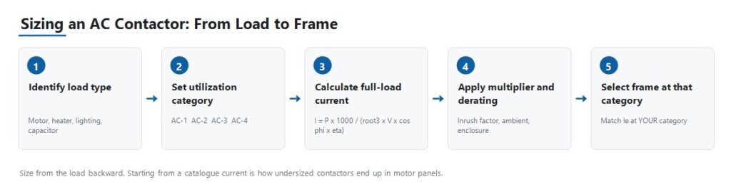
Etapa 1: Identificar o Tipo de Carga e a Categoria de Utilização
Estabeleça se a carga é resistiva, um motor padrão de gaiola de esquilo, um motor de rotor bobinado iniciando sob carga, ou um motor sujeito a joggamento e reversão. Tudo a jusante depende dessa resposta, porque ela determina qual das várias classificações de corrente do contator realmente se aplica.
Etapa 2: Calcular a Corrente Operacional e Confirmar a Tensão
Use as fórmulas acima para obter a corrente de plena carga, aplique o multiplicador de tipo de carga relevante e, em seguida, confirme que a corrente operacional classificada Ie do contator na sua categoria de utilização cobre isso com margem. Combine a tensão operacional classificada Ue à tensão de linha do sistema.
Etapa 3: Selecione a Tensão da Bobina
A tensão da bobina é uma especificação separada da tensão da carga. Um circuito de motor de 380 V pode ser comutado por uma bobina de 24 V DC ou 220 V AC dependendo da arquitetura de controle. Confirme o que o circuito de controle realmente fornece, seja uma saída PLC, um secundário de transformador de controle ou uma fonte de controle DC, antes de encomendar.
Etapa 4: Escolha o Número de Polos e a Configuração
Três polos é o padrão para cargas de motores trifásicos. Quatro polos é usado onde é necessário comutação de neutro ou um circuito independente adicional. Confirme o arranjo em relação ao projeto de aterramento do sistema, pois a comutação de neutro é necessária em alguns sistemas e desnecessária ou proibida em outros.
Etapa 5: Especifique os Contatos Auxiliares
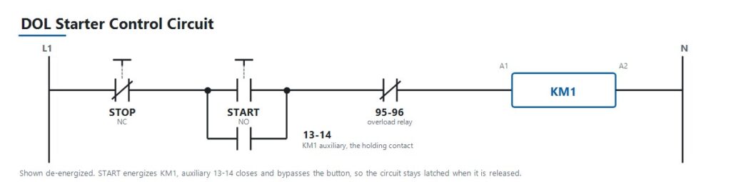
Determine quantos contatos auxiliares normalmente abertos e normalmente fechados são necessários para intertravamento, feedback de status para CLP e lâmpadas indicadoras, e se eles são integrais ou adicionados como um bloco auxiliar separado. Em uma partida direta padrão, um contato auxiliar ligado em paralelo com o botão de partida é o que mantém o circuito de controle, fazendo com que o contator permaneça energizado após o operador soltar o botão. Contatos auxiliares são baratos de especificar na fase de projeto e difíceis de adaptar posteriormente.
Etapa 6: Verifique a Vida Elétrica em Relação ao Ciclo de Trabalho Real
Para aplicações com ciclos frequentes, como jogging, reversão ou sequências de automação de alta frequência, verifique as operações nominais por hora e a vida elétrica na sua categoria de utilização. A vida mecânica, medida sem carga, é sempre o valor mais alto e menos relevante.
Etapa 7: Coordene com a Proteção a Montante
Combine o contator com um relé de sobrecarga dimensionado corretamente para cargas de motor e, em seguida, coordene com um disjuntor ou fusível a montante dimensionado para proteção contra curto-circuito. Em painéis de distribuição maiores, esse dispositivo a montante é frequentemente um disjuntor de ar. A seleção do contator é um elo em uma cadeia que vai da corrente de carga, à classificação do disjuntor, à corrente de falta presumida, ao poder de interrupção do dispositivo. Escolher o contator certo enquanto deixa essa cadeia não verificada apenas realoca o problema.
Classificações IEC 60947-4-1 e NEMA Não São Rótulos Intercambiáveis
Contatores AC vendidos internacionalmente são geralmente fabricados conforme IEC 60947-4-1, que define as categorias de utilização e a estrutura de classificação usada neste guia. A quinta edição atual foi publicada em 2023 e substitui a edição de 2018. Vale a pena verificar qual edição a especificação do projeto referencia, pois não são idênticas.
Os mercados norte-americanos comumente referenciam classificações de contatores NEMA ICS 2 em vez de, ou junto com, as categorias de utilização IEC. Os dois sistemas classificam contatores de forma diferente, pois a NEMA usa classes de tamanho em vez de AC-1 a AC-4. Uma especificação escrita para um mercado não se traduz automaticamente para o outro. Ao fornecer para um projeto norte-americano, confirme qual estrutura a especificação do comprador realmente exige antes de cotar uma peça.
Trate o padrão do produto, o código de instalação e qualquer requisito específico do mercado como três perguntas separadas. Confirmar um não responde aos outros.
Coordenação Tipo 1 e Tipo 2
A coordenação de curto-circuito sob a IEC 60947-4-1 determina quanto dano uma falta causa ao contator e à partida. O Tipo 1 permite danos ao equipamento após uma falta de curto-circuito, desde que o dano seja contido e não resulte em perigo, e o equipamento possa exigir reparo ou substituição. O Tipo 2 exige que o equipamento permaneça adequado para uso posterior, permitindo apenas leve soldagem de contatos. Esses são resultados comerciais e de engenharia diferentes. Confirme qual o projeto especifica antes de selecionar a combinação.
Escolhendo Entre as Classificações JUTRION JRC1
A JUTRION fabrica o Contator AC série JRC1 em suas próprias linhas de produção em Wenzhou, Zhejiang, fabricado conforme IEC 60947-4-1. Opções de tensão de bobina incluem 24 V, 48 V, 110 V, 220 V e 380 a 415 V em 50 ou 60 Hz. Cada unidade é testada quanto à operação mecânica, desempenho da bobina e comutação elétrica antes do envio.
A seguir estão os pontos de classificação publicados nas quatro categorias de utilização. Leia a tabela por categoria em vez de por modelo, pois o mesmo quadro aparece em mais de uma categoria com uma classificação diferente.
| Categoria | Ponto de classificação | Serviço que isso representa |
|---|---|---|
| AC-1 | JRC1-D09, 20 A | Aquecedores resistivos, bancos de aquecimento HVAC, iluminação geral |
| AC-2 | JRC1-D25, 25 A | Motores de rotor bobinado partindo sob carga, guindastes e talhas |
| AC-3 | JRC1-D09, 9 A | Motores de gaiola de esquilo, partida e parada normais, bombas e ventiladores |
| AC-4 | JRC1-D18, 7,7 A | Jogging, plugging, reversão rápida, elevadores e transportadores |
O JRC1-D09 aparece duas vezes, a 20 A sob AC-1 e 9 A sob AC-3, porque essas são duas classificações do mesmo contator físico sob dois serviços diferentes. Para um circuito padrão de motor de indução, que cobre a maioria das aplicações de bombas, ventiladores e compressores, dimensione conforme a classificação AC-3, como mostrado no exemplo prático. Para serviço de jogging ou reversão, dimensione conforme AC-4, onde o mesmo quadro suporta substancialmente menos corrente.
Classificações de quadro acima desses pontos publicados estão disponíveis. A seleção final do modelo deve ser baseada nas classificações específicas do modelo e nas condições do projeto, não apenas em um valor de corrente.
Aplique a Lógica de Seleção a Cinco Cenários de Painel
Painel de Motor Padrão para Bombas, Ventiladores e Compressores
Um OEM que constrói painéis de controle para equipamentos de HVAC ou tratamento de água especifica contatores para serviço simples de partida e parada de motor. Isso é categoria AC-3. Dimensione a classificação AC-3 em relação à corrente de plena carga calculada, combine com um relé de sobrecarga dimensionado corretamente e ajuste a tensão da bobina à saída do transformador de controle do painel.
Painel de Guindaste ou Talha com Motores de Rotor Bobinado
Um OEM de guindastes exige contatores que suportem partida com alto torque e serviço de frenagem por plugging em motores de rotor bobinado, o que é a categoria AC-2. Essas cargas são mais severas para os contatos do que o serviço padrão AC-3 devido às partidas repetidas sob carga e à reversão. O subdimensionamento aqui aparece como desgaste prematuro dos contatos, em vez de falha imediata, o que facilita o diagnóstico incorreto como um problema de qualidade.
Controle de Elevador ou Transportador com Jogging e Reversão
Um construtor de máquinas precisa de contatores para uma aplicação com reversão frequente de direção e movimentos de aproximação incremental, o que é a categoria AC-4, a mais exigente das quatro. A vida elétrica na taxa real de operações por hora importa mais aqui do que em qualquer outro cenário. Subdimensionar esta categoria é a maneira mais rápida de consumir a vida nominal de um contator.
Comutação de Banco de Capacitores para Correção de Fator de Potência
Uma instalação que adiciona capacitores de correção de fator de potência precisa de contatores dimensionados contra a corrente de inrush capacitiva, convencionalmente cerca de 1,5 vezes a corrente nominal do capacitor, e frequentemente especificados com resistores de pré-carga ou como contatores dedicados de comutação de capacitores. O dimensionamento padrão AC-1 não é adequado, porque a inrush capacitiva é um serviço de comutação distinto, em vez de uma versão suave do serviço resistivo.
Painel de Aquecimento Resistivo ou Iluminação
Um montador de painéis que comuta bancos de aquecimento HVAC ou grandes cargas de iluminação está trabalhando na categoria AC-1, a menos exigente, pois não há inrush significativo ou pico indutivo a gerenciar. Descarga e iluminação HID são exceções e requerem o multiplicador de 1,1 a 1,4 para o inrush do reator. Este também é o caso onde compradores às vezes especificam em excesso escolhendo uma peça classificada para AC-3 onde AC-1 seria suficiente, o que não é inseguro, apenas custo desnecessário.
Evite os Nove Erros que Causam Falha Precoce em Contatores
| Erro | Consequência | Prevenção |
|---|---|---|
| Dimensionamento contra a classificação AC-1 para uma carga de motor | Contator subdimensionado para seu dever real, contatos soldam ou desgastam prematuramente | Sempre dimensione contra a classificação para a categoria de utilização real |
| Omitindo o relé de sobrecarga | Motor e contator ambos expostos a sobrecorrente sustentada | Associe cada circuito de motor a um relé de sobrecarga corretamente dimensionado |
| Ignorando a frequência de comutação contra a vida elétrica | Um contator corretamente dimensionado em corrente ainda falha cedo em serviço de ciclo alto | Verifique operações classificadas por hora e vida elétrica na sua categoria |
| Tensão de bobina incompatível | Contator falha ao atrair, ou a bobina queima | Confirme contra a tensão real do circuito de controle, não a tensão da carga |
| Sem verificação de coordenação a montante | Uma falha de curto-circuito destrói o contator desnecessariamente | Verifique a coordenação Tipo 1 ou Tipo 2 antes de finalizar o projeto |
| Contatores de reversão sem intertravamento | Ambos os contatores podem fechar juntos, criando um curto fase-fase | Especifique intertravamento mecânico e elétrico em pares de reversão |
| Ignorando a temperatura ambiente e a redução de capacidade do invólucro | Vida útil reduzida apesar de todas as outras especificações estarem corretas | Reduza a capacidade usando a curva do produto e a temperatura do invólucro |
| Esquecendo o multiplicador do tipo de carga | Inrush de capacitor, transformador ou iluminação degrada os contatos ao longo do tempo | Aplique o multiplicador convencional para o tipo de carga |
| Especificando contatos auxiliares tarde demais | Retrabalho caro no painel ou blocos adicionais inconvenientes | Determine as necessidades de intertravamento e feedback na fase de projeto |
Instale, Comissione e Diagnostique o Contator
A maioria das falhas de contator relatadas como defeitos de produto são sintomas de um problema de dimensionamento, coordenação ou fornecimento de controle. A tabela abaixo mapeia os sintomas comuns para as verificações que identificam a causa.
| Sintoma | Causas possíveis | Verificações úteis |
|---|---|---|
| Vibra ou produz um zumbido intenso | Tensão de bobina baixa ou instável, anel de sombreamento desgastado, núcleo magnético sujo ou solto | Meça a tensão da bobina sob carga, inspecione a face do núcleo, verifique a estabilidade do fornecimento de controle |
| Contatos soldados | Subdimensionado para a categoria real, evento de curto-circuito sem coordenação adequada, frequência de comutação excessiva | Verifique o dimensionamento da categoria, revise o histórico de falhas a montante, compare operações por hora contra a vida elétrica classificada |
| Sem atração embora o sinal de controle esteja presente | Bobina em circuito aberto, tensão de bobina errada, travamento mecânico, fusível de controle queimado | Meça a resistência e a tensão da bobina nos terminais, verifique o fusível de controle, inspecione obstruções |
| Contatos picados ou queimados | Desgaste normal de fim de vida, subdimensionado para a categoria de dever, supressão de arco pobre em alta frequência de comutação | Compare a condição contra a vida elétrica classificada, re-verifique o dimensionamento da categoria, inspecione a calha de arco |
| Feedback auxiliar discorda do estado do contato principal | Bloco auxiliar desgastado ou desalinhado, desgaste da ligação mecânica | Teste a continuidade auxiliar independentemente, inspecione a ligação ao conjunto de contato principal |
| Terminais superaquecendo | Terminação solta, condutor subdimensionado, torque incorreto na instalação | Verifique o torque do terminal conforme a especificação, confirme a bitola do condutor, faça imagem térmica sob carga |
| Bobina queima repetidamente | Sobretensão sustentada no circuito de controle, temperatura ambiente excessiva, travamento mecânico impedindo a atração total | Meça a tensão de controle em todas as condições de operação, verifique travamento, confirme a temperatura ambiente |
Falhas precoces repetidas na mesma aplicação quase sempre indicam um erro de dimensionamento, coordenação ou ciclo de trabalho, e não um lote defeituoso. Diagnostique a causa antes de reencomendar o mesmo número de peça.
Proteja a Bobina e o Que a Aciona
Desenergizar uma bobina indutiva produz um transiente de tensão. Quando uma saída transistor de PLC, um pequeno relé intermediário ou um controlador eletrônico comuta essa bobina diretamente, o transiente retorna para ele. Esta é uma causa rotineira de falhas na saída do PLC e de contatos corroídos em relés intermediários, e é simples de evitar no projeto. Use um snubber RC em bobinas AC, e um diodo flyback ou varistor em bobinas DC. Note a compensação: um diodo flyback simples prolonga perceptivelmente o tempo de desligamento, o que importa quando o contator faz parte de uma função de parada relacionada à segurança com tempo de resposta especificado.
Confirme a tolerância de tensão de operação da bobina em vez de assumir que o valor nominal é válido. Um cabo de controle longo ou um transformador de controle subdimensionado podem colocar a tensão real da bobina abaixo da faixa na qual ela atrai e mantém, e o sintoma aparece como vibração, e não como uma falha óbvia de fiação.
Informe Estes Parâmetros ao Solicitar um Orçamento
Uma consulta de contator que inclui as seguintes informações pode ser respondida com um modelo específico na primeira resposta. Uma consulta que fornece apenas um valor de amperagem normalmente exige várias rodadas de esclarecimento, porque um valor de corrente isolado não identifica o regime de trabalho ao qual se aplica.
- Aplicação ou equipamento controlado
- Tipo de carga: motor, aquecedor, iluminação, capacitor ou transformador
- Categoria de utilização, se já determinada
- Potência nominal do motor em kW, ou carga em kW
- Tensão e frequência do sistema
- Corrente de plena carga calculada
- Regime de trabalho: partidas por hora e se a aplicação reverte ou opera em pulsos (jogging)
- Tensão da bobina requerida e se é AC ou DC
- Número de polos, tripolar ou tetrapolar
- Contatos auxiliares necessários, normalmente abertos e normalmente fechados
- Dispositivo de proteção a montante, disjuntor ou fusível
- Temperatura ambiente do painel
- Arranjo de montagem, trilho DIN ou parafuso
- Quantidade do pedido e mercado de destino
- Quaisquer requisitos de OEM ou ODM
Perguntas Frequentes
Qual é a diferença entre um contator AC e um motor starter (partida de motor)?
Um starter de motor é um contator combinado com um relé de sobrecarga em um conjunto, embalado especificamente para circuitos de motor. Um contator independente fornece apenas a função de comutação, e a proteção contra sobrecarga é adicionada separadamente.
Um contator pode ser usado tanto para cargas AC-1 quanto AC-3?
O mesmo contator físico geralmente é classificado para várias categorias, mas com uma corrente nominal diferente para cada uma. Dimensione com base na classificação que corresponde à categoria de utilização real da carga, não no maior número da etiqueta.
Como faço para calcular a corrente para o dimensionamento do contator?
Para um motor trifásico, use I = P × 1.000 / (√3 × VLL × cos φ × η), onde P é a potência nominal em kW, VLL é a tensão entre fases, cos φ é o fator de potência e η é o rendimento. Em seguida, aplique qualquer multiplicador de tipo de carga e confirme o resultado com a corrente nominal do contator na sua categoria de utilização.
Um contator maior é sempre mais seguro?
Não. O superdimensionamento desperdiça custo e espaço no painel, e em algumas cargas os contatos de um contator superdimensionado conduzem corrente muito baixa para permanecerem limpos. Dimensione com margem sensata sobre a corrente de plena carga calculada na categoria correta, em vez de pular dois tamanhos de estrutura.
Que tensão de bobina devo escolher?
Combine com o que o circuito de controle realmente fornece, seja uma saída PLC, um secundário de transformador de controle ou uma alimentação DC do painel. Não é a tensão do lado da carga que o contator comuta.
Por que meu contator zune ou vibra?
As causas habituais são tensão da bobina baixa, instável ou incorreta, ou uma face do núcleo magnético desgastada ou suja em uma unidade com bobina AC. Meça a tensão da bobina sob condições reais de carga e inspecione a face do núcleo antes de concluir que a unidade está defeituosa.
Ainda preciso de um relé de sobrecarga se estiver usando um contator?
Sim, para circuitos de motores. Um contator comuta sob comando, mas não desarma em sobrecorrente sustentada, que é a função do relé de sobrecarga. Os dois dispositivos trabalham juntos e não substituem um ao outro.
Quantos ciclos de comutação um contator pode suportar?
Depende do tamanho do quadro e, mais importante, da categoria de utilização e do nível de corrente em que opera. A vida mecânica medida sem carga é tipicamente muito maior do que a vida elétrica sob carga, e a vida elétrica diminui ainda mais em frequências de comutação mais altas. Verifique a vida elétrica nominal no ciclo de trabalho real.
Dois contatores podem ser ligados em paralelo para compartilhar corrente?
Isso geralmente não é recomendado para comutação de carga principal. Os contatos nunca fecham exatamente no mesmo instante, então um dispositivo suporta toda a corrente de fechamento. Use um contator único de tamanho adequado em vez disso.
Qual é a diferença entre coordenação Tipo 1 e Tipo 2?
De acordo com a IEC 60947-4-1, o Tipo 1 permite danos ao contator e à partida após uma falha de curto-circuito, desde que o dano seja contido e não resulte em perigo. O Tipo 2 exige que o equipamento permaneça adequado para uso posterior, sendo permitida apenas leve soldagem de contatos. Confirme qual é exigido pela especificação do projeto.
Preciso reduzir a capacidade do contator para alta temperatura ambiente?
Sim. A corrente nominal assume uma temperatura ambiente de referência do datasheet. Acima dessa temperatura, a capacidade diminui. Use a curva de derating do fabricante e baseie-a na temperatura dentro do invólucro, não na temperatura ambiente da sala.
Como testar um contator AC com um multímetro?
Com o circuito isolado e bloqueado, meça a resistência da bobina entre A1 e A2. Uma leitura de circuito aberto ou próxima de zero indica uma bobina com defeito. Em seguida, verifique a continuidade em cada polo principal, que deve ler aberto quando desenergizado e fechado quando o contator é pressionado manualmente. Compare todos os três polos, pois uma leitura visivelmente diferente em um polo indica dano nos contatos desse polo.
Dimensione pela Carga, Não pelo Catálogo
Uma seleção confiável de contator é derivada do que a aplicação exige e avança até um número de peça. Começar por um tamanho de estrutura disponível e torcer para o regime de trabalho caber é como contatores subdimensionados acabam em painéis de motores.
A ordem prática é direta: defina a carga e sua categoria de utilização, calcule a corrente de plena carga, aplique o multiplicador de tipo de carga e o derating de temperatura ambiente, e então verifique a corrente operacional nominal do contator nessa categoria. Somente depois que o valor de amperagem é definido é que as verificações de polos, bobina, contatos auxiliares, vida elétrica e coordenação de curto-circuito completam a especificação.
Uma vez que essas entradas são confirmadas, compare-as com as configurações disponíveis na Linha de contatores AC JUTRION. A seleção final do modelo deve seguir as classificações específicas do modelo e as condições do projeto, não apenas o valor de corrente.
Referências Técnicas
