¿Qué es un Dispositivo de Protección contra Sobretensiones (SPD)?
Un Dispositivo de Protección contra Sobretensiones (SPD) es un dispositivo de protección eléctrica diseñado para limitar sobretensiones transitorias y desviar corrientes de sobretensión. En condiciones normales de funcionamiento, el SPD permanece en un estado de alta impedancia y tiene poco o ningún efecto en el sistema eléctrico. Cuando un rayo, conmutación de la red, arranque y parada de motores u otros eventos transitorios causan un aumento repentino en la tensión de línea, el SPD cambia rápidamente a un estado conductor de baja impedancia. Esto proporciona un camino de descarga para la corriente de sobretensión mientras limita la tensión residual que llega al equipo aguas abajo, reduciendo así el riesgo de fallo de aislamiento, daño a componentes electrónicos, fallo del equipo y tiempos de inactividad no planificados.
El diseño, las pruebas de rendimiento y la aplicación práctica de los DPS deben cumplir con las normas pertinentes. IEC 61643-11 especifica los requisitos de rendimiento y los métodos de ensayo para dispositivos de protección contra sobretensiones conectados a sistemas de alimentación AC de baja tensión, mientras que el Artículo 242 de NFPA 70, el Código Eléctrico Nacional (NEC), aborda la aplicación de la protección contra sobretensiones en las instalaciones eléctricas de los Estados Unidos. Estas normas proporcionan una orientación importante para el ensayo, la selección y la instalación de los DPS, lo que contribuye a mejorar la seguridad y la fiabilidad de los sistemas modernos de distribución de energía de baja tensión.
¿Qué es una sobretensión eléctrica?
Una sobretensión eléctrica es un pico de corta duración de tensión o corriente que circula por un circuito de alimentación, control o comunicación. Normalmente aumenta muy rápidamente y luego decae durante un período más largo. Aunque el evento puede durar solo unos pocos microsegundos, la tensión resultante puede ser lo suficientemente alta como para dañar el aislamiento, los componentes electrónicos, los equipos de control y otras cargas sensibles. IEC 60050-161 define una sobretensión como una onda transitoria que se propaga a lo largo de una línea o circuito y se caracteriza por un aumento rápido seguido de una caída más lenta.
¿Qué causa las sobretensiones eléctricas?
Las sobretensiones eléctricas suelen estar asociadas a dos fuentes principales: los eventos relacionados con rayos y las operaciones de conmutación dentro del sistema eléctrico. Los rayos pueden introducir sobretensiones transitorias mediante impactos directos, impactos cercanos o tensiones inducidas en los conductores conectados. Las sobretensiones de conmutación pueden producirse cuando se energizan o desconectan motores, transformadores, bancos de condensadores, contactores, relés u otras cargas de alta potencia. IEC 61000-4-5proporciona métodos normalizados para ensayar la inmunidad de los equipos eléctricos y electrónicos frente a sobretensiones unidireccionales causadas por los efectos de los rayos y los transitorios de conmutación del sistema eléctrico.
COMPARACIÓN DE SOBRETENSIONES POR RAYOS Y SOBRETENSIONES DE CONMUTACIÓN
Parámetro
Sobretensión por rayo
Sobretensión de conmutación
Formas de onda típicas
10/350 μs para corriente directa de rayo; 8/20 μs para corriente de sobretensión inducida; 10/700 μs para líneas de comunicación
Onda de tensión de 1,2/50 μs y onda de corriente de 8/20 μs
Frecuencia de ocurrencia
Relativamente poco frecuente y asociada principalmente a tormentas eléctricas
Más frecuente y puede ocurrir siempre que se encienda o apague un equipo eléctrico
Nivel de energía
Energía muy alta, que puede alcanzar cientos de kilojulios y causar daños inmediatos en los equipos
Energía generalmente más baja, pero la exposición repetida puede degradar gradualmente los componentes
Enfoque de protección recomendado
SPD Tipo 1 en la entrada principal del servicio, seguido de protección contra sobretensiones coordinada aguas abajo
SPD Tipo 2 o Tipo 3 instalado en cuadros de distribución o cerca de equipos sensibles
Rango típico de sobretensión
De varios kilovoltios a decenas de kilovoltios
De varios cientos de voltios a varios kilovoltios
Fuentes comunes
Impactos directos de rayo, impactos cercanos, elevación del potencial de tierra y efectos de rayos inducidos
Motores, transformadores, bancos de capacitores, contactores, relés y otros dispositivos de conmutación
Impacto típico
Ruptura del aislamiento, arco eléctrico, daño en cables, incendio o falla inmediata del equipo
Degradación de componentes electrónicos, mal funcionamiento del sistema de control, errores de datos o reducción de la vida útil del equipo
¿Cómo funciona un dispositivo de protección contra sobretensiones?
Un Dispositivo de Protección contra Sobretensiones (SPD) funciona como un dispositivo automatizado y ultrarrápido presión eléctrica automatizada y ultrarrápida.
En condiciones normales de la red, el SPD actúa como un interruptor abierto con una resistencia interna (impedancia) extremadamente alta, impidiendo que fluya potencia a través de él. Sin embargo, cuando un pico de sobretensión (causado por un rayo o conmutación de la red) entra en el sistema, el SPD reacciona instantáneamente en nanosegundos, reduciendo su resistencia a casi cero. Esto crea una ruta paralela segura que desvía la masiva corriente de sobretensión lejos del equipo sensible y directamente hacia tierra.
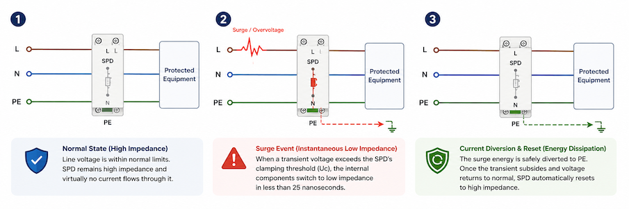
Diagrama que muestra cómo funciona un dispositivo de protección contra sobretensiones en tres etapas: operación normal de alta impedancia, respuesta a la sobretensión y desviación de corriente a tierra seguida de reinicio automático.
El proceso de trabajo en 3 pasos
Estado normal (alta impedancia): Cuando la tensión de línea se mantiene dentro de los límites operativos normales, los componentes internos mantienen una impedancia de varios megaohmios. El SPD permanece “invisible” para el circuito y prácticamente no consume corriente de fuga.
Evento de sobretensión (baja impedancia instantánea): En el momento en que una tensión transitoria supera el umbral de limitación (Uc) del SPD, los elementos internos no lineales conmutan de alta resistencia a baja resistencia en menos de 25 nanosegundos.
Derivación de corriente y restablecimiento (disipación de energía): La energía de la sobretensión se canaliza de forma segura a través del conductor de puesta a tierra (PE). Una vez que el pico transitorio disminuye y la tensión de línea vuelve a la normalidad, los componentes internos se recuperan automáticamente a su estado de alta impedancia, restableciendo el funcionamiento normal del circuito.
Los componentes internos principales: MOV frente a GDT
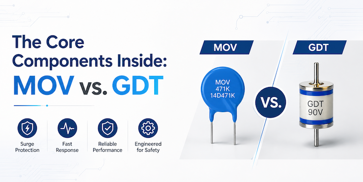
Comparación entre MOV y GDT, los dos componentes de protección contra sobretensiones más comunes usados en SPDs.
El mecanismo de funcionamiento se basa en componentes eléctricos no lineales de alto rendimiento integrados dentro del módulo:
Varistores de Óxido Metálico (MOV): El componente más utilizado en SPDs Tipo 2 para AC y DC. Los MOV presentan una caída brusca en la resistencia eléctrica a medida que aumenta la tensión, ofreciendo capacidades excepcionales de absorción de energía y tiempos de respuesta en subnanosegundos.
Tubos de descarga de gas (GDT): Se emplean habitualmente en arquitecturas de explosor de Tipo 1 o en la protección de líneas de comunicación. Los GDT provocan un arco eléctrico e ionizan el gas cuando se activan, capaces de descargar corrientes de rayo elevadas sin destrucción térmica.
¿Cuáles son los principales tipos de dispositivos de protección contra sobretensiones?
Un evento repentino de rayo o la conmutación y el arranque de equipos de alta potencia en una instalación industrial pueden generar una sobretensión transitoria de gran magnitud en un período muy corto. Dichas sobretensiones pueden dañar controladores costosos, servidores, variadores de frecuencia y otros equipos electrónicos sensibles. En casos graves, pueden incluso provocar la parada de toda una línea de producción. Sin embargo, no todos los dispositivos de protección contra sobretensiones están diseñados para soportar corrientes de rayo de alta energía, y no todos los tipos de SPD son adecuados para instalarse en el mismo punto del sistema de distribución eléctrica.
Un dispositivo de protección contra sobretensiones puede entenderse como el “airbag” del sistema eléctrico, pero cada tipo de SPD tiene una función de protección claramente definida. Desde la primera línea de defensa en la entrada de servicio del edificio, donde se derivan las corrientes de sobretensión de alta energía, hasta la protección intermedia en los cuadros de distribución y la protección fina cerca de los equipos sensibles, SPDs Tipo 1, Tipo 2 y Tipo 3operan en diferentes niveles del sistema de protección. Además, SPDs combinados Tipo 1+2 integran la capacidad de descarga de corriente de rayo de un dispositivo de Tipo 1 con el rendimiento de limitación de tensión de un dispositivo de Tipo 2 en una sola unidad, lo que los convierte en una solución práctica para entradas de servicio y cuadros de distribución principales. Una protección eficaz contra sobretensiones depende de la selección y coordinación de estos dispositivos según el riesgo del sistema, la ubicación de la instalación y la capacidad de soportar impulsos del equipo protegido.
Dispositivo de protección contra sobretensiones de Tipo 1
Los SPDs Tipo 1 son dispositivos primarios de protección contra sobretensiones instalados en el lado de línea de la entrada principal del servicio (entre el secundario del transformador de la compañía eléctrica y el interruptor principal de servicio).
Función principal: Diseñados para soportar transitorios de alta energía causados por impactos directos o cercanos de rayos y por conmutaciones de la red eléctrica antes de que la sobretensión llegue al cuadro de distribución principal.
Norma de prueba y forma de onda: Evaluado según las normas IEC 61643 utilizando la forma de onda de corriente de impulso de 10/350 μs (Iimp), que simula descargas de energía de pico alto.
Dispositivo de protección contra sobretensiones Tipo 2
Los DPS Tipo 2 sirven como protección secundaria y se instalan en el lado de carga del interruptor principal de servicio, normalmente ubicados dentro de tableros de subdistribución o paneles de control de derivaciones.
Función principal: Limita las tensiones de impulso residuales que pasan a través de los DPS Tipo 1 y mitiga las sobretensiones generadas internamente por cargas de conmutación inductivas (p. ej., unidades HVAC, motores y variadores de frecuencia).
Norma de prueba y forma de onda: Probado utilizando la forma de onda de corriente de 8/20 μs, caracterizada por la corriente nominal de descarga (In) y la corriente máxima de descarga (Imax).
Dispositivo de protección contra sobretensiones Tipo 3
Los DPS Tipo 3 proporcionan protección localizada en el punto de uso para equipos terminales altamente sensibles.
Función principal: Filtra las sobretensiones transitorias residuales de bajo nivel directamente en el terminal de carga para evitar la ruptura del aislamiento o la corrupción de datos en microelectrónica.
Requisito de instalación: Debe instalarse aguas abajo con una distancia mínima de conductor (normalmente al menos 10 metros / 30 pies) desde el SPD Tipo 2 aguas arriba para asegurar un desacoplamiento y coordinación energética adecuados.
Dispositivo de protección contra sobretensiones Tipo 1+2 (Tipo combinado)
Los DPS Tipo 1+2 (también clasificados como Clase I+II) combinan la capacidad de descarga de corriente de impulso de alta energía de un dispositivo Tipo 1 con el bajo nivel de protección de tensión (Up) de un dispositivo Tipo 2 en una sola unidad compacta.
Función principal: Desvía directamente corrientes de rayo directo de alta energía mientras limita simultáneamente transitorios de conmutación de bajo nivel, proporcionando protección continua sin requerir una distancia mínima de desacoplamiento entre unidades separadas Tipo 1 y Tipo 2.
Norma de prueba y forma de onda: Probado doblemente según las normas IEC 61643 tanto para corrientes de impulso de 10/350 μs (Iimp) como para corrientes de descarga nominales/máximas de 8/20 μs (In / Imax).
Nota de ingeniería: La protección eficaz contra sobretensiones depende de una protección coordinada en diferentes niveles. Los DPS Tipo 1 o Tipo 1+2 manejan sobretensiones de alta energía en la entrada del sistema, los DPS Tipo 2 protegen los circuitos de distribución y los DPS Tipo 3 proporcionan una protección fina para equipos sensibles.
SPDs Tipo 1, Tipo 2, Tipo 3 y Tipo 1+2: Diferencias clave
Característica
SPD Tipo 1
SPD Tipo 1+2
SPD Tipo 2
SPD Tipo 3
Función principal
Desvía la corriente de rayo directo
Combina la descarga de corriente de rayo y la protección contra sobretensiones
Protege contra rayos inducidos y sobretensiones de conmutación
Protección final para equipos sensibles
Ubicación de instalación
Entrada de servicio
Entrada de servicio o tablero de distribución principal
Tablero de distribución principal o secundario
Cerca del equipo protegido
Forma de onda de prueba
10/350 μs
10/350 μs y 8/20 μs
8/20 μs
Onda combinada
Parámetros principales
Iimp, Up
Iimp, In, Imax, Up
In, Imax, Up
Uoc, Up
Etapa de protección
Protección primaria
Protección primaria y secundaria
Protección secundaria
Protección final
La tabla anterior ofrece una comparación rápida de los cuatro tipos principales de SPD. En la práctica, la selección del dispositivo de protección contra sobretensiones adecuado depende de la ubicación de la instalación, el riesgo de exposición a rayos, la configuración del sistema y el nivel de protección requerido. En muchas instalaciones, se coordinan múltiples tipos de SPD para lograr una protección eficaz contra sobretensiones en todo el sistema eléctrico.
Cómo seleccionar el dispositivo de protección contra sobretensiones (SPD) adecuado
Elegir el dispositivo de protección contra sobretensiones (SPD) adecuado implica algo más que seleccionar la corriente de descarga nominal más alta. La tensión del sistema, la ubicación de la instalación, la exposición a rayos, la disposición de la puesta a tierra y la coordinación entre las etapas de protección desempeñan un papel fundamental en el rendimiento general de la protección contra sobretensiones. El siguiente ejemplo ilustra por qué la selección adecuada del SPD es esencial.
A finales de 2023, una fuerte tormenta eléctrica azotó una instalación de fabricación industrial en el centro de Texas. Un rayo directo golpeó la línea de servicio público a menos de 200 metros del patio principal de distribución de energía de la instalación. La planta tenía instalado un supresor de sobretensiones básico en el tablero principal de baja tensión, lo que llevó a la gerencia de la planta a creer que sus operaciones estaban completamente protegidas.
En cuestión de milisegundos, la realidad de una protección contra sobretensiones incompleta se hizo evidente:
Pérdida financiera masiva: El impulso inicial de alta energía sobrepasó el único protector del panel, enviando una severa sobretensión transitoria a través de la red de distribución interna.
Daños catastróficos en los equipos: Más de 15 variadores de frecuencia (VFD), docenas de controladores lógicos programables (PLC), conjuntos de sensores sensibles y centros de mecanizado CNC computarizados sufrieron una ruptura inmediata del aislamiento y fallos en las placas de circuitos.
Costoso tiempo de inactividad no planificado: Toda la línea de producción automatizada quedó fuera de servicio durante 16 días mientras se adquirían y reingenierizaban los componentes de reemplazo, lo que resultó en más de $1,2 millones en costos directos de reemplazo de hardware y pérdida de productividad operativa.
Un análisis de ingeniería forense realizado tras el incidente reveló la causa raíz: la falta de protección contra sobretensiones en cascada y de múltiples etapas. La instalación dependía de un único dispositivo de protección en la entrada principal, esperando que absorbiera corrientes de rayo de alta energía y, al mismo tiempo, limitara los picos de tensión de bajo nivel para los microelectrónicos sensibles aguas abajo, una tarea que ningún dispositivo individual está diseñado para realizar por sí solo.
Las sobretensiones transitorias, ya sean generadas externamente por rayos directos o indirectos, o internamente por la conmutación de cargas inductivas pesadas, siguen trayectorias físicas predecibles. Proteger una infraestructura industrial, comercial o residencial requiere una arquitectura de protección escalonada y por niveles definida por normas internacionales reconocidas como IEC 61643-01 y los UL 1449.
Para seleccionar el SPD adecuado, se deben considerar varios factores clave, incluyendo el sistema eléctrico, la tensión de operación, el tipo de SPD, el nivel de protección y los requisitos de instalación.
Selección de SPD de un vistazo
Paso 1: Confirmar el sistema de alimentación y seleccionar Uc
Paso 2: Seleccionar el tipo de SPD según la ubicación de instalación y la zona de protección contra rayos (LPZ)
Paso 3: Determinar Iimp, In e Imax
Paso 4: Verificar el nivel de protección de tensión Up
Paso 5: Confirmar el número de polos, el dispositivo de desconexión, la señalización remota y la protección de respaldo
Paso 6: Verificar la coordinación de energía entre múltiples DPS
Las siguientes secciones explican cada paso con más detalle y muestran cómo estos factores afectan la selección del SPD.
Paso 1: Confirmar el sistema de alimentación y seleccionar Uc
Sistema de alimentación
Selección típica de Uc
Nota de selección
Sistema TN-S, TN-C-S o TT de 230/400 V
275 V AC para protección L–N
Selección común para sistemas de distribución estándar de 230 V AC
Sistema IT de 400 V
Seleccionar según la tensión más alta posible entre línea y tierra
La tensión a tierra puede aumentar durante la primera falla de aislamiento
Sistema Solar Fotovoltaico DC
Ucpv debe ser superior a la tensión máxima de circuito abierto del campo fotovoltaico
Considerar el aumento de Voc a baja temperatura y la tensión del sistema, como 600 V, 1000 V o 1500 V DC
Paso 2: Seleccionar el tipo de SPD según la ubicación de instalación y la zona de protección contra rayos (LPZ)
Los tipos de SPD deben seleccionarse según la ubicación de instalación, la zona de protección contra rayos, el riesgo de corriente de rayo y la capacidad de soportar impulsos del equipo aguas abajo. Las categorías comunes de SPD para sistemas de baja tensión incluyen SPD Tipo 1, Tipo 2, Tipo 3 y combinados Tipo 1+2.
SPD Tipo 1 – Protección contra corriente de rayo
Ubicación de instalación: Entrada de servicio del edificio, tablero principal de baja tensión y el límite entre LPZ 0 y LPZ 1.
Función principal: Descarga corrientes de rayo de alta energía que pueden ingresar a la instalación eléctrica a través del suministro de energía entrante.
Parámetros clave: Probado con una forma de onda de 10/350 μs. Las clasificaciones comunes de Iimp incluyen 12,5 kA, 25 kA y valores superiores. El nivel de protección de tensión, Up, suele estar alrededor de 2,5 kV, dependiendo del diseño del producto.
Aplicaciones típicas: Plantas industriales, instalaciones al aire libre, edificios grandes e instalaciones con sistemas externos de protección contra rayos o un alto riesgo de corrientes de rayo directas.
Un SPD Tipo 1 está diseñado principalmente para manejar energía de corriente de rayo alta. Puede ser necesario protección adicional Tipo 2 o Tipo 3 aguas abajo para reducir el voltaje residual que llega a equipos sensibles.
SPD Tipo 2 – Protección contra sobretensiones a nivel de distribución
Ubicación de instalación: Tableros de distribución principales, tableros de subdistribución, paneles de energía de talleres y gabinetes de control industrial.
Función principal: Protege contra sobretensiones inducidas por rayos, transitorios de conmutación y energía de sobretensión residual que pasa a través de un SPD Tipo 1 aguas arriba.
Parámetros clave: Probado con una forma de onda de 8/20 μs. Las clasificaciones comunes incluyen corriente nominal (In) de 20 kA y corriente máxima (Imax) de 40–80 kA. El nivel de protección de tensión, Up, suele estar entre 1,5 y 1,8 kV.
Aplicaciones típicas: Edificios residenciales, instalaciones comerciales y sistemas generales de distribución de energía industrial.
Los SPD Tipo 2 protegen los sistemas eléctricos contra sobretensiones inducidas por rayos, transitorios de conmutación y energía de sobretensión residual que pasa a través de un SPD Tipo 1 aguas arriba.
SPD Tipo 3 – Protección final para equipos sensibles
Ubicación de instalación: Cerca de PLC, variadores de frecuencia, servidores, instrumentos, tomacorrientes y otros equipos terminales sensibles.
Función principal: Limita aún más la sobretensión residual y proporciona protección de etapa final para equipos electrónicos sensibles.
Parámetros clave: Probado con una onda combinada. Los parámetros principales son Uoc y Up, aunque algunos productos también pueden especificar una corriente de descarga nominal.
Aplicaciones típicas: Sistemas de automatización, equipos de comunicación, servidores, instrumentos de medición y otras cargas electrónicas sensibles.
Los SPD Tipo 3 tienen capacidad limitada de manejo de energía y normalmente deben coordinarse con un SPD Tipo 1, Tipo 2 o Tipo 1+2 aguas arriba.
SPD Combinado Tipo 1+2 – Protección contra corriente de rayo y sobretensiones
Ubicación de instalación: Entradas de servicio de edificios, cuadros generales, paneles de distribución AC para sistemas solares fotovoltaicos, cuadros de distribución compactos e instalaciones de retrofit.
Función principal: Combina la capacidad de descarga de corriente de rayo y la limitación de sobretensión en un solo dispositivo.
Parámetros clave: Deben considerarse Iimp, In, Imax y Up. Las clasificaciones comunes de Iimp incluyen 12,5 kA y 25 kA por polo, mientras que In suele ser 20 kA o superior. Los valores finales deben confirmarse según las especificaciones del producto y los requisitos del proyecto.
Aplicaciones típicas: Instalaciones industriales, edificios comerciales, sistemas solares fotovoltaicos, cuadros compactos y proyectos con espacio de instalación limitado.
Un SPD Tipo 1+2 cumple con los requisitos de protección Tipo 1 y Tipo 2 en un solo dispositivo. Combina la capacidad de descarga de corriente de rayo de alta energía con protección de limitación de voltaje.
Guía de selección de SPD por aplicación
Condición de aplicación
Tipo de SPD recomendado
Ubicación de instalación típica
Parámetros clave
Edificio con sistema externo de protección contra rayos
Tipo 1 o Tipo 1+2
Entrada de servicio o tablero principal
Iimp, Up
Sistema de distribución general residencial o comercial
Tipo 2
Tablero de distribución principal o secundario
In, Imax, Up
Equipos electrónicos sensibles
Tipo 3
Cerca del equipo protegido
Uoc, Up
Instalación industrial con alta exposición a rayos
Tipo 1+2 con protección Tipo 2 aguas abajo
Tablero principal y tableros de subdistribución
Iimp, In, Up
Sistema solar fotovoltaico DC
Tipo DC 1+2 o Tipo DC 2
Caja combinadora PV o cuadro de distribución DC
Ucpv, Iimp o In, Up
Cargas sensibles ubicadas lejos del tablero de distribución principal
Tipo 2 o Tipo 3 adicional
Cerca del equipo aguas abajo
Up, coordinación
Paso 3: Determinar Iimp, In e Imax
La corriente nominal de descarga de un SPD debe seleccionarse de acuerdo con la energía de sobretensión esperada, la ubicación de instalación, la exposición a rayos y el tipo de SPD. Los tres parámetros principales de corriente son Iimp, In e Imax.
Iimp – Corriente de descarga de impulso
Iimp representa la corriente de impulso de rayo que un SPD de Tipo 1 o Tipo 1+2 puede descargar bajo una forma de onda de 10/350 μs. Se utiliza principalmente para evaluar la capacidad del SPD de soportar corrientes de rayo de alta energía en la entrada de servicio o en el límite LPZ 0–LPZ 1.
Las clasificaciones comunes de In incluyen:
10 kA para protección de terminal de servicio ligero
20 kA para distribución residencial y comercial general
30–40 kA o superior para instalaciones industriales y de alta exposición
Para la mayoría de los tableros de distribución principales y secundarios, se selecciona comúnmente una clasificación de In de 20 kA o superior.
Imax – Corriente máxima de descarga
Imax representa la corriente de sobretensión máxima de 8/20 μs que un SPD puede descargar una vez o un número limitado de veces sin fallar. Imax normalmente es superior a In, pero no debe utilizarse como único criterio de selección porque no representa la capacidad de funcionamiento repetido del SPD.
Las clasificaciones típicas de Imax incluyen:
20–40 kA para sistemas de distribución generales
40–80 kA para instalaciones industriales
Valores superiores para entornos de sobretensión severos
Guía práctica de selección
Condición de instalación
Enfoque del parámetro recomendado
Entrada de servicio del edificio con sistema de protección contra rayos
Priorizar Iimp
Tablero de distribución principal o secundario
Priorizar In e Imax
Instalación industrial con alta exposición a rayos
Mayor Iimp e In
Equipos terminales sensibles
Un Up más bajo suele ser más importante que una clasificación de corriente muy alta
SPD Tipo 1+2
Verificar Iimp, In, Imax y Up conjuntamente
Nota de ingeniería Una clasificación de corriente de descarga más alta no significa automáticamente una mejor protección. La selección del SPD debe equilibrar la capacidad de descarga, el nivel de protección de tensión, la ubicación de instalación, la protección de respaldo y la coordinación de energía. Un SPD con un Imax muy alto pero un Up o Uc inadecuados aún puede no proporcionar una protección eficaz.
Paso 4: Verificar el nivel de protección de tensión Up
El nivel de protección de tensión, Up, indica la capacidad del SPD de limitar la tensión de sobretensión bajo condiciones de ensayo especificadas. Es un valor declarado proporcionado por el fabricante y representa el nivel de protección alcanzado cuando el SPD descarga la corriente de impulso especificada. Un Up más bajo generalmente significa que se permite que pase menos tensión de sobretensión hacia los equipos aguas abajo. Sin embargo, Up no debe evaluarse de forma aislada. Debe considerarse junto con la tensión del sistema, la tensión máxima de funcionamiento continuo Uc, la capacidad de corriente de descarga, la capacidad de soportar sobretensiones temporales y la tensión de resistencia a impulsos del equipo protegido.
Comparar Up con la tensión de resistencia a impulsos del equipo
El SPD seleccionado debe limitar la tensión de sobretensión a un nivel inferior a la tensión de resistencia a impulsos del equipo aguas abajo. Un principio práctico de selección es:
El nivel de protección efectivo en el equipo debe permanecer por debajo de la tensión de resistencia a impulsos nominal del equipo.
Debe permitirse un margen de seguridad suficiente porque la tensión real que llega al equipo puede ser superior al valor de Up indicado en la hoja de datos.
Considerar la longitud del cable de instalación
El valor de Up se mide en los terminales del SPD bajo condiciones de laboratorio especificadas. En una instalación real, la inductancia de los conductores de conexión puede añadir tensión adicional durante la descarga de sobretensión.
Por lo tanto:
Mantener los conductores de conexión lo más cortos y directos posible.
Evitar bucles innecesarios y curvas pronunciadas.
Colocar el SPD cerca del circuito protegido.
Instalar protección adicional aguas abajo cuando el equipo protegido esté lejos del SPD principal.
Los cables de conexión largos pueden reducir la eficacia incluso de un SPD con Up bajo. Por lo tanto, una instalación correcta es tan importante como la selección del producto. Phoenix Contact también señala que los conductores de conexión excesivamente largos pueden crear problemas de instalación y recomienda prestar atención a la longitud y el trazado del cable.
Enfoque práctico de selección
Posición de protección
Enfoque principal de selección
Entrada de servicio del edificio
Equilibrar Iimp y Up
Tablero de distribución principal o secundario
Verificar In, Imax y Up
Equipos electrónicos sensibles
Seleccione un Up suficientemente bajo e instale el SPD cerca de la carga
SPD combinado Tipo 1+2
Verifique Iimp, In y Up juntos
Larga distancia entre tableros de distribución
Considere un SPD adicional aguas abajo
Nota de ingeniería: No seleccione un SPD basándose únicamente en el valor de Up más bajo. Un SPD con un Up bajo pero capacidad de descarga insuficiente puede dañarse por la corriente de sobretensión esperada. Por el contrario, un SPD con alta capacidad de descarga pero un Up excesivamente alto puede no proteger adecuadamente los equipos sensibles. La selección final debe equilibrar: Uc + Up + Iimp/In/Imax + tensión soportada del equipo + distancia de instalación
Paso 5: Confirmar el número de polos, el dispositivo de desconexión, la señalización remota y la protección de respaldo
Después de seleccionar el tipo de SPD y las características eléctricas, confirme que el dispositivo coincida con la configuración del sistema y los requisitos de instalación. El número de polos, la función de desconexión interna, la opción de señalización remota y el dispositivo de protección de respaldo afectan la seguridad y confiabilidad de la instalación.
Confirme el Número de Polos
La configuración de polos del SPD debe coincidir con el sistema de alimentación, la disposición de conductores y el modo de protección.
Sistema de alimentación
Configuración Común del SPD
Sistema monofásico L–N
1P+N o 2P
Sistema trifásico de tres hilos
3P
Sistema trifásico de cuatro hilos
3P+N o 4P
Sistema TN-C
Protección entre conductores de fase y PEN
Sistema TN-S o TN-C-S
Protección entre L–N y N–PE, dependiendo del circuito seleccionado
Sistema TT
Comúnmente utiliza un circuito 3+1 o 1+1
Sistema DC o PV
Seleccione la configuración de polos según la tensión del sistema, la polaridad y la disposición de puesta a tierra
El número de polos por sí solo no es suficiente para determinar la idoneidad. El circuito de protección también debe coincidir con la disposición de puesta a tierra del sistema y la tensión que puede aparecer entre conductores.
Verifique el Dispositivo de Desconexión
La mayoría de los SPD incluyen un dispositivo interno de desconexión térmica que separa el componente protector del sistema eléctrico cuando alcanza el fin de su vida útil o se sobrecalienta. El dispositivo de desconexión ayuda a reducir el riesgo de:
Fuga térmica
Sobrecalentamiento
Cortocircuito
Incendio causado por un MOV fallido u otro componente de protección
El SPD también debe proporcionar un indicador de estado claro para que el personal de mantenimiento pueda identificar cuándo necesita reemplazarse el módulo de protección.
Determine si se Requiere Señalización Remota
Un contacto de señalización remota permite monitorear el estado operativo del SPD desde un panel de control, sistema de alarma, PLC o sistema de gestión de edificios.
La señalización remota es particularmente útil en:
Subestaciones no atendidas
Líneas de producción industrial
Centros de datos
Instalaciones de telecomunicaciones
Plantas solares fotovoltaicas
Sistemas de alimentación críticos
Cuando se requiere monitoreo remoto, verifique el tipo de contacto, la disposición de terminales, la tensión nominal y la corriente nominal del contacto de señalización.
Seleccione el Dispositivo de Protección de Respaldo
Un SPD puede requerir un fusible o disyuntor aguas arriba para proteger el circuito si el SPD falla o desarrolla un cortocircuito interno.
El dispositivo de protección de respaldo debe seleccionarse según:
El fusible o disyuntor de respaldo máximo especificado por el fabricante
La corriente de cortocircuito disponible en el punto de instalación
La clasificación de corriente de cortocircuito del SPD
El tipo y el área de sección transversal de los conductores de conexión
Coordinación con el dispositivo de protección aguas arriba
No seleccione el fusible de respaldo o el interruptor automático solo según la clasificación de corriente de descarga del SPD. Siga la tabla de coordinación y las instrucciones de instalación del fabricante.
Guía práctica de selección
Elemento de selección
Punto principal a confirmar
Número de polos
Coincidir los conductores de fase, el conductor neutro y el sistema de puesta a tierra
Dispositivo de desconexión
Confirmar la desconexión térmica interna y la indicación de estado visible
Señalización remota
Confirmar si se requiere alarma remota o monitoreo del sistema
Protección de respaldo
Siga la clasificación de fusible o interruptor automático recomendada por el fabricante
Módulo reemplazable
Verificar si el cartucho de protección se puede reemplazar sin cambiar la base
Clasificación de cortocircuito
Confirmar la idoneidad para la corriente de cortocircuito prospectiva
Nota de ingeniería Un SPD con el Uc, Up y la clasificación de corriente de descarga correctos puede seguir siendo inadecuado si la configuración de polos o la protección de respaldo es incorrecta. Siempre verifique el arreglo completo de la instalación en lugar de seleccionar el SPD solo por los parámetros de su etiqueta frontal.
Paso 6: Verificar la coordinación de energía entre múltiples DPS
Cuando se instalan varios SPDs a diferentes niveles del sistema eléctrico, deben operar en una secuencia coordinada. El SPD aguas arriba debe descargar la mayor energía de sobretensión, mientras que el SPD aguas abajo reduce aún más el voltaje residual antes de que llegue a equipos sensibles. La coordinación adecuada de energía evita que un SPD aguas abajo se sobrecargue antes de que el dispositivo aguas arriba haya desviado la corriente de sobretensión principal.
Disposición típica de protección en cascada
Nivel de protección
Tipo típico de SPD
Ubicación de instalación típica
Función principal
Primera etapa
Tipo 1 o Tipo 1+2
Entrada de servicio o tablero principal
Descargar corrientes de rayos de alta energía
Segunda etapa
Tipo 2
Tablero de subdistribución o armario de control
Limitar sobretensiones residuales y sobrevoltajes de conmutación
Etapa final
Tipo 3
Cerca de equipos sensibles
Reducir aún más el voltaje residual
Verificar la distancia entre SPDs
La longitud del cable entre dos SPDs afecta cómo se comparte la energía de sobretensión. La inductancia del cable de conexión puede ayudar a crear la diferencia de voltaje requerida para que los SPDs aguas arriba y aguas abajo operen en la secuencia correcta. Sin embargo, no existe una regla única de separación que se aplique a todas las combinaciones de SPD. La distancia requerida depende de:
Tecnología y diseño interno del SPD
Valores Up aguas arriba y aguas abajo
Clasificaciones de corriente de descarga
Enrutamiento del cable y longitud del conductor
Datos de coordinación probados por el fabricante
Algunas instalaciones utilizan la longitud del cable para proporcionar desacoplamiento natural. Cuando la distancia disponible es insuficiente, puede ser necesaria una combinación coordinada de SPD o un elemento de desacoplamiento especificado.
Utilizar combinaciones verificadas por el fabricante
El método más seguro es seleccionar SPDs aguas arriba y aguas abajo que hayan sido probados y confirmados como una combinación coordinada energéticamente por el fabricante. Verifique la documentación del fabricante para:
Combinaciones permitidas de SPD aguas arriba y aguas abajo
Distancia mínima de separación
Si se requiere un elemento de desacoplamiento adicional
Capacidad máxima de corriente de descarga
Requisitos del dispositivo de protección de respaldo
Nivel de protección de voltaje efectivo en la carga
No asuma que dos SPDs están coordinados simplemente porque uno es Tipo 1 y el otro es Tipo 2.
Considere la distancia al equipo protegido
Cuando el equipo sensible se encuentra lejos del SPD principal, puede ser necesario un SPD adicional aguas abajo. Los cables largos pueden captar nuevas sobretensiones inducidas y también pueden aumentar el voltaje que llega al equipo. Para circuitos de distribución largos, considere instalar:
Protección de Tipo 2 en los cuadros de distribución aguas abajo
Protección de Tipo 3 cerca del equipo terminal sensible
SPDs adicionales donde lo requiera el diseño del proyecto o las instrucciones del fabricante
Lista de verificación de coordinación práctica
Elemento a verificar
Requisito de selección
Secuencia de SPD
Tipo 1 o Tipo 1+2 en la parte superior, seguido de Tipo 2 y Tipo 3 donde sea necesario
Capacidad de energía
El SPD en la parte superior maneja la mayor energía de sobretensión
Limitación de voltaje
El SPD en la parte inferior proporciona un nivel de protección efectivo más bajo
Distancia de separación
Siga los requisitos probados por el fabricante
Diseño del cableado
Mantenga todas las conexiones de SPD cortas y directas
Compatibilidad del producto
Utilice combinaciones coordinadas verificadas siempre que sea posible
Distancia del equipo protegido
Agregue protección aguas abajo cuando la carga esté lejos del SPD principal
Nota de ingeniería La coordinación de energía no se logra simplemente instalando varios SPDs en serie. Los dispositivos deben compartir la energía de sobretensión correctamente sin sobrecargar la unidad aguas abajo. Un sistema mal coordinado puede hacer que el SPD de Tipo 2 o Tipo 3 funcione demasiado pronto y absorba más energía de la que puede soportar. Por lo tanto, la coordinación final debe seguir los datos de combinación probados por el fabricante y las instrucciones de instalación.
¿Dónde se utilizan comúnmente los dispositivos de protección contra sobretensiones?
Los dispositivos de protección contra sobretensiones se utilizan ampliamente en sistemas eléctricos residenciales, comerciales, industriales, de comunicación, de energía renovable, de transporte y exteriores. Su principal propósito es proteger equipos eléctricos y electrónicos de sobretensiones transitorias causadas por rayos, operaciones de conmutación y perturbaciones en el sistema de energía. El tipo de SPD requerido depende del voltaje del sistema, la ubicación de instalación, el arreglo de puesta a tierra, la sensibilidad del equipo y la exposición esperada a sobretensiones.
Aplicación
Equipos típicos protegidos
Enfoque de protección común
Edificios residenciales
Electrodomésticos, computadoras, sistemas de seguridad y dispositivos de hogar inteligente
Tipo 2 en el cuadro de distribución principal; Tipo 1 o Tipo 1+2 pueden ser necesarios para edificios con protección contra rayos externa
Edificios comerciales
Ascensores, sistemas HVAC, alarmas contra incendios, CCTV, servidores y sistemas de gestión de edificios
Tipo 1 o Tipo 1+2 en la entrada de servicio, seguido de protección Tipo 2 en los cuadros de distribución en la parte inferior
Instalaciones industriales
PLCs, variadores de frecuencia, sensores, equipos de automatización y líneas de producción
Protección coordinada de Tipo 1, Tipo 2 y Tipo 3
Centros de datos y sistemas de comunicación
Servidores, sistemas UPS, equipos de red, dispositivos de comunicación y líneas de señal
SPDs de línea de energía combinados con protección dedicada de datos y líneas de señal
Sistemas solares fotovoltaicos
Módulos PV, cajas combinadoras, inversores y circuitos de distribución AC/DC
SPDs DC en el lado PV y SPDs AC en la salida del inversor
Estaciones de carga de vehículos eléctricos
Cargadores AC, cargadores rápidos DC, controladores, módulos de pago y equipos de comunicación
Protección SPD en la alimentación entrante y en el equipo de carga
Protección de Tipo 2 en los cuadros de distribución aguas abajo.
Convertidores, inversores, sistemas de gestión de baterías, armarios de control y equipos de monitoreo
SPDs AC y DC seleccionados según la arquitectura del sistema
Equipos exteriores e iluminación LED
Farolas, sistemas de tráfico, cámaras, señales electrónicas y armarios de control exteriores
Protección local SPD cerca de equipos exteriores expuestos
En la práctica, los sistemas más grandes o complejos suelen requerir protección contra sobretensiones en varias etapas. Un SPD de alta energía puede instalarse en la entrada principal de servicio, mientras que SPDs adicionales Tipo 2 o Tipo 3 se instalan más cerca de los cuadros de distribución aguas abajo y equipos sensibles.
¿Dónde debe instalarse un dispositivo de protección contra sobretensiones?
La eficacia de un dispositivo de protección contra sobretensiones depende no solo de seleccionar el tipo correcto de SPD, sino también de instalarlo en la ubicación adecuada dentro del sistema eléctrico. Una instalación correcta ayuda a garantizar que la energía de la sobretensión se derive de forma segura a tierra antes de alcanzar equipos eléctricos o electrónicos sensibles. En la mayoría de las instalaciones de baja tensión, los SPDs se instalan en etapas para proporcionar protección coordinada desde la entrada de servicio hasta la carga final.
Ubicaciones típicas de instalación de SPD
Ubicación de instalación
Tipo de SPD recomendado
Propósito principal
Entrada de servicio
Tipo 1 o Tipo 1+2
Desviar corrientes de rayo de alta energía que entran en el edificio
Cuadro general de distribución
Tipo 2
Proteger los circuitos eléctricos aguas abajo de sobretensiones por conmutación y sobretensiones residuales de rayos
Cuadro de subdistribución
Tipo 2
Proporcionar protección adicional para circuitos derivados
Cerca de equipos sensibles
Tipo 3
Reducir la tensión residual de sobretensión antes de que alcance equipos electrónicos sensibles
Caja combinadora PV o cuadro de distribución DC
Tipo DC 1+2 o Tipo DC 2
Proteger circuitos DC fotovoltaicos e inversores
Armarios de control y sistemas de comunicación
SPDs de Tipo 2, Tipo 3 o para líneas de señal
Proteja PLCs, equipos de comunicación y electrónica de control
Recomendaciones de instalación
Para lograr el mejor rendimiento de protección, los SPDs deben instalarse lo más cerca posible del equipo o punto de distribución que protegen. Los conductores de conexión deben ser cortos y directos para minimizar la tensión inductiva adicional durante la descarga de sobretensión. Cuando la distancia entre el SPD principal y el equipo protegido es relativamente larga, puede ser necesario un SPD adicional aguas abajo para mantener un nivel de protección efectivo.
Al planificar una instalación de SPD, siempre se deben considerar los siguientes principios:
Instalar el tipo de SPD adecuado en cada nivel de protección.
Mantener todos los conductores de conexión lo más cortos y rectos posible.
Garantizar una conexión fiable al sistema de puesta a tierra.
Seguir las recomendaciones del fabricante para la protección de respaldo y la coordinación.
Utilizar protección coordinada en varias etapas para instalaciones eléctricas grandes o complejas.
Errores comunes en la instalación de SPDs
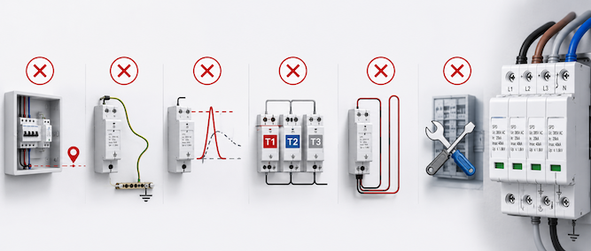
Incluso un dispositivo de protección contra sobretensiones correctamente seleccionado puede no proporcionar una protección efectiva si se instala incorrectamente. Los errores comunes de instalación pueden aumentar la tensión residual, reducir la vida útil del SPD o impedir que la corriente de sobretensión se derive de forma segura. Los siguientes aspectos deben verificarse durante la instalación y puesta en marcha.
Error común
Por qué es un problema
Práctica recomendada
Instalar un tipo de SPD incorrecto
Un SPD de Tipo 2 o Tipo 3 puede no ser capaz de soportar la energía de sobretensión esperada en la entrada de servicio
Ajustar el tipo de SPD a la ubicación de la instalación y la exposición a sobretensiones
Seleccionar un Uc incorrecto
Un valor de Uc demasiado bajo puede causar una operación prematura o daños; un valor demasiado alto puede reducir la eficacia de la protección
Seleccionar Uc según la tensión del sistema y el esquema de puesta a tierra
Uso de conductores de conexión excesivamente largos
Los conductores largos añaden tensión inductiva durante la descarga de sobretensión y aumentan el nivel efectivo de protección
Mantener el camino de conexión corto, directo y libre de bucles innecesarios
Puesta a tierra o unión equipotencial deficiente
Un camino a tierra de alta impedancia puede impedir que la corriente de sobretensión se descargue eficazmente
Garantizar una puesta a tierra y unión equipotencial fiables
Ignorar la protección de respaldo
Una falla interna del SPD puede no desconectarse de forma segura del sistema eléctrico
Instalar el fusible o interruptor automático especificado por el fabricante
Instalar solo un SPD en un sistema grande
Un único SPD puede no proporcionar protección suficiente para cuadros de distribución distantes o cargas sensibles
Utilizar protección coordinada en varias etapas cuando sea necesario
Uso incorrecto de un polo o configuración de circuito
El SPD puede no proteger todos los conductores requeridos o puede ser inadecuado para el sistema de puesta a tierra
Ajuste el circuito del SPD a la fase, neutro, polaridad y disposición de puesta a tierra
No coordinar múltiples SPDs
Un SPD aguas abajo puede absorber más energía de sobretensión de la que puede soportar
Utilice combinaciones coordinadas verificadas por el fabricante
Instalar el SPD demasiado lejos del equipo protegido
Los cables largos aguas abajo pueden permitir sobretensiones inducidas adicionales o aumentar el voltaje que llega al equipo
Agregue protección Tipo 2 o Tipo 3 aguas abajo cuando sea necesario
No inspeccionar o reemplazar un SPD defectuoso
Una vez que el SPD alcanza el fin de su vida útil, el circuito puede dejar de estar protegido
Verifique el indicador de estado y reemplace los módulos defectuosos de inmediato
Para evitar estos errores:
Seleccione el SPD según el voltaje del sistema, la disposición de puesta a tierra y el lugar de instalación.
Mantenga la trayectoria total de conexión lo más corta y directa posible.
Utilice el dispositivo de protección de respaldo correcto.
Asegure una puesta a tierra y una unión equipotencial confiables.
Verifique la coordinación entre los SPDs aguas arriba y aguas abajo.
Inspeccione el indicador de estado del SPD durante el mantenimiento rutinario.
Nota de ingeniería El SPD es solo una parte del sistema de protección contra sobretensiones. Su rendimiento real también depende del enrutamiento de conductores, calidad de la puesta a tierra, protección de respaldo, distancia de instalación y coordinación con otros SPDs. Un SPD de alto rendimiento puede proporcionar una protección deficiente si el diseño de la instalación es incorrecto.
Preguntas frecuentes sobre dispositivos de protección contra sobretensiones
¿Se puede usar un SPD sin fusible o interruptor automático de respaldo?
Depende del diseño del SPD y de los requisitos de instalación del fabricante. Algunos SPDs requieren un fusible o interruptor automático externo de respaldo, mientras que otros pueden incluir protección contra sobrecorriente integrada. El dispositivo de protección de respaldo se utiliza para desconectar el SPD de forma segura si desarrolla un cortocircuito interno o alcanza el fin de su vida útil. Su clasificación no debe seleccionarse solo según la corriente de descarga del SPD. Siga siempre la clasificación máxima especificada por el fabricante para el fusible o interruptor automático de respaldo, los requisitos de corriente de cortocircuito y las instrucciones de coordinación.
¿Cómo se debe mantener un dispositivo de protección contra sobretensiones?
El mantenimiento del SPD consiste principalmente en inspecciones regulares más que en reparaciones internas. Durante el mantenimiento eléctrico rutinario, revise el indicador de estado, el contacto de señalización remota, la tensión de los terminales, signos de sobrecalentamiento y el estado del dispositivo de protección de respaldo. El SPD también debe inspeccionarse después de tormentas severas, eventos de rayos, fallos importantes en el sistema eléctrico o disparos repetidos del dispositivo de protección aguas arriba. Reemplace el SPD o el módulo de protección enchufable si:
El indicador de estado muestra fallo.
Se activa una alarma remota.
La carcasa está decolorada, agrietada o sobrecalentada.
El fusible o interruptor automático de respaldo ha actuado debido a una falla del SPD.
Se han alcanzado los criterios de reemplazo del fabricante.
¿Cuánto dura un dispositivo de protección contra sobretensiones?
Un SPD no tiene una vida útil fija. Su duración depende del número, magnitud y duración de las sobretensiones que absorbe, así como del voltaje del sistema, sobretensiones temporales, condiciones ambientales y calidad del producto. Un SPD puede permanecer operativo durante muchos años en un entorno con pocas sobretensiones, pero una única sobretensión severa puede reducir significativamente su capacidad restante o causar una falla inmediata. Por lo tanto, se debe utilizar el indicador de estado y el contacto de señalización remota para determinar si el SPD sigue operativo. El reemplazo debe basarse en la condición real y las indicaciones del fabricante, no solo en un número fijo de años.
¿Necesito protección contra sobretensiones tanto para AC como para DC?
Puede ser necesario contar con protección contra sobretensiones tanto para AC como para DC cuando un sistema contiene circuitos separados de AC y DC. Un SPD para AC no puede reemplazar automáticamente a un SPD para DC porque ambos dispositivos están diseñados para diferentes características de voltaje, requisitos de extinción de arco y configuraciones del sistema. Por ejemplo, un sistema solar PV puede requerir:
Un SPD para DC en el arreglo PV, caja combinadora o entrada DC del inversor.
Un SPD para AC en la salida del inversor o en el cuadro de distribución AC.
Los sistemas de almacenamiento de energía, sistemas de carga de vehículos eléctricos y circuitos de control industrial en DC también pueden requerir protección separada para AC y DC. El SPD seleccionado debe estar clasificado para el voltaje real del sistema, polaridad, esquema de puesta a tierra y voltaje máximo de operación continua.
¿Puede un SPD dañado seguir protegiendo el equipo?
No se debe asumir que un SPD dañado proporciona protección efectiva. Algunos SPDs contienen un dispositivo interno de desconexión que aísla el componente de protección fallido mientras permite que el circuito eléctrico permanezca energizado. En esta condición, el equipo conectado puede continuar operando, pero la protección contra sobretensiones puede estar parcial o completamente perdida. Si el indicador de estado muestra fallo o se activa la alarma remota, reemplace el SPD o módulo de protección lo antes posible. Continuar operando sin reemplazo puede dejar el equipo aguas abajo sin protección.
¿Son obligatorios los SPDs para sistemas solares PV?
Los requisitos de SPD para sistemas solares PV dependen de la norma eléctrica aplicable, diseño de protección contra rayos, riesgo de instalación, trazado de cables y regulaciones locales. Los sistemas PV están particularmente expuestos a sobretensiones inducidas porque los módulos y cables DC suelen instalarse en exteriores y pueden cubrir una gran área. Los SPDs se instalan comúnmente en el lado DC, lado AC o en ambos. Ubicaciones típicas incluyen:
Cajas combinadoras PV
Entradas DC del inversor
Salidas AC del inversor
Cuadros principales de distribución AC
El tipo de SPD requerido depende de si el edificio cuenta con un sistema externo de protección contra rayos, la distancia de separación, la tensión del sistema y el nivel de exposición a rayos. Por lo tanto, los SPDs no se seleccionan simplemente porque el sistema sea fotovoltaico. La necesidad, tipo y posición de instalación deben determinarse según los requisitos aplicables del proyecto y la evaluación de riesgos.
¿BUSCA UN SPD ADECUADO PARA SU PROYECTO?
Después de comprender los diferentes tipos de SPD, parámetros de selección, ubicaciones de instalación y requisitos de coordinación, también puede explorar nuestra gama completa de dispositivos de protección contra sobretensiones para aplicaciones AC y DC. Visite nuestra categoría de productos de Dispositivos de Protección contra Sobretensiones (SPD) para comparar modelos disponibles, niveles de tensión, niveles de corriente de descarga, configuraciones de polos y opciones de aplicación.
SOBRE ESTA GUÍA
Esta guía fue preparada para ayudar a ingenieros, fabricantes de cuadros, contratistas eléctricos, integradores de sistemas y compradores industriales a comprender mejor los dispositivos de protección contra sobretensiones (SPDs), sus principios de funcionamiento, criterios de selección, prácticas de instalación y aplicaciones comunes.
Ingeniero Eléctrico | Distribución de Energía en Baja Tensión
Hola, soy Evan.
Soy ingeniero eléctrico con 10 años de experiencia en equipos eléctricos de baja tensión, protección de circuitos y sistemas de distribución de energía. Me especializo en selección de productos, ingeniería de aplicación y soporte técnico para proyectos industriales, comerciales y de energías renovables.
Para consultas técnicas, por favor contácteme en evan@jutrion.com.