A Surge Protective Device (SPD) is an electrical protection device designed to limit transient overvoltages and divert surge currents. Under normal operating conditions, the SPD remains in a high-impedance state and has little to no effect on the electrical system. When lightning, utility switching, motor starting and stopping, or other transient events cause a sudden rise in line voltage, the SPD rapidly switches to a low-impedance conductive state. This provides a discharge path for the surge current while limiting the residual voltage reaching downstream equipment, thereby reducing the risk of insulation breakdown, electronic component damage, equipment failure, and unplanned downtime.
The design, performance testing, and practical application of SPDs must comply with relevant standards. IEC 61643-11 specifies the performance requirements and test methods for surge protective devices connected to low-voltage AC power systems, while Article 242 of NFPA 70, the National Electrical Code (NEC), addresses the application of surge protection in electrical installations in the United States. These standards provide important guidance for the testing, selection, and installation of SPDs, helping improve the safety and reliability of modern low-voltage power distribution systems.
What Is an Electrical Surge?
An electrical surge is a short-duration spike in voltage or current that travels through a power, control, or communication circuit. It typically rises very quickly and then decays over a longer period. Although the event may last only a few microseconds, the resulting voltage can be high enough to damage insulation, electronic components, control equipment, and other sensitive loads. IEC 60050-161 defines a surge as a transient wave that propagates along a line or circuit and is characterized by a rapid rise followed by a slower decay.
What Causes Electrical Surges?
Electrical surges are commonly associated with two major sources: lightning-related events and switching operations within the power system. Lightning can introduce transient overvoltages through direct strikes, nearby strikes, or induced voltages in connected conductors. Switching surges may occur when motors, transformers, capacitor banks, contactors, relays, or other high-power loads are energized or disconnected. IEC 61000-4-5provides standardized methods for testing the immunity of electrical and electronic equipment against unidirectional surges caused by lightning effects and power-system switching transients.
COMPARISON OF LIGHTNING SURGES AND SWITCHING SURGES
Parameter
Lightning Surge
Switching Surge
Typical Waveforms
10/350 μs for direct lightning current; 8/20 μs for induced surge current; 10/700 μs for communication lines
1.2/50 μs voltage wave and 8/20 μs current wave
Occurrence Frequency
Relatively infrequent and mainly associated with thunderstorms
More frequent and may occur whenever electrical equipment is switched on or off
Energy Level
Very high energy, potentially reaching hundreds of kilojoules and causing immediate equipment damage
Generally lower energy, but repeated exposure can gradually degrade components
Recommended Protection Approach
Type 1 SPD at the main service entrance, followed by coordinated downstream surge protection
Type 2 or Type 3 SPD installed at distribution boards or close to sensitive equipment
Typical Overvoltage Range
From several kilovolts to tens of kilovolts
From several hundred volts to several kilovolts
Common Sources
Direct lightning strikes, nearby strikes, ground-potential rise, and induced lightning effects
Motors, transformers, capacitor banks, contactors, relays, and other switching devices
Typical Impact
Insulation breakdown, flashover, cable damage, fire, or immediate equipment failure
Electronic component degradation, control-system malfunction, data errors, or reduced equipment life
How does a surge protective device work?
A Surge Protective Device (SPD) works like an automated, ultra-fast electrical pressure relief valve.
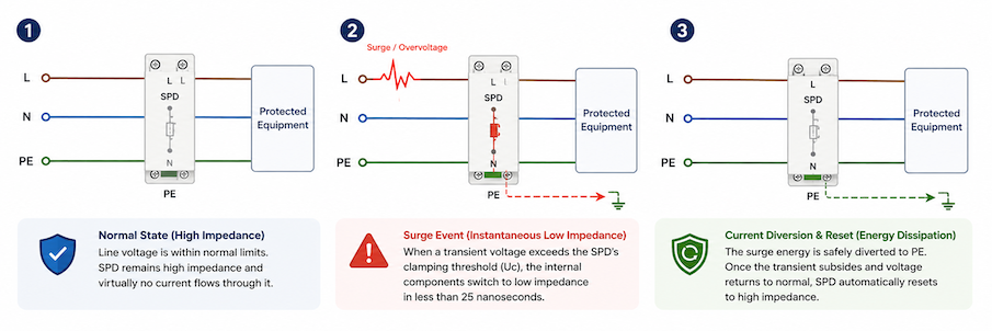
Under normal grid conditions, the SPD acts as an open switch with extremely high internal resistance (impedance), preventing any power from flowing through it. However, when an overvoltage spike (caused by lightning or grid switching) enters the system, the SPD instantly reacts within nanoseconds, dropping its resistance to near-zero. This creates a safe parallel path that diverts the massive surge current away from sensitive equipment and directly into the ground.
Diagram showing how a surge protective device works in three stages: normal high-impedance operation, surge response, and current diversion to earth followed by automatic reset.
The 3-Step Working Process
Normal State (High Impedance): When line voltage remains within normal operational limits, internal components maintain an impedance of several megohms. The SPD remains “invisible” to the circuit and draws virtually no leakage current.
Surge Event (Instantaneous Low Impedance): The moment a transient voltage exceeds the SPD’s clamping threshold (Uc), the non-linear internal elements switch from high resistance to low resistance in less than 25 nanoseconds.
Current Diversion & Reset (Energy Dissipation): The surge energy is safely channeled through the grounding conductor (PE). Once the transient spike subsides and the line voltage returns to normal, the internal components automatically recover to their high-impedance state, restoring standard circuit operations.
The Core Components Inside: MOV vs. GDT
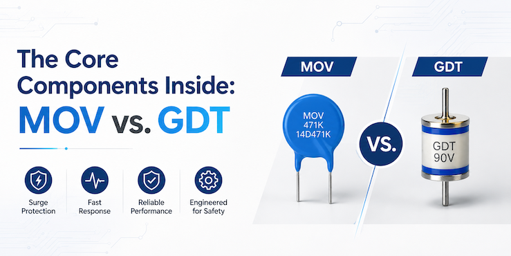
Comparison of MOV and GDT, the two most common surge protection components used in SPDs.
The working mechanism relies on high-performance non-linear electrical components built inside the module:
Metal Oxide Varistors (MOV): The most widely used component in Type 2 AC and DC SPDs. MOVs exhibit a sharp drop in electrical resistance as voltage increases, offering exceptional energy absorption capacities and sub-nanosecond response times.
Gas Discharge Tubes (GDT): Commonly deployed in Type 1 spark-gap architectures or communication line protection. GDTs spark over and ionize gas when triggered, capable of discharging high lightning currents without thermal destruction.
What Are the Main Types of Surge Protective Devices?
A sudden lightning event or the switching and startup of high-power equipment in an industrial facility can generate a high-magnitude transient overvoltage within a very short period. Such surges may damage expensive controllers, servers, variable frequency drives, and other sensitive electronic equipment. In severe cases, they can even cause an entire production line to shut down. However, not every surge protective device is designed to withstand high-energy lightning currents, and not every type of SPD is suitable for installation at the same point in the electrical distribution system.
A surge protective device can be understood as the electrical system’s “airbag,” but each SPD type has a clearly defined protective role. From the first line of defense at the building’s service entrance, where high-energy surge currents are diverted, to intermediate protection in distribution panels and fine protection near sensitive equipment, Type 1, Type 2, and Type 3 SPDsoperate at different levels of the protection system. In addition, Type 1+2 combined SPDs integrate the lightning-current discharge capability of a Type 1 device with the voltage-limiting performance of a Type 2 device in a single unit, making them a practical solution for service entrances and main distribution boards. Effective surge protection depends on selecting and coordinating these devices according to the system risk, installation location, and impulse withstand capability of the protected equipment.
Type 1 Surge Protective Device
Type 1 SPDs are primary surge protection devices installed on the line side of the main service entrance (between the secondary of the utility transformer and the main service disconnect).
Primary Function: Designed to withstand high-energy transients caused by direct or nearby lightning strikes and utility grid switching before the surge reaches the main distribution panel.
Test Standard & Waveform: Evaluated under IEC 61643 standards using the 10/350 μs impulse current waveform (Iimp), which simulates high-peak energy discharges.
Type 2 Surge Protective Device
Type 2 SPDs serve as secondary protection and are installed on the load side of the main service disconnect, typically located within sub-distribution boards or branch control panels.
Primary Function: Clamps residual impulse voltages that pass through Type 1 SPDs and mitigates internally generated surges caused by inductive switching loads (e.g., HVAC units, motors, and variable frequency drives).
Test Standard & Waveform: Tested using the 8/20 μs current waveform, characterized by nominal discharge current (In) and maximum discharge current (Imax).
Type 3 Surge Protective Device
Type 3 SPDs provide localized point-of-use protection for highly sensitive terminal equipment.
Primary Function: Filters residual low-level transient overvoltages right at the load terminal to prevent insulation breakdown or data corruption in microelectronics.
Installation Requirement: Must be installed downstream with a minimum conductor distance (typically at least 10 meters / 30 feet) from the upstream Type 2 SPD to ensure proper decoupling and energy coordination.
Type 1+2 Surge Protective Device (Combined Type)
Type 1+2 SPDs (also classified as Class I+II) combine the high-energy impulse discharge capacity of a Type 1 device with the low voltage protection level (Up) of a Type 2 device into a single compact unit.
Primary Function: Directly diverts high-energy direct lightning currents while simultaneously clamping low-level switching transients, providing seamless protection without requiring minimum decoupling distance between separate Type 1 and Type 2 units.
Test Standard & Waveform: Dual-tested under IEC 61643 standards for both 10/350 μs impulse currents (Iimp) and 8/20 μs nominal/maximum discharge currents (In / Imax).
Engineering Note: Effective surge protection relies on coordinated protection at different levels. Type 1 or Type 1+2 SPDs handle high-energy surges at the system entrance, Type 2 SPDs protect distribution circuits, and Type 3 SPDs provide fine protection for sensitive equipment.
Type 1, Type 2, Type 3, and Type 1+2 SPD: Key Differences
Feature
Type 1 SPD
Type 1+2 SPD
Type 2 SPD
Type 3 SPD
Main Function
Diverts direct lightning current
Combines lightning current discharge and surge protection
Protects against induced lightning and switching surges
Final protection for sensitive equipment
Installation Location
Service entrance
Service entrance or main distribution board
Main or sub-distribution board
Close to the protected equipment
Test Waveform
10/350 μs
10/350 μs and 8/20 μs
8/20 μs
Combination wave
Main Parameters
Iimp, Up
Iimp, In, Imax, Up
In, Imax, Up
Uoc, Up
Protection Stage
Primary protection
Primary and secondary protection
Secondary protection
Final protection
The table above provides a quick comparison of the four main SPD types. In practice, selecting the right surge protective device depends on the installation location, lightning exposure risk, system configuration, and the required level of protection. In many installations, multiple SPD types are coordinated to achieve effective surge protection throughout the electrical system.
How to Select the Right Surge Protective Device (SPD)
Choosing the right Surge Protective Device (SPD) involves more than simply selecting the highest discharge current rating. The system voltage, installation location, lightning exposure, grounding arrangement, and coordination between protection stages all play a critical role in determining overall surge protection performance. The following example illustrates why proper SPD selection is essential.
In late 2023, a severe thunderstorm swept through an industrial manufacturing facility in central Texas. A direct lightning strike struck the utility line less than 200 meters from the facility’s main power distribution yard. The plant did have a basic surge suppressor installed in the main low-voltage switchboard, leading plant management to believe their operations were fully protected.
Within milliseconds, the reality of incomplete surge protection unfolded:
Massive Financial Loss: The initial high-energy impulse overwhelmed the single panel protector, sending a severe voltage transient surging through the internal distribution network.
Catastrophic Equipment Damage: Over 15 variable frequency drives (VFDs), dozens of programmable logic controllers (PLCs), sensitive sensor arrays, and computerized CNC machining centers suffered immediate insulation breakdown and circuit board failure.
Costly Unplanned Downtime: The entire automated production line was knocked offline for 16 days while replacement components were sourced and re-engineered, resulting in over $1.2 million in direct hardware replacement costs and lost operational productivity.
A forensic engineering analysis conducted after the incident revealed the root cause: a lack of cascaded, multi-stage surge protection. The facility relied on a single protection device at the main entrance, expecting it to absorb high-energy lightning currents while simultaneously clamping low-level voltage spikes for sensitive microelectronics downstream—a task no single device is engineered to accomplish alone.
Transient overvoltages—whether generated externally by direct or indirect lightning strikes, or internally by heavy inductive load switching—follow predictable physical paths. Protecting an industrial, commercial, or residential infrastructure requires a layered, step-down protection architecture defined by recognized international standards such as IEC 61643-01 and UL 1449.
To select the right SPD, several key factors must be considered, including the power system, operating voltage, SPD type, protection level, and installation requirements.
SPD Selection at a Glance
Step 1: Confirm the Power System and Select Uc
Step 2: Select the SPD Type Based on Installation Location and LPZ
Step 3: Determine Iimp, In, and Imax
Step 4: Check the Voltage Protection Level Up
Step 5: Confirm the Number of Poles, Disconnection Device, Remote Signaling, and Backup Protection
Step 6: Verify Energy Coordination Between Multiple SPDs
The following sections explain each step in more detail and show how these factors affect SPD selection.
Step 1: Confirm the Power System and Select Uc
Power System
Typical Uc Selection
Selection Note
230/400 V TN-S, TN-C-S or TT System
275 V AC for L–N protection
Common selection for standard 230 V AC distribution systems
400 V IT System
Select according to the highest possible line-to-earth voltage
The voltage to earth may increase during the first insulation fault
Solar PV DC System
Ucpv must be higher than the maximum PV array open-circuit voltage
Consider low-temperature Voc rise and system voltage, such as 600 V, 1000 V or 1500 V DC
Step 2: Select the SPD Type Based on Installation Location and LPZ
SPD types should be selected according to the installation location, lightning protection zone, lightning current risk, and the impulse withstand capability of downstream equipment. Common SPD categories for low-voltage systems include Type 1, Type 2, Type 3, and combined Type 1+2 SPDs.
Type 1 SPD – Lightning Current Protection
Installation Location: Building service entrance, main low-voltage switchboard, and the boundary between LPZ 0 and LPZ 1.
Main Function: Discharges high-energy lightning currents that may enter the electrical installation through the incoming power supply.
Key Parameters: Tested with a 10/350 μs waveform. Common Iimp ratings include 12.5 kA, 25 kA, and higher values. The voltage protection level, Up, is commonly around 2.5 kV, depending on the product design.
Typical Applications: Industrial plants, outdoor facilities, large buildings, and installations with external lightning protection systems or a high risk of direct lightning currents.
A Type 1 SPD is mainly intended to handle high lightning current energy. Additional downstream Type 2 or Type 3 protection may still be required to reduce the residual voltage reaching sensitive equipment.
Type 2 SPD – Distribution-Level Surge Protection
Installation Location: Main distribution boards, sub-distribution boards, workshop power panels, and industrial control cabinets.
Main Function: Protects against induced lightning surges, switching transients, and residual surge energy passing through an upstream Type 1 SPD.
Key Parameters: Tested with an 8/20 μs waveform. Common ratings include In of 20 kA and Imax of 40–80 kA. The voltage protection level, Up, is commonly between 1.5 and 1.8 kV.
Typical Applications: Residential buildings, commercial facilities, and general industrial power distribution systems.
Type 2 SPDs protect electrical systems against induced lightning surges, switching transients, and residual surge energy passing through an upstream Type 1 SPD.
Type 3 SPD – Final Protection for Sensitive Equipment
Installation Location: Close to PLCs, variable frequency drives, servers, instruments, socket outlets, and other sensitive terminal equipment.
Main Function: Further limits residual overvoltage and provides final-stage protection for sensitive electronic equipment.
Key Parameters: Tested with a combination wave. The main parameters are Uoc and Up, although some products may also specify a nominal discharge current.
Typical Applications: Automation systems, communication equipment, servers, measurement instruments, and other sensitive electronic loads.
Type 3 SPDs have limited energy-handling capability and should normally be coordinated with an upstream Type 1, Type 2, or Type 1+2 SPD.
Type 1+2 Combined SPD – Lightning Current and Surge Protection
Installation Location: Building service entrances, main switchboards, solar PV AC distribution panels, compact distribution boards, and retrofit installations.
Main Function: Combines lightning-current discharge capability and surge-voltage limitation in a single device.
Key Parameters: Iimp, In, Imax, and Up should all be considered. Common Iimp ratings include 12.5 kA and 25 kA per pole, while In is commonly 20 kA or higher. Final values should be confirmed according to the product specifications and project requirements.
Typical Applications: Industrial facilities, commercial buildings, solar PV systems, compact switchboards, and projects where installation space is limited.
A Type 1+2 SPD meets both Type 1 and Type 2 protection requirements in a single device. It combines high-energy lightning-current discharge capability with voltage-limiting protection.
SPD Selection Guide by Application
Application Condition
Recommended SPD Type
Typical Installation Location
Key Parameters
Building with an external lightning protection system
Type 1 or Type 1+2
Service entrance or main switchboard
Iimp, Up
General residential or commercial distribution system
Type 2
Main or sub-distribution board
In, Imax, Up
Sensitive electronic equipment
Type 3
Close to the protected equipment
Uoc, Up
Industrial facility with high lightning exposure
Type 1+2 with downstream Type 2 protection
Main switchboard and sub-distribution boards
Iimp, In, Up
Solar PV DC system
DC Type 1+2 or DC Type 2
PV combiner box or DC distribution board
Ucpv, Iimp or In, Up
Sensitive loads located far from the main distribution board
Additional Type 2 or Type 3
Near the downstream equipment
Up, coordination
Step 3: Determine Iimp, In, and Imax
The discharge current rating of an SPD should be selected according to the expected surge energy, installation location, lightning exposure, and SPD type. The three main current parameters are Iimp, In, and Imax.
Iimp – Impulse Discharge Current
Iimp represents the lightning impulse current that a Type 1 or Type 1+2 SPD can discharge under a 10/350 μs waveform. It is mainly used to evaluate the SPD’s ability to withstand high-energy lightning currents at the service entrance or LPZ 0–LPZ 1 boundary.
Common In ratings include:
10 kA for light-duty terminal protection
20 kA for general residential and commercial distribution
30–40 kA or higher for industrial and high-exposure installations
For most main and sub-distribution boards, an In rating of 20 kA or higher is commonly selected.
Imax – Maximum Discharge Current
Imax represents the maximum 8/20 μs surge current that an SPD can discharge once or a limited number of times without failing. Imax is normally higher than In, but it should not be used as the only selection criterion because it does not represent the SPD’s repeated operating capability.
Typical Imax ratings include:
20–40 kA for general distribution systems
40–80 kA for industrial installations
Higher values for severe surge environments
Practical Selection Guide
Installation Condition
Recommended Parameter Focus
Building service entrance with lightning protection system
Prioritize Iimp
Main or sub-distribution board
Prioritize In and Imax
High lightning exposure industrial facility
Higher Iimp and In
Sensitive terminal equipment
Lower Up is usually more important than a very high current rating
Type 1+2 SPD
Check Iimp, In, Imax, and Up together
Engineering Note A higher discharge current rating does not automatically mean better protection. SPD selection should balance discharge capacity, voltage protection level, installation location, backup protection, and energy coordination. An SPD with a very high Imax but an unsuitable Up or Uc may still fail to provide effective protection.
Step 4: Check the Voltage Protection Level Up
The voltage protection level, Up, indicates the SPD’s ability to limit surge voltage under specified test conditions. It is a declared value provided by the manufacturer and represents the protection level achieved when the SPD discharges the specified impulse current. A lower Up generally means that less surge voltage is allowed to pass toward downstream equipment. However, Up should not be evaluated alone. It must be considered together with the system voltage, maximum continuous operating voltage Uc, discharge-current capacity, temporary overvoltage withstand capability, and the impulse withstand voltage of the protected equipment.
Compare Up with the Equipment Impulse Withstand Voltage
The selected SPD should limit the surge voltage to a level below the impulse withstand voltage of the downstream equipment. A practical selection principle is:
The effective protection level at the equipment should remain below the equipment’s rated impulse withstand voltage.
A sufficient safety margin should be allowed because the actual voltage reaching the equipment may be higher than the Up value stated in the datasheet.
Consider Installation Cable Length
The Up value is measured at the SPD terminals under specified laboratory conditions. In an actual installation, the inductance of the connecting conductors can add extra voltage during surge discharge.
Therefore:
Keep the connecting conductors as short and direct as possible.
Avoid unnecessary loops and sharp bends.
Position the SPD close to the protected circuit.
Install additional downstream protection when the protected equipment is far from the main SPD.
Long connecting cables can reduce the effectiveness of even a low-Up SPD. Correct installation is therefore just as important as product selection. Phoenix Contact also notes that excessively long connection conductors can create installation problems and recommends attention to cable length and layout.
Practical Selection Focus
Protection Position
Main Selection Focus
Building service entrance
Balance Iimp and Up
Main or sub-distribution board
Check In, Imax, and Up
Sensitive electronic equipment
Select a sufficiently low Up and install the SPD close to the load
Type 1+2 combined SPD
Check Iimp, In, and Up together
Long distance between distribution boards
Consider an additional downstream SPD
Engineering Note: Do not select an SPD based only on the lowest Up value. An SPD with a low Up but insufficient discharge capacity may be damaged by the expected surge current. Conversely, an SPD with high discharge capacity but an excessively high Up may not adequately protect sensitive equipment. The final selection should balance: Uc + Up + Iimp/In/Imax + equipment withstand voltage + installation distance
Step 5: Confirm the Number of Poles, Disconnection Device, Remote Signaling, and Backup Protection
After selecting the SPD type and electrical ratings, confirm that the device matches the system configuration and installation requirements. The number of poles, internal disconnection function, remote signaling option, and backup protective device all affect the safety and reliability of the installation.
Confirm the Number of Poles
The SPD pole configuration should match the power system, conductor arrangement, and protection mode.
Power System
Common SPD Configuration
Single-phase L–N system
1P+N or 2P
Three-phase three-wire system
3P
Three-phase four-wire system
3P+N or 4P
TN-C system
Protection between phase conductors and PEN
TN-S or TN-C-S system
Protection between L–N and N–PE, depending on the selected circuit
TT system
Commonly uses a 3+1 or 1+1 circuit
DC or PV system
Select the pole configuration according to system voltage, polarity, and grounding arrangement
The number of poles alone is not enough to determine suitability. The protection circuit must also match the system earthing arrangement and the voltage that may appear between conductors.
Check the Disconnection Device
Most SPDs include an internal thermal disconnection device that separates the protective component from the power system when it reaches the end of its service life or overheats. The disconnection device helps reduce the risk of:
Thermal runaway
Overheating
Short circuit
Fire caused by a failed MOV or other protective component
The SPD should also provide a clear status indicator so that maintenance personnel can identify when the protection module needs replacement.
Determine Whether Remote Signaling Is Required
A remote signaling contact allows the SPD operating status to be monitored from a control panel, alarm system, PLC, or building management system.
Remote signaling is particularly useful in:
Unattended substations
Industrial production lines
Data centers
Telecom facilities
Solar PV plants
Critical power systems
When remote monitoring is required, check the contact type, terminal arrangement, rated voltage, and rated current of the signaling contact.
Select the Backup Protective Device
An SPD may require an upstream fuse or circuit breaker to protect the circuit if the SPD fails or develops an internal short circuit.
The backup protective device should be selected according to:
The manufacturer’s specified maximum backup fuse or circuit breaker
The available short-circuit current at the installation point
The SPD’s short-circuit current rating
The type and cross-sectional area of the connecting conductors
Coordination with the upstream protective device
Do not select the backup fuse or circuit breaker only according to the SPD discharge-current rating. Follow the manufacturer’s coordination table and installation instructions.
Practical Selection Guide
Selection Item
Main Point to Confirm
Number of poles
Match the phase conductors, neutral conductor, and earthing system
Disconnection device
Confirm internal thermal disconnection and visible status indication
Remote signaling
Confirm whether remote alarm or system monitoring is required
Backup protection
Follow the manufacturer’s recommended fuse or circuit-breaker rating
Replaceable module
Check whether the protection cartridge can be replaced without changing the base
Short-circuit rating
Confirm suitability for the prospective short-circuit current
Engineering Note An SPD with the correct Uc, Up, and discharge-current rating may still be unsuitable if the pole configuration or backup protection is incorrect. Always verify the complete installation arrangement rather than selecting the SPD only from its front-label parameters.
Step 6: Verify Energy Coordination Between Multiple SPDs
When several SPDs are installed at different levels of the electrical system, they must operate in a coordinated sequence. The upstream SPD should discharge the highest surge energy, while the downstream SPD further reduces the residual voltage before it reaches sensitive equipment. Proper energy coordination prevents a downstream SPD from being overloaded before the upstream device has diverted the main surge current.
Typical Cascaded Protection Arrangement
Protection Level
Typical SPD Type
Typical Installation Location
Main Function
First stage
Type 1 or Type 1+2
Service entrance or main switchboard
Discharge high-energy lightning currents
Second stage
Type 2
Sub-distribution board or control cabinet
Limit residual surges and switching overvoltages
Final stage
Type 3
Close to sensitive equipment
Further reduce residual voltage
Check the Distance Between SPDs
Cable length between two SPDs affects how surge energy is shared. The inductance of the connecting cable can help create the voltage difference required for the upstream and downstream SPDs to operate in the correct sequence. However, there is no single spacing rule that applies to every SPD combination. The required distance depends on:
SPD technology and internal design
Upstream and downstream Up values
Discharge-current ratings
Cable routing and conductor length
Manufacturer-tested coordination data
Some installations use cable length to provide natural decoupling. Where the available distance is insufficient, a coordinated SPD combination or a specified decoupling element may be required.
Use Manufacturer-Verified Combinations
The safest method is to select upstream and downstream SPDs that have been tested and confirmed as an energy-coordinated combination by the manufacturer. Check the manufacturer’s documentation for:
Permitted upstream and downstream SPD combinations
Minimum separation distance
Whether an additional decoupling element is required
Maximum discharge-current capability
Backup protective device requirements
Effective voltage protection level at the load
Do not assume that two SPDs are coordinated simply because one is Type 1 and the other is Type 2.
Consider the Distance to the Protected Equipment
When sensitive equipment is located far from the main SPD, an additional downstream SPD may be necessary. Long cables can pick up new induced surges and can also increase the voltage reaching the equipment. For long distribution circuits, consider installing:
Type 2 protection in downstream distribution boards
Type 3 protection close to sensitive terminal equipment
Additional SPDs where required by the project design or manufacturer’s instructions
Practical Coordination Checklist
Item to Verify
Selection Requirement
SPD sequence
Type 1 or Type 1+2 upstream, followed by Type 2 and Type 3 where required
Energy capacity
Upstream SPD handles the highest surge energy
Voltage limitation
Downstream SPD provides a lower effective protection level
Separation distance
Follow manufacturer-tested requirements
Cable layout
Keep all SPD connections short and direct
Product compatibility
Use verified coordinated combinations where possible
Protected-equipment distance
Add downstream protection when the load is far from the main SPD
Engineering Note Energy coordination is not achieved simply by installing several SPDs in series. The devices must share surge energy correctly without overloading the downstream unit. A poorly coordinated system may cause the Type 2 or Type 3 SPD to operate too early and absorb more energy than it can withstand. Final coordination should therefore follow the manufacturer’s tested combination data and installation instructions.
Where Are Surge Protective Devices Commonly Used?
Surge protective devices are widely used in residential, commercial, industrial, communication, renewable energy, transportation, and outdoor electrical systems. Their main purpose is to protect electrical and electronic equipment from transient overvoltages caused by lightning, switching operations, and power system disturbances. The required SPD type depends on the system voltage, installation location, earthing arrangement, equipment sensitivity, and expected surge exposure.
Application
Typical Equipment Protected
Common Protection Approach
Residential buildings
Household appliances, computers, security systems, and smart home devices
Type 2 at the main distribution board; Type 1 or Type 1+2 may be required for buildings with external lightning protection
Commercial buildings
Elevators, HVAC systems, fire alarms, CCTV, servers, and building management systems
Type 1 or Type 1+2 at the service entrance, followed by Type 2 protection in downstream boards
Industrial facilities
PLCs, variable-frequency drives, sensors, automation equipment, and production lines
Coordinated Type 1, Type 2, and Type 3 protection
Data centers and communication systems
Servers, UPS systems, network equipment, communication devices, and signal lines
Power-line SPDs combined with dedicated data and signal-line protection
Solar PV systems
PV modules, combiner boxes, inverters, and AC/DC distribution circuits
DC SPDs on the PV side and AC SPDs on the inverter output side
EV charging stations
AC chargers, DC fast chargers, controllers, payment modules, and communication equipment
SPD protection at the incoming supply and charging equipment
Wind power and energy storage systems
Converters, inverters, battery management systems, control cabinets, and monitoring equipment
AC and DC SPDs selected according to the system architecture
Outdoor equipment and LED lighting
Streetlights, traffic systems, cameras, electronic signs, and outdoor control cabinets
Local SPD protection close to exposed outdoor equipment
In practice, larger or more complex systems usually require multi-stage surge protection. A high-energy SPD may be installed at the main service entrance, while additional Type 2 or Type 3 SPDs are installed closer to downstream distribution boards and sensitive equipment.
Where Should a Surge Protective Device Be Installed?
The effectiveness of a surge protective device depends not only on selecting the correct SPD type, but also on installing it at the appropriate location within the electrical system. Proper installation helps ensure that surge energy is safely diverted to earth before it reaches sensitive electrical or electronic equipment. In most low-voltage installations, SPDs are installed in stages to provide coordinated protection from the service entrance to the final load.
Typical SPD Installation Locations
Installation Location
Recommended SPD Type
Primary Purpose
Service entrance
Type 1 or Type 1+2
Divert high-energy lightning currents entering the building
Main distribution board
Type 2
Protect downstream electrical circuits from switching surges and residual lightning surges
Sub-distribution board
Type 2
Provide additional protection for branch circuits
Close to sensitive equipment
Type 3
Reduce the remaining surge voltage before it reaches sensitive electronic equipment
PV combiner box or DC distribution board
DC Type 1+2 or DC Type 2
Protect photovoltaic DC circuits and inverters
Control cabinets and communication systems
Type 2, Type 3, or signal-line SPDs
Protect PLCs, communication equipment, and control electronics
Installation Recommendations
To achieve the best protection performance, SPDs should be installed as close as possible to the equipment or distribution point they protect. The connecting conductors should be short and direct to minimize additional inductive voltage during surge discharge. When the distance between the main SPD and the protected equipment is relatively long, an additional downstream SPD may be required to maintain an effective protection level.
When planning an SPD installation, the following principles should always be considered:
Install the appropriate SPD type at each protection level.
Keep all connecting conductors as short and straight as possible.
Ensure reliable bonding to the earthing system.
Follow the manufacturer’s recommendations for backup protection and coordination.
Use coordinated multi-stage protection for large or complex electrical installations.
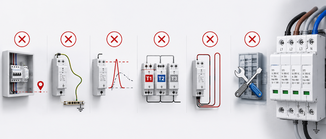
Common SPD Installation Mistakes
Even a correctly selected surge protective device may fail to provide effective protection if it is installed incorrectly. Common installation mistakes can increase the residual voltage, reduce the SPD’s service life, or prevent the surge current from being safely diverted.The following issues should be checked during installation and commissioning.
Common Mistake
Why It Is a Problem
Recommended Practice
Installing the wrong SPD type
A Type 2 or Type 3 SPD may not be able to withstand the surge energy expected at the service entrance
Match the SPD type to the installation location and surge exposure
Selecting an incorrect Uc
A Uc value that is too low may cause premature operation or damage; a value that is too high may reduce protection effectiveness
Select Uc according to the system voltage and earthing arrangement
Using excessively long connecting conductors
Long conductors add inductive voltage during surge discharge and increase the effective protection level
Keep the connection path short, direct, and free from unnecessary loops
Poor earthing or equipotential bonding
A high-impedance earth path can prevent surge current from being discharged effectively
Ensure reliable earthing and equipotential bonding
Ignoring backup protection
An internal SPD fault may not be safely disconnected from the power system
Install the fuse or circuit breaker specified by the manufacturer
Installing only one SPD in a large system
A single SPD may not provide sufficient protection for distant distribution boards or sensitive loads
Use coordinated multi-stage protection where required
Using an incorrect pole or circuit configuration
The SPD may not protect all required conductors or may be unsuitable for the earthing system
Match the SPD circuit to the phase, neutral, polarity, and grounding arrangement
Failing to coordinate multiple SPDs
A downstream SPD may absorb more surge energy than it can withstand
Use manufacturer-verified coordinated combinations
Installing the SPD too far from the protected equipment
Long downstream cables may allow additional induced surges or increase the voltage reaching the equipment
Add downstream Type 2 or Type 3 protection when necessary
Failing to inspect or replace a failed SPD
Once the SPD reaches end of life, the circuit may no longer be protected
Check the status indicator and replace failed modules promptly
To avoid these mistakes:
Select the SPD according to the system voltage, earthing arrangement, and installation location.
Keep the total connection path as short and direct as practical.
Use the correct backup protective device.
Ensure reliable earthing and equipotential bonding.
Verify coordination between upstream and downstream SPDs.
Inspect the SPD status indicator during routine maintenance.
Engineering Note The SPD itself is only one part of the surge protection system. Its actual performance also depends on conductor routing, earthing quality, backup protection, installation distance, and coordination with other SPDs. A high-performance SPD can still provide poor protection if the installation layout is incorrect.
Frequently Asked Questions About Surge Protective Devices
Can an SPD Be Used Without a Backup Fuse or Circuit Breaker?
It depends on the SPD design and the manufacturer’s installation requirements. Some SPDs require an external backup fuse or circuit breaker, while others may include integrated overcurrent protection. The backup protective device is used to disconnect the SPD safely if it develops an internal short circuit or reaches the end of its service life. Its rating should not be selected only according to the SPD’s discharge-current rating. Always follow the manufacturer’s specified maximum backup fuse or circuit-breaker rating, short-circuit current requirements, and coordination instructions.
How Should a Surge Protective Device Be Maintained?
SPD maintenance mainly involves regular inspection rather than internal repair. During routine electrical maintenance, check the status indicator, remote signaling contact, terminal tightness, signs of overheating, and the condition of the backup protective device. The SPD should also be inspected after severe thunderstorms, lightning events, major power-system faults, or repeated tripping of the upstream protective device. Replace the SPD or plug-in protection module if:
The status indicator shows failure.
A remote alarm is activated.
The enclosure is discolored, cracked, or overheated.
The backup fuse or circuit breaker has operated because of an SPD fault.
The manufacturer’s replacement criteria have been reached.
How Long Does a Surge Protective Device Last?
An SPD does not have a fixed service life. Its lifespan depends on the number, magnitude, and duration of the surges it absorbs, as well as system voltage, temporary overvoltages, environmental conditions, and product quality. An SPD may remain operational for many years in a low-surge environment, but a single severe surge can significantly reduce its remaining capacity or cause immediate failure. The status indicator and remote signaling contact should therefore be used to determine whether the SPD is still operational. Replacement should be based on actual condition and manufacturer guidance rather than a fixed number of years alone.
Do I Need Both AC and DC Surge Protection?
Both AC and DC surge protection may be required when a system contains separate AC and DC circuits. An AC SPD cannot automatically replace a DC SPD because the two devices are designed for different voltage characteristics, arc-extinguishing requirements, and system configurations. For example, a solar PV system may require:
A DC SPD on the PV array, combiner box, or inverter DC input.
An AC SPD on the inverter output or AC distribution board.
Energy storage systems, EV charging systems, and industrial DC control circuits may also require separate AC and DC protection. The selected SPD must be rated for the actual system voltage, polarity, grounding arrangement, and maximum continuous operating voltage.
Can a Damaged SPD Continue Protecting Equipment?
A damaged SPD should not be assumed to provide effective protection. Some SPDs contain an internal disconnection device that isolates the failed protection component while allowing the electrical circuit to remain energized. In this condition, the connected equipment may continue operating, but surge protection may already be partially or completely lost. If the status indicator shows failure or the remote alarm is activated, replace the SPD or protection module as soon as possible. Continuing to operate without replacement may leave downstream equipment unprotected.
Are SPDs Required for Solar PV Systems?
SPD requirements for solar PV systems depend on the applicable electrical standard, lightning protection design, installation risk, cable routing, and local regulations. PV systems are particularly exposed to induced surges because modules and DC cables are usually installed outdoors and may cover a large area. SPDs are commonly installed on the DC side, AC side, or both. Typical locations include:
PV combiner boxes
Inverter DC inputs
Inverter AC outputs
Main AC distribution boards
The required SPD type depends on whether the building has an external lightning protection system, the separation distance, the system voltage, and the lightning exposure level. Therefore, SPDs are not selected simply because the system is photovoltaic. The need, type, and installation position should be determined by the applicable project requirements and risk assessment.
LOOKING FOR A SUITABLE SPD FOR YOUR PROJECT?
After understanding the different SPD types, selection parameters, installation locations, and coordination requirements, you may also explore our complete range of surge protective devices for AC and DC applications. Visit our Surge Protective Devices (SPD) product category to compare available models, voltage ratings, discharge current levels, pole configurations, and application options.
ABOUT THIS GUIDE
This guide was prepared to help engineers, panel builders, electrical contractors, system integrators, and industrial buyers better understand surge protective devices (SPDs), their operating principles, selection criteria, installation practices, and common applications.
Electrical Engineer | Low-Voltage Power Distribution
Hello, I’m Evan.
I am an electrical engineer with 10 years of experience in low-voltage electrical equipment, circuit protection, and power distribution systems. I specialize in product selection, application engineering, and technical support for industrial, commercial, and renewable-energy projects.
For technical inquiries, please contact me at evan@jutrion.com.