

실제 엔지니어링 환경에서 정전은 결코 “몇 분간의 어둠”에 그치지 않습니다. 데이터 센터나 병원의 경우, 단 몇 초의 전원 중단만으로도 재앙이 될 수 있습니다. 산업 생산 라인에서는 예기치 못한 전압 강하로 인해 원자재 전체 배치가 폐기되고 장비 재가동에 오랜 시간이 걸릴 수 있습니다. 고급 상업용 건물에서도 소방 및 보안 시스템의 고장은 용납할 수 없는 위험입니다.
자동 전환 스위치(ATS)는 이러한 전원 공급 생명선의 “최후의 방어선”입니다. 이중 전원 시스템의 핵심 허브로서, 주 전원에 저전압, 정전 또는 결상이 발생하면 ATS는 매우 짧은 시간 내에 정확한 판단을 내려 중요 부하를 백업 전원으로 안전하게 전환하고, 주 전원 공급이 완전히 안정된 후에만 원활하게 다시 전환해야 합니다.
많은 프로젝트에서 조달 단계에서 치명적인 실수를 범합니다. ATS를 단순한 “대형 스위치”로 간주하고 정격 전류만 올바르게 선택하면 된다고 가정하는 것입니다. 실제로 ATS는 두 전원 사이의 “교통 관제사”입니다. 발전기 전압 확립 지연, 중성선 전환 전략(극 선택), 상하위 차단기와의 단락 보호 협조에 이르기까지, 이러한 세부 사항 중 하나라도 잘못 결정되면 중요한 순간에 전체 시스템이 고장날 수 있습니다.
아직 프로젝트의 장비 평가 단계에 있다면, 먼저 당사의 [자동 전환 스위치(ATS) 핵심 제품 섹션],을(를) 살펴보시기 바랍니다. 그러면 시스템에 가장 적합한 기본 아키텍처를 빠르게 파악할 수 있습니다.
국제 프로젝트에서 ATS 선정은 제품 카탈로그에만 의존해서는 안 됩니다. 제품 뒤에 있는 적용 가능한 표준과 규정을 기준으로 평가해야 하며, 여기에는 다음이 포함됩니다. IEC 60947-6-1 — 전원 공급 연속성 보장을 위한 전환 스위칭 장비, NFPA 70 (NEC) — 미국 프로젝트의 안전한 전기 설계 및 설치, NFPA 110 — 건물 및 시설의 비상 및 예비 전원 시스템.
자동 전환 스위치(ATS)란 무엇인가?
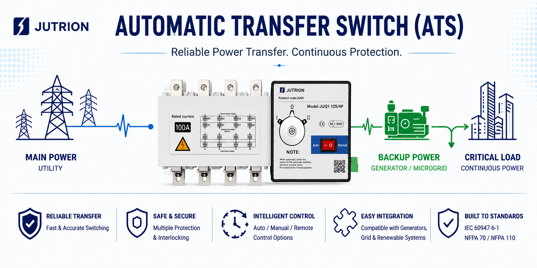
자동 전환 스위치(ATS)는 이중 전원 공급 시스템에 사용되는 중요한 스위칭 장치입니다. 일반적으로 주 전원과 백업 전원 사이에 설치되어 필요할 때 부하를 한 전원에서 다른 전원으로 전환할 수 있게 합니다. 일반적인 전원 조합으로는 상용 전원-발전기, 상용 전원-상용 전원, 상용 전원-에너지 저장 장치 또는 인버터 출력 등이 있습니다.
기존 차단기와 달리 ATS의 주 목적은 고장 전류를 직접 차단하는 것이 아닙니다. 핵심 기능은 사용 가능한 두 전원 간의 신뢰성 있고 제어되며 적절하게 인터로크된 전환을 보장하는 것입니다. 이러한 이유로 ATS 설계는 일반적으로 스위칭 메커니즘, 제어 로직, 전원 모니터링, 기계적 및 전기적 인터로크, 그리고 전체 전원 공급 시스템의 연속성을 중심으로 이루어집니다.
엔지니어링 관점에서 ATS는 본질적으로 전원 공급 연속성을 유지하기 위한 장치입니다. IEC는 또한 전환 스위칭 장비 및 자동 전환 스위칭 장비에 대한 명확한 표준 프레임워크를 제공합니다. 따라서 수출 프로젝트, EPC 프로젝트 및 국경 간 엔지니어링 응용 분야에서 ATS의 적용 표준, 시험 문서 및 작동 한계는 모두 중요한 고려 사항입니다.
주 전원과 백업 전원 사이에서 ATS가 작동하는 방식
ATS가 주 전원과 백업 전원 사이에서 작동하는 과정은 주로 실시간 모니터링, 고장 판단, 신뢰성 있는 절체, 자동 복귀 절체를 포함합니다. 전체 과정은 완전 자동이며 안전 인터로크를 갖추고 있으며, 구체적으로 네 단계로 나눌 수 있습니다.
정상 작동 단계 (주 전원 공급 활성)
기본적으로 ATS는 부하에 주 전원(상용 전원), 으로부터 전력을 공급하는 동시에, 컨트롤러는 전압, 주파수, 위상 상태 등 주 전원의 주요 파라미터를 24시간 연속으로 모니터링합니다. 백업 전원은 상시 대기 상태를 유지하며, 주 전원과 백업 전원의 절체 장치는 기계적 및/또는 전기적으로 인터로크되어 동시 투입을 엄격히 방지, 하여 두 전원 간의 단락을 방지합니다.
주 전원 고장 단계 (절체 트리거)
주 전원에 정전, 저전압, 과전압, 결상 또는 비정상 주파수가 발생하면, ATS는 먼저 설정 가능한 고장 확인 지연 (일반적으로 0.5~5초)을 적용하여 순간적인 변동을 걸러냅니다. 고장이 실제임이 확인되면 다음 순서가 진행됩니다.
- 컨트롤러가 메커니즘을 구동하라는 명령을 보내 주 전원 스위치를 개방;
- 합니다. 주 전원 스위치가 완전히 개방된 후 백업 전원 스위치가 투입됩니다. 일부 애플리케이션에서는 발전기가 기동하여 정격 전압과 주파수에 도달하는 등 백업 전원이 안정될 때까지 먼저 기다려야 합니다.;
- 그런 다음 부하가 백업 전원으로 절체됩니다. 전체 과정은 일반적으로 밀리초 내에 완료되므로, 중요 부하는 거의 또는 전혀 감지할 수 없을 정도의 중단만 경험할 수 있습니다.
백업 전원 공급 단계
ATS는 백업 전원에서 부하로 안정적인 전력을 공급하면서 주 전원의 복구 상태를 계속 모니터링합니다. 일부 모델에는 백업 전원 고장 모니터링도 포함되어 있어 두 전원이 동시에 고장 날 위험을 줄이는 데 도움이 됩니다.
주 전원 복구 단계 (자동 재절체)
주 전원의 전압과 주파수가 허용 범위로 복귀하고 일정 시간(설정 가능, 예: 1~30분) 동안 안정적으로 유지되면, ATS는 자동으로 백업 전원에서 주 전원으로 재절체:
- 를 수행합니다. 먼저 백업 전원 스위치를 개방한 다음 주 전원 스위치를 투입합니다.;
- 부하가 주 전원으로 다시 절체되고, 백업 전원은
핵심 안전 설계: ATS는 기계적 및/또는 전기적 인터로크 메커니즘을 사용하여 어떤 상황에서도 주 전원 스위치와 백업 전원 스위치가 동시에 투입될 수 없도록 보장하며, 순환 전류 및 단락과 같은 치명적인 위험을 완전히 방지합니다. 이것이 바로 ATS와 일반 이중 스위치 배열의 가장 근본적인 차이점입니다.
자동 절체 스위치(ATS)의 주요 구성 요소
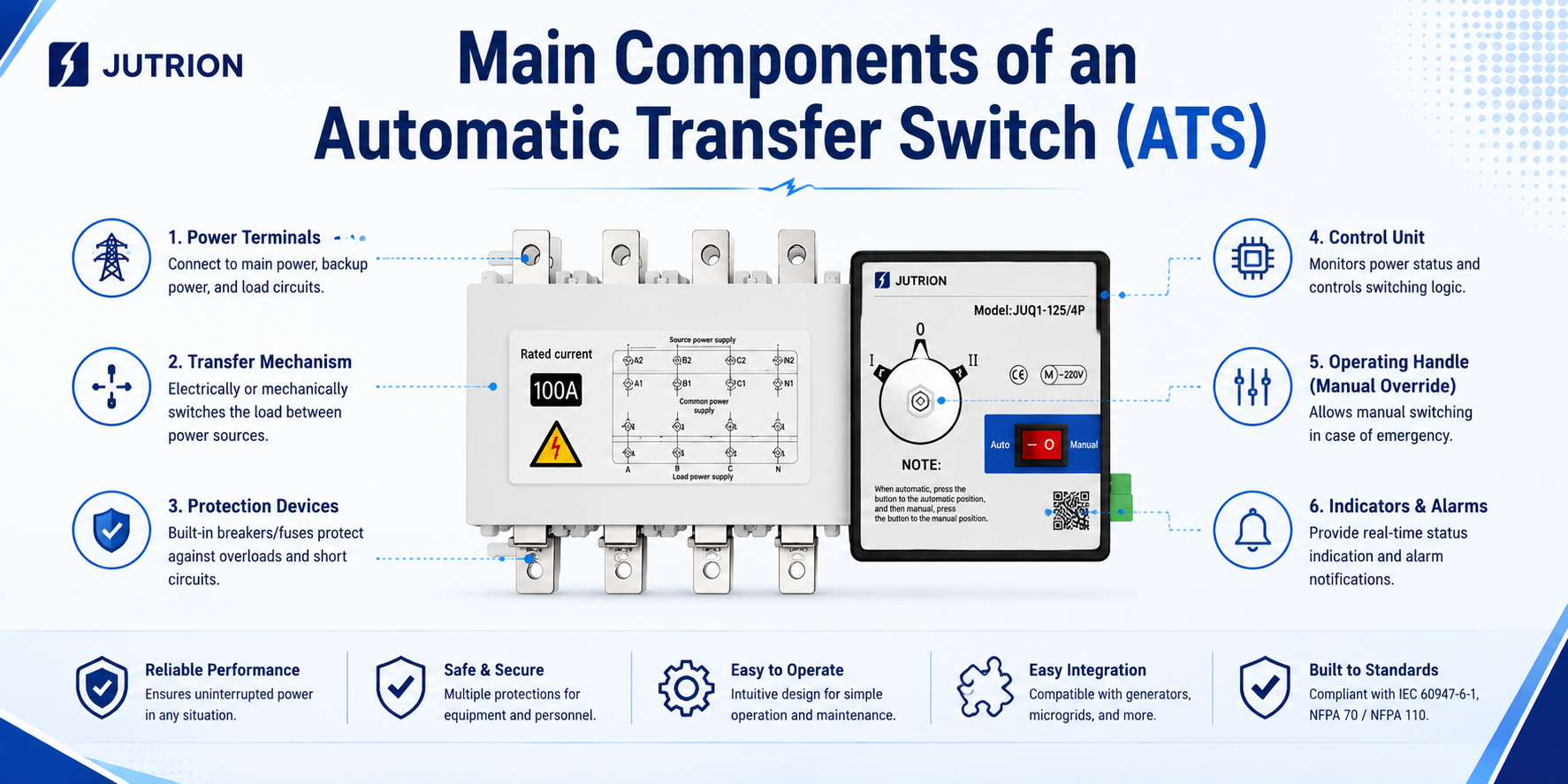
ATS는 단일 절체 장치가 아니라 모니터링, 제어, 작동 및 안전 보호를 통합한 완전한 시스템입니다. 핵심 구성 요소는 크게 네 가지 주요 모듈로 나뉘며, 이들이 함께 전원 상태 모니터링, 고장 감지, 안전 절체 및 자동 재절체의 전체 과정을 가능하게 합니다. 다음과 같습니다.
이중 전원 절체 본체 (작동 메커니즘)
이것은 ATS의 핵심 실행 유닛 ATS의 핵심 실행 장치로, 주 전원과 예비 전원 간의 물리적 전환을 담당합니다. 일반적으로 두 가지 주요 형태로 나뉩니다:
- 일체형 PC급 ATS: 단일 통합형 전환 스위치로, 전용 기계적 인터로킹 구조를 갖추고 있으며 “선 차단 후 투입(break-before-make)” 동작을 구현하도록 설계되었습니다. 비교적 높은 단락 전류를 견딜 수 있으며 중요 부하 용도에 널리 사용됩니다.
- CB 클래스 ATS: 두 대의 차단기(또는 단로기)와 기계적 및/또는 전기적 인터로킹으로 구성됩니다. 보호 기능과 전환 기능을 모두 제공하며 일반적으로 비용이 더 낮고, 일반적으로 중요한 부하에 흔히 사용됩니다.
지능형 컨트롤러(제어 두뇌)
이는 ATS의 “의사 결정 센터”로, 전원 상태 감시와 전환 로직 제어를 담당합니다:
- 두 전원의 전압, 주파수, 결상, 과전압, 저전압 등의 파라미터를 실시간으로 감시합니다.;
- 지연 확인(오동작 방지), 고장 전환, 예비 전원에서 주 전원으로의 재전환, 발전기 기동/정지 연동 등의 로직을 실행합니다.;
- 현장/원격 제어, 상태 표시, 고장 경보, 통신 인터페이스(예: Modbus) 등의 기능을 제공합니다.
구동 및 인터로킹 기구(안전 코어)
- 구동 기구: 전동기 작동식, 전자기식 또는 스프링 에너지 저장식일 수 있으며, 스위치 본체에 전환력을 제공하고 신뢰성 있는 동작을 보장합니다.;
- 인터로킹 기구: 기계적 및 전기적 인터로킹을 모두 채택하여 주 전원과 예비 전원이 동시에 투입되는 것을 엄격히 방지하고, 두 전원 간의 단락 및 순환 전류 사고를 완전히 차단합니다. 이는 ATS를 일반 이중 스위치 배열과 구별하는 핵심 안전 설계입니다.
보조 및 지원 부품
- 전원 샘플링 유닛: 두 전원의 전압 및 전류 신호를 컨트롤러에 제공합니다.
- 상태 피드백 접점: 스위치의 개방/투입 위치와 고장 상태를 외부 시스템으로 피드백합니다.
- 발전기 제어 인터페이스: 일부 ATS 유닛은 발전기 기동 및 정지를 제어하는 신호를 직접 출력하여, 상용 전원 고장 시 발전기가 자동으로 기동하여 전력을 공급하도록 할 수 있습니다.;
- 조작 패널 / 디스플레이 화면: 파라미터 설정, 수동/자동 전환 제어 및 작동 상태 표시에 사용됩니다.
보충 설명:
서로 다른 유형의 ATS 핵심 부품의 차이는 본질적으로 IEC 표준에 따른 서로 다른 구현 형태입니다. 예를 들어, PC Class ATS와 CB Class ATS의 차이는 주로 스위치 본체의 구조 설계와 보호 능력 수준에 반영되며, 컨트롤러 및 인터로킹 기구와 같은 핵심 안전 모듈의 설계 로직은 모두 해당 표준의 필수 요구 사항을 준수해야 합니다.
빠른 ATS 선정 체크리스트
✅ 부하 범주 및 적용 시나리오 확인 완료
✅ 정격 전류 및 프레임 크기가 부하 및 단락 요구 사항을 충족함
✅ 극수(3P/4P)가 시스템 구성과 일치함
✅ ATS 유형(PC Class / CB Class)이 요구되는 부하 신뢰성 수준과 일치함
✅ 제어 모드 및 지연 파라미터를 현장 조건에 따라 조정 가능함
✅ 추가 기능(인터로킹 / 통신 / 바이패스)이 필요에 따라 구성됨
✅ 상·하위 보호 장치, 발전기 및 화재 방지 시스템과의 협조 로직이 명확히 정의됨
적용 분야부터 시작: 부하 수준과 프로젝트 요구 사항을 먼저 정의하십시오
핵심 파라미터 확인: 주요 지표를 우선시하십시오
정격 전류 및 프레임 크기
- 정격 전류(Ie): 최소 25배 이상이어야 하며, 기동 전류와 장기 운전 여유를 고려해야 합니다. 예를 들어, 부하 전류가 160A인 경우 200A 또는 250A ATS를 선택해야 합니다.
- 프레임 크기: 시스템 단락 전류에 따라 선택해야 하며, 정격 단시간 내전류(Icw) 요구 사항을 충족하여 고장 조건에서 소손을 방지해야 합니다.
극수 선택(P)
- 3P ATS: 중성선이 전환에 참여하지 않는 3상 3선식 시스템에 적합합니다. TN/IT 시스템에 적용 가능하며 일반적으로 비용이 더 저렴합니다.
- 4P ATS: 중성선이 동시에 전환되는 3상 4선식 시스템에 적합합니다. 중성점 이동, 심각한 고조파 왜곡 또는 두 전원 간 비공통 중성선이 있는 시나리오(병원 및 데이터 센터 등)에 적용 가능하며, 중성선 순환 전류 방지에 도움이 됩니다.
유형 선택: PC급 vs CB급(핵심 차이점)
| 구분 | PC Class ATS | CB 클래스 ATS |
| Core structure | Integrated transfer switch with dedicated mechanical interlocking | Two circuit breakers with interlocking mechanism |
| Protection function | Transfer function only, without short-circuit or overload protection | Built-in circuit breaker protection, capable of short-circuit interruption |
| Short-circuit withstand capability | High, able to withstand large short-time current impact | Depends on the breaking capacity of the circuit breakers and requires coordination with upstream and downstream protection |
| Transfer speed | Faster, typically 10–50 ms | Slower, typically 100–500 ms |
| Typical applications | Critical loads, generator power supply, and systems with high short-circuit current | Generally important loads and applications requiring built-in protection |
Control and Transfer Modes
- Control modes: automatic (priority), manual, and remote control (Modbus / dry contact), to be selected according to operation and maintenance requirements.
- Transfer modes:
Automatic transfer and automatic retransfer: after the main power source recovers, the load is automatically transferred back to utility power. This is suitable for applications where utility power is the preferred source.
Automatic transfer without automatic retransfer: after switching to the backup power source, the ATS remains in that state and requires manual reset. This is suitable for applications where utility power quality is poor or fluctuates frequently. - Delay settings: fault confirmation delay (to filter out momentary fluctuations), generator start delay, and utility power recovery delay should all be adjusted according to actual site conditions.
Additional Functional Requirements
- Generator linkage: can directly output start/stop signals to enable automatic generator startup when utility power fails.
- Bypass function: supports online maintenance of the ATS without interrupting the load power supply, suitable for high-reliability applications.
- Communication function: Modbus/RS485 interfaces allow integration with building automation or power monitoring systems.
- Fire protection linkage: supports forced fire control logic and disconnects the power supply to non-firefighting loads in the event of a fire.
Key Pitfalls to Avoid During ATS Selection
- Neutral handling: for 4P ATS, special attention should be paid to the switching sequence of the neutral conductor to avoid load overvoltage caused by opening the neutral before closing it again. In TN-S systems, if the neutrals of both power sources share a common grounding point, a 3P+N solution (neutral makes first and breaks last) may be considered first.
- Short-circuit protection coordination: the interrupting capacity of the circuit breakers used in CB Class ATS must be higher than the prospective short-circuit current of the system, and selective coordination with the upstream circuit breaker should also be achieved to avoid nuisance tripping at higher levels.
- Transfer time coordination: for critical loads, such as those located downstream of a UPS, it is necessary to confirm whether the ATS transfer time is within the acceptable range of the load, so as to avoid UPS battery discharge or load restart caused by the transfer process.
- Environmental adaptability: in high-temperature, humid, or dusty environments, models with an IP protection rating of at least IP40 should be selected, and cabinet ventilation or dehumidification devices should be added when necessary.
Environmental adaptability: in high-temperature, humid, or dusty environments, models with an IP protection rating of IP40 or above should be selected, and cabinet ventilation or dehumidification devices should be added when necessary.
PC Class vs CB Class ATS: What’s the Difference?
PC Class Automatic Transfer Switch
Standard definition: a transfer switching device that is only capable of making, carrying the rated operating current, and withstanding the rated short-time current, but does not have the ability to interrupt short-circuit current.
Product positioning: a device dedicated purely to power source transfer. It does not include overload or short-circuit trip protection mechanisms. Its core function is only to ensure reliable transfer between two power sources, while system fault protection is provided by upstream devices such as circuit breakers and fuses.
CB Class Automatic Transfer Switch
Standard definition: a transfer switching device equipped with an overcurrent trip device, whose contacts are capable of making and carrying current, and which can also directly interrupt short-circuit fault current.
Product positioning: composed of two circuit breakers together with an interlocking mechanism, it combines both power source transfer and overload/short-circuit fault protection functions, and can itself interrupt fault current in the circuit.
Typical Applications of PC Class ATS
- Critical Level 1 loads such as hospitals, data centers, and financial server rooms, where power interruption may lead to major losses;
- Emergency power supply circuits for fire pumps, smoke exhaust fans, and other firefighting systems;
- Dual-power supply systems used together with generator sets;
- Precision industrial control production lines with extremely high requirements for outage duration and transfer stability.
Typical Applications of CB Class ATS
- Level 2 power supply loads in office buildings, shopping malls, and general commercial buildings;
- Small equipment rooms, emergency lighting, and residential backup power supply;
- Conventional power distribution projects with limited budget and relatively low short-circuit current in the circuit.
Key Considerations for Selection
- PC Class ATS must be coordinated with upstream protective devices and cannot be used alone as a fault protection switch;
- CB Class ATS usually has a longer transfer time, so it should be used with caution for sensitive electronic loads to prevent unexpected shutdown or restart of equipment;
- In many locations, fire protection codes require the use of PC Class ATS to ensure that emergency power supply remains effective.
If your project involves upstream protection coordination, you may also refer to our MCCB product page and ACB product page for more information on protection coordination and system matching.
ATS Installation and Wiring Considerations
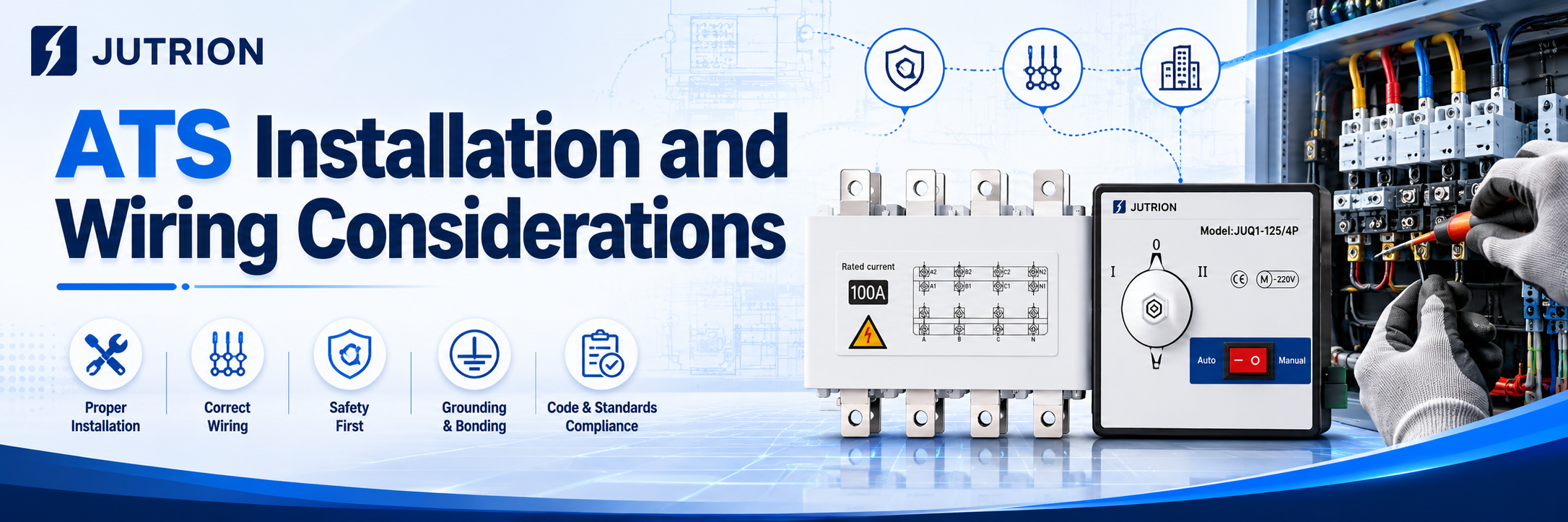
Key Installation Requirements
Installation environment:
Avoid humid, dusty, corrosive gas, and strong vibration areas. The ambient temperature should be controlled within -25°C to +40°C, the cabinet should have good ventilation and heat dissipation, and the protection rating should match the actual site conditions.
Installation fixing:
Install the ATS vertically in the upright position. The cabinet should remain level and stable, with sufficient space reserved for inspection and operation. Inclined or inverted installation is strictly prohibited. When multiple units are arranged together, adequate spacing for heat dissipation should be reserved.
Safety clearance:
Standard electrical clearance should be maintained between different phase conductors and between incoming and outgoing lines. The insulation withstand requirements must be met to prevent creepage and phase-to-phase discharge.
Grounding requirements:
The equipment enclosure and cabinet must be reliably grounded. The grounding conductor specification should comply with the applicable electrical code requirements to eliminate potential electric leakage hazards.
Core Wiring Requirements
Phase sequence verification:
Strictly distinguish the incoming phase sequence of the normal power source and the backup power source, and ensure that the phase positions of both power sources are consistent. Incorrect phase sequence may cause transfer failure or equipment damage.
Separation of incoming and outgoing lines:
The incoming terminals are connected to the main and backup power sources, while the outgoing terminals are uniformly connected to the downstream load. Reverse wiring or mixed wiring is not allowed. Wiring must follow the terminal layout and identification marks of the equipment.
Cable selection:
The conductor current-carrying capacity must be greater than the rated current of the switch, and should meet the requirements for voltage drop and temperature rise. Wiring terminals must be firmly tightened to prevent false contact and overheating caused by looseness.
Neutral conductor handling:
3P/4P switches must be wired according to the system configuration. The neutral conductors of the two power sources must never be mixed or incorrectly connected, so as to avoid neutral circulating current and voltage shift problems.
Control circuits:
Secondary control wiring should be arranged neatly, with strong-current and weak-current circuits routed separately to reduce electromagnetic interference. Interlocking, communication, and generator start/stop circuits must be wired according to the drawings.
Inspection and Commissioning After Wiring
- Before energizing, check whether there is any short circuit, incorrect wiring, or missed connection, and tighten all wiring points.
- Test the automatic transfer function and manual transfer function in sequence, and verify that the actions of fault power-off and utility power recovery transfer-back are normal.
- Verify the delay parameters, protection logic, and interlocking signals to ensure they are consistent with the design scheme.
- During trial operation, observe the temperature rise of the switch, abnormal noise, and indicator light status. The ATS can only be put into formal operation when no abnormality is found.
Prohibited Actions
It is strictly forbidden to dismantle the mechanical and electrical interlocking mechanism without authorization; it is prohibited to manually close the two power sources in parallel; overload connection to the load is not allowed; and it is strictly forbidden to open the cover for wiring or disassembly while energized.
Common ATS Selection Mistakes and Troubleshooting Resources
The most common selection mistakes include choosing the ATS only according to load current without leaving a margin, mistaking an ATS for a UPS, failing to verify the pole configuration, overlooking generator start signal requirements, ignoring generator voltage build-up delay, failing to consider high-temperature derating, and directly applying a conventional generator-based solution to solar PV or energy storage systems.
Key Takeaways:
If ATS is treated simply as “just another ordinary switch to buy,” it will almost certainly create hidden risks later, such as wiring confusion, incorrect transfer actions, and even improper upstream tripping. A selection logic that can truly stand up to real-world testing must always follow this principle: define the system boundaries first, and then define the product parameters. Only after the system structure and application scenario are clearly understood should the pole configuration, control strategy, and protection coordination be determined, so that the final product model can be selected accurately.
Different types of projects have fundamentally different technical demands for ATS:
Residential buildings and commercial complexes: the core requirement is absolute reliability of basic switching action together with a balanced budget.
Large industrial facilities and critical infrastructure: priority must be given to upstream and downstream protection coordination, as well as the ability to withstand extreme short-circuit fault conditions.
Renewable energy and microgrid systems: low-level control logic compatibility and inverter coordination have become new technical priorities.
Therefore, it is meaningless to discuss ATS selection without reference to the actual system architecture. That is the essence of engineering design: there is no “one-size-fits-all” model here, only a solution tailored specifically to your system.
There is no universal ATS solution for every project. If you need help evaluating your system architecture, pole configuration, or protection coordination, you are welcome to contact our engineering team for professional support.
Frequently Asked Questions About ATS:
Q: If a PC Class ATS is used, is an upstream circuit breaker such as an MCCB or ACB still required?
A:Yes, it is absolutely necessary. A PC Class ATS is like the “railway switch operator” in a power distribution system: it is only responsible for changing the track, that is, switching the power source, but it is not responsible for braking, that is, interrupting short-circuit faults.
When a severe short circuit occurs, it can only withstand the extremely high rated short-time withstand current (Icw) for a short period, while waiting for the upstream MCCB or ACB to trip and clear the fault.
Without a circuit breaker acting as its protection, a PC Class ATS is very dangerous under short-circuit conditions.
Q:How should the rated current be selected? Is it enough to simply add up the load power shown on the drawings?
A:Never select it right at full-load current. Real engineering conditions are far more complicated than theoretical calculations. If the temperature inside the distribution cabinet rises to 50°C or even 60°C in summer, the equipment must operate under derating conditions. In addition, inductive loads such as pumps and fans can produce high inrush current during startup. For this reason, we usually recommend leaving at least a 20% safety margin above the actual maximum operating current.
Q:Can two power sources with different voltage levels share the same ATS?
A:This is strongly not recommended unless a specially customized controller is used. The ATS controller usually needs to sample the voltage of both power sources at the same time for comparison and decision-making. If the two power sources are not at the same voltage level, the control logic may become completely disordered.
In standard engineering practice, the proper solution is to first unify the voltage reference through a transformer and then perform the transfer.
