

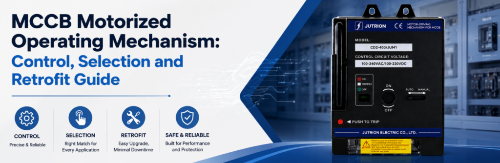
MCCB 전동 조작 기구 제어, 선정 및 개조 가이드빠른 답변: MCCB 모터 조작기는 무엇을 합니까?
한 MCCB 전동 조작 기구, (MCCB 모터 조작기라고도 함)는 명령에 따라 호환 배선용 차단기를 기계적 상태 간에 이동시키는 전기 액추에이터입니다. 차단기와 일치하는 기구에 따라 차단기를 열고, 닫고, 트립 후 리셋할 수 있습니다. 원격으로 차단기를 닫을 수 있는 유일한 차단기 액세서리입니다 — 션트 트립과 부족전압 릴리스는 열기만 할 수 있습니다.
제어실에서 피더 차단기에 CLOSE 명령을 보냈지만 아무 일도 일어나지 않습니다. 일반적인 첫 번째 가정은 모터 고장입니다. 모터는 종종 정상입니다. 차단기가 여전히 TRIPPED 상태이거나, 셀렉터가 MANUAL에 있거나, 투입 허용 조건이 누락되었거나, 작동 중에 제어 전원이 붕괴되었을 수 있습니다.
이것이 이 가이드의 핵심입니다. 모터 조작기는 핸들을 돌리는 전기 손이 아닙니다. 자동화 시스템이 명령을 내리고, 허용 로직이 허용 여부를 결정하고, 기구가 차단기를 움직이고, 보조 접점이 결과를 확인하는 체인의 한 링크입니다. 어떤 링크라도 지정되지 않으면 “원격 MCCB 작동”은 완전한 기능이 아닙니다.
모터 조작기는 또한 보호 장치가 아닙니다. 전류를 감지하지 않고, 고장 시 트립하지 않으며, 차단기의 Icu 를 높이거나 트립 유닛을 변경하지 않습니다. 또한 접촉기를 대체하지도 않습니다. 모터 조작기가 있는 차단기는 빈번하지 않은 작동용으로 제작되었으며, 모터 회로가 요구하는 하루 수천 회의 사이클용이 아닙니다.
이 가이드를 세 단계로 사용하십시오:
- 프로젝트에 원격 개방만 필요한지, 아니면 원격 리셋 및 투입도 필요한지 확인하십시오.
- 기계적 호환성, 제어 전압, 기동 수요 및 케이블 전압 강하를 확인하십시오.
- 허용 조건, 피드백, 인터로킹 및 보호 트립 후 동작을 정의하십시오.
사양 요약
| 결정 사항 | 결정 기준 | 구매자가 잘못하는 점 |
|---|---|---|
| 액세서리 유형 | 트립만이 아닌 원격 투입 이 필요한지 여부 | “원격 제어”를 위해 션트 트립을 주문하는 것” |
| 필요한 동작 | 개방만, 또는 트립 후 개방–리셋–투입 | “원격 투입”에 TRIPPED에서의 리셋이 포함된다고 가정하는 것 |
| 기계적 적합성 | 명판에서 확인하는 차단기 시리즈, 프레임, 극수 및 장착 방식 | 정격 전류만으로 매칭하는 것 |
| 제어 전압 | 실제 케이블 경로에 대한 전압 강하 | 긴 경로에 습관적으로 24 V DC를 선택하는 것 |
| 제어 전원 용량 | 결합 기동(돌입) VA와 프로젝트 전원 공급 장치 여유 | 유지 부하로 용량을 산정하는 것 |
| 피드백 | 위치 접점과 별도의 트립/알람 접점 | 모든 것을 하나의 보조 접점으로 처리하는 것 |
| 사용 빈도 | 정격 내구성 대비 연간 작동 횟수 | 접촉기가 필요한 곳에 차단기를 사용하는 것 |
원격 작동은 두 가지가 아닌 세 가지 차단기 상태에서 시작됩니다
수동 스위치는 ON 또는 OFF입니다. MCCB에는 모든 원격 제어 설계를 지배하는 세 번째 상태인 TRIPPED가 있습니다. 투입 명령은 트립된 차단기를 단순히 열린 것처럼 취급할 수 없습니다.
켜짐 은 주 접점이 닫혀 있음을 의미합니다. 모터 조작기는 차단기가 이미 닫혀 있을 때 반복적인 투입 명령을 받지 않아야 하며, 이것이 마지막 명령이 성공했다고 가정하는 것보다 위치 피드백이 더 신뢰할 수 있는 이유입니다.
꺼짐 접점이 열려 있고 허용 조건이 충족되면 기구가 정상 투입 동작을 할 준비가 되었음을 의미합니다. OFF 표시가 해당 회로가 작업하기에 안전함을 증명하지는 않습니다. 절연, 잠금 및 무전압 확인은 별도의 요구 사항으로 남습니다.
트립됨 기구가 보호 해제 또는 트립 명령에 응답했음을 의미합니다. 차단기가 다시 투입되려면 먼저 기구가 일반적으로 리셋 동작을 거쳐야 합니다. 고장 트립은 단순한 핸들 위치 변화가 아니라 정보입니다.
| 관찰된 상태 | 제어 시스템에 대한 의미 | 허용되는 다음 조치 | 필요한 피드백 |
|---|---|---|---|
| 켜짐 | 주 접점 투입됨 | 유지하거나 필요 시 OPEN 발령 | 위치 접점 |
| 꺼짐 | 접점 열림, 기구 투입 준비 완료 | 허용 조건이 참일 때만 CLOSE | 열림 위치 표시 및 투입 허용 상태 |
| 트립됨 | 보호 또는 원격 트립이 작동함 | 점검하고, 권한이 있으면 리셋한 후 투입 재평가 | 정상 OFF와 구별되는 트립/경보 표시 |
| 이동 중 또는 미확인 | 기구 작동 중, 정지됨 또는 피드백 불일치 | 타임아웃 및 진단까지 추가 명령 차단 | 명령 타이머 + 위치 비교 |
리셋 이동은 별도의 기계적 요구 사항입니다
보호 트립 후 많은 차단기는 기구가 리셋되기 전에 핸들이 정상 OFF 위치를 지나 이동해야 합니다. ON/OFF 전환 전용 모터 조작기는 그러한 이동을 제공하지 못할 수 있습니다. “원격 투입”에 포함되어 있다고 가정하지 말고 “트립 후 원격 리셋”을 명시적으로 지정하십시오.
리셋은 피드백 로직도 변경합니다. 기구가 리셋되면 경보 접점이 해제될 수 있지만, OFF 보조 접점은 이미 주 접점 열림 상태를 표시할 수 있습니다. 제어기가 OFF만으로 증명한다면 차단기가 여전히 기계적으로 트립된 상태에서 CLOSE를 발령할 수 있습니다.
모터 조작기, 션트 트립 또는 부족전압 릴리스: 작업에 맞는 액세서리 선택
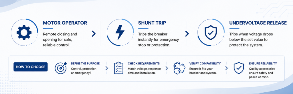
MCCB 액세서리 선택을 위한 모터 조작기 vs 션트 트립 vs 부족전압 릴리스원격 제어는 이러한 액세서리들이 상호 교환 가능한 것으로 취급되기 때문에 종종 과도하게 지정됩니다. 이들은 상호 보완적이며, 이 범주에서 가장 비용이 많이 드는 오해는 션트 트립을 구매한 후 그것이 차단기를 다시 투입할 수 없다는 것을 발견하는 것입니다.
| 기능 | 모터 조작기 | 션트 트립 (MX) | 부족전압 릴리스 (MN) | 보조 접점 (OF) |
|---|---|---|---|---|
| 차단기를 원격으로 투입 | 예, 일치하는 설계가 허용하는 경우 | 아니요 | 아니요 | 아니요 |
| 차단기를 원격으로 개방 | 예 | 예 | 예, 전원 상실 시 | 아니요 |
| 트립 후 리셋 | 모델별 상이 — 확인 필요 | 아니요 | 아니요 | 아니요 |
| 차단기 위치 보고 | 단독으로는 불가 | 아니요 | 아니요 | 예 |
| 연속 전원 필요 | 아니요 — 작동 중에만 소비 | 아니요 — 트립 시에만 여자됨 | 예 — 여자 상태 유지 | 아니요 — 무전압 |
| 제어 전원 상실 시 | 차단기는 상태 유지, 원격 제어 불가 | 트립 불가 | 트립됨 — 본질적으로 페일 세이프 | 접점 상태 무변화 |
| 일반적인 역할 | 원격 개방, 리셋 및 투입 조작기 | 화재 경보 또는 비상 트립 경로 | 페일 세이프 트립 및 투입 허가 | 명령 확인 및 인터로킹 |
마지막 두 행을 함께 읽으십시오. 션트 트립은 제 기능을 수행하기 위해 정상적인 제어 전원이 필요합니다. 반면 저전압 릴리스는 전원이 상실될 때 바로 제 기능을 수행합니다. 제어 전원 자체가 고장날 경우 어떤 일이 일어나야 하는지를 물어 그 둘 중에서 선택하십시오. 모터 조작기는 다른 질문에 답합니다. 차단기 앞에 아무도 서 있지 않을 때 누가 차단기를 투입하는가 하는 것입니다.
모터 조작기는 차단기를 기계적으로 개방할 수 있으며, 프로젝트는 여전히 보호 또는 비상 회로가 독립적이고 정의된 트립 경로를 필요로 하는 경우가 많기 때문에 션트 트립을 요구할 수 있습니다. 이들은 서로 선택하는 것이 아니라 함께 장착됩니다.
모터 조작기가 실제로 차단기를 움직이는 방식
명령이 메커니즘에 도달하면 기어드 모터가 작동하고 차단기가 상태를 변경합니다. 그 사이에 일어나는 일은 설계에 따라 다르며, 그 차이는 명령 지속 시간, 타이밍 및 정전 후 제어기가 예상해야 할 사항에 영향을 미칩니다.
직접 구동. 모터는 전원이 공급되는 동안 전체 행정을 통해 조작 인터페이스를 움직입니다. 명령은 전체 이동에 충분한 시간 동안 유지되어야 하며, 조작기 움직임은 대체로 차단기 핸들을 따르므로 시운전 중 동작을 쉽게 관찰할 수 있습니다.
축적 에너지. 모터가 스프링을 충전하고, 스프링이 방출되면서 접점을 한 번의 빠른 동작으로 움직입니다. 이는 접점 속도를 모터 속도에서 분리하여, 접점이 사전 아크 발생을 제한할 만큼 충분히 빠르게 투입될 수 있게 합니다. 충전 시퀀스와 접점 동작은 두 개의 별도 이벤트이며, 제어기는 둘 다를 고려해야 합니다.
어느 방식이 보편적으로 더 낫다고 할 수 없습니다. 결정적인 질문은 완전한 차단기-메커니즘 조립체가 사용 가능한 제어 전원으로 그리고 프로젝트 타이밍 내에서 요구되는 개방, 리셋 및 투입 시퀀스를 수행하는지 여부입니다. 두 경우 모두 동작이 완료되면 모터가 정지하므로, 모터 조작기는 큰 순간 수요를 나타내지만 실질적인 상시 부하는 없습니다.
어느 방식이든 수동 조작은 정의된 상태로 유지되어야 합니다. 현재 JUTRION 포트폴리오 페이지에는 모터 구동 조작 메커니즘 제품군에 내장형 자동/수동 스위치가 나열되어 있습니다. 주문한 모델의 기계적 결합, MANUAL이 원격 명령을 차단하는지 여부, 모터 전원을 분리하는지 여부, 제어기가 선택기 위치 피드백을 수신하는지 여부를 확인하십시오. 수동 선택기는 절연 장치가 아니며 패널의 잠금 절차와 조정되어야 합니다.
명령, 허가, 동작 및 피드백 체인 구축
신뢰할 수 있는 모터 제어 회로에는 네 가지 연결된 기능이 있습니다. 각각 정의된 입력, 출력, 고장 응답 및 시운전 테스트가 필요합니다.
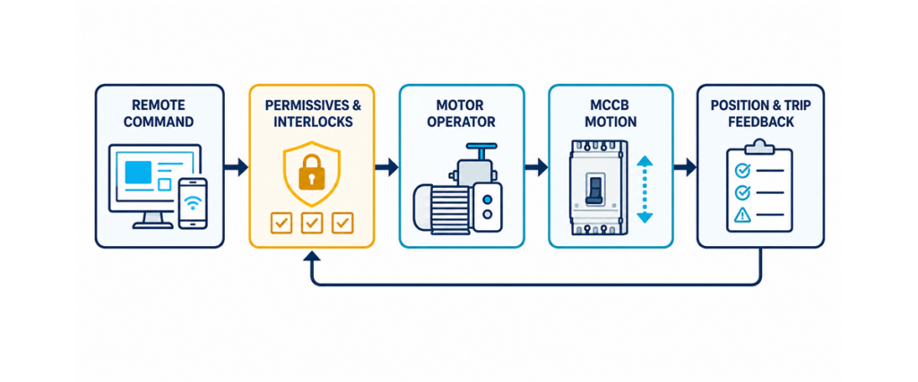
원격 명령, 허가 및 인터로크, 차단기 동작, 위치 및 트립 피드백을 보여주는 MCCB 모터 구동 조작 메커니즘 제어 체인.명령
- 명령은 로컬 푸시버튼, PLC 출력, BMS 릴레이, 절체 제어기 또는 보호 릴레이에서 올 수 있습니다. 메커니즘이 펄스, 유지 신호 또는 별도의 OPEN 및 CLOSE 입력 중 무엇을 기대하는지 정의하십시오. 제어 전압으로부터 배열을 추정하지 마십시오. 명령은 상호 배타적이어야 합니다. 릴레이 중첩이나 소프트웨어 오류로 OPEN과 CLOSE가 동시에 활성화될 수 있다면, 회로는 충돌을 예측 가능하게 해결해야 합니다.
허가
- 명령은 요청이지, 회로에 전원을 공급할 권한이 아닙니다. 투입 허용 조건에는 일반적으로 정상 전원 전압, 활성 잠금 없음, 차단기가 정비 상태가 아님, 대체 전원 개방, 트립 원인 해제, 선택기가 REMOTE 위치에 있음이 포함됩니다. 개방은 일반적으로 허용 조건이 더 적지만, 필요한 로직은 설치자의 판단이 아닌 프로젝트 인과관계 문서에 포함되어야 합니다.
동작
- 허용되면 기구는 제어 전원을 사용하여 차단기를 움직입니다. 전원은 그 과도 수요 동안 전압을 유지해야 합니다. 정지 상태에서 올바르게 측정되는 전원도 모터가 기동할 때 전압이 강하하여 동작이 불완전하게 끝날 수 있습니다. 제조업체가 선언한 동작 시간에 감시 여유를 더해 허용하고, 완료를 강제하기 위해 빠르게 반복 명령을 내리지 마십시오.
피드백
- 명령 후 물리적 상태를 확인하십시오. 위치 접점은 ON 또는 OFF를 나타내며, 별도의 경보 접점은 보호 트립과 명령에 의한 개방을 구별합니다. 명령이 예상 상태 없이 만료되면 개방 실패 또는 투입 실패 경보를 발생시키고 재시도를 차단하십시오. 이는 조용한 고장을 실행 가능한 진단 정보로 바꿉니다.
유지 부하가 아닌 기동 서지에 따라 제어 전원 용량을 산정하십시오
이것은 가장 자주 생략되는 계산이며, 정상 작동하는 패널과 간헐적으로 고장 나는 패널을 구분합니다. 부속 코일은 두 가지 매우 다른 전류를 소비합니다.
- 기동(돌입) VA — 코일이 여자되고 모터가 기동할 때의 짧은 서지입니다. 이는 전원에 필요한 순간 용량과 해당 전원의 다른 모든 장치가 겪게 될 전압 강하를 결정합니다.
- 유지 VA — 여자된 후의 연속 소비입니다. 이는 정상 열 부하를 결정합니다.
유지 부하를 편안하게 감당하지만 기동 중에 전압이 강하하는 전원은 코일을 떨어뜨리거나 아예 흡인되지 못하게 합니다. 장치가 고장 난 것이 아니라, 순간의 수요에 비해 전원 용량이 부족한 것입니다.
피크(기동) 수요:
피크 VA = Σ (기동 VA × 수량)
코일 전압에서의 피크 전류:
I피크 = 피크 VA / V
정상(유지) 수요:
정상 VA = Σ (유지 VA × 수량)
권장 전원 정격:
예시적인 1차 근사 전원 = 피크 VA × 1.25
25 배율은 JUTRION 계산기가 사용하는 예시적 여유이며, IEC 60947-2에서 명시한 보편적 요구 사항이 아닙니다. 전원 제조업체, 제어 변압기 데이터, 프로젝트 표준, 사용률, 온도 또는 동시 동작 연구가 다른 여유를 요구하는 경우 이를 대체하십시오.
여러 부속 장치가 함께 여자될 수 있는 경우 — 모터 조작기가 사이클을 실행하는 동안 저전압 해제 코일이 유지되는 경우 — 해당 기동 수치를 합산하십시오. 단일 장치가 아닌 그 조합이 최악의 경우입니다. JUTRION 차단기 부속 전원 계산기 는 이 방정식을 직접 실행합니다.
| 부속 장치 | 기동 (VA) | 유지 (VA) | 사용 빈도 |
|---|---|---|---|
| 모터 조작기 | Approx. 300–600 | 0 | Draws only during the operating cycle |
| 션트 트립 (MX) | Approx. 100–300 | 0 | 순간적; 트립 시에만 여자됨 |
| 부족전압 릴리스 (MN) | Approx. 200–350 | Approx. 5–10 | Continuously energised |
| 보조 / 경보 접점 | Negligible | Negligible | Volt-free contact |
These are the illustrative default ranges published by the JUTRION calculator, not IEC values or ordered-product ratings. Coil demand varies by series, frame and AC or DC type, so replace every default with the datasheet figure for the device actually ordered. The table is useful for understanding pickup versus holding duty, not for issuing a final transformer or power-supply specification.
Check the Volt Drop Before Choosing a 24 V DC Coil
Low-voltage DC is often specified for compatibility with a PLC rail or a UPS-backed control supply. For a motor operator it deserves a second look: the same power at a lower voltage means proportionally more current, and volt drop rises with it.
For a two-wire DC control circuit:
ΔU = 2 × L × I × ρ / A
Where ΔU is volt drop in V, L is the one-way run in m, I is the operating current in A, ρ is copper resistivity (about 0.0175 Ω·mm²/m at 20 °C, rising with temperature) and A is conductor area in mm². Rearranged for the permissible run:
Lmax = ΔU × A / (2 × I × ρ)
For an illustrative comparison, assume a mechanism with a 450 VA pickup demand and allow a 10% drop. The 450 VA value is a constructed input within the calculator’s typical range, not a JUTRION model rating:
| Coil voltage | Pickup current | Permitted drop | Max. run on 2.5 mm² | Max. run on 6 mm² |
|---|---|---|---|---|
| DC 24 V | 18.8 A | 2.4 V | Approx. 9 m | Approx. 22 m |
| DC 110 V | 4.1 A | 11 V | Approx. 192 m | Approx. 460 m |
| AC 220 V | 2.0 A | 22 V | Approx. 768 m | Approx. 1844 m |
Under these specific assumptions, the 24 V DC option on 2.5 mm² conductor reaches the 10% drop allowance at roughly nine metres. This is not a universal cable-length limit: the result changes directly with the ordered mechanism’s pickup demand, conductor size, temperature, terminal losses, and permitted operating-voltage range. For long control-room runs, compare a larger conductor, a local supply at the breaker, and a higher control voltage.
This is why accessory coils are offered across such a wide voltage range. JUTRION motorised operating mechanisms are available in AC 110 V, AC 220 V and AC 400 V, and in DC 24 V, DC 36 V, DC 110 V and DC 220 V, so the control voltage can be chosen to suit the cable run rather than the cable being sized around a voltage chosen by habit.
A Worked Example: 400 A Feeder with a Remote Motor Operator
The application. A 400 A MCCB feeds a pumping station from a control room about 60 m away. The breaker must be opened, reset and closed remotely. An undervoltage release is fitted so the breaker trips on loss of the control supply.
Step 1 — list what can energise together. The motor operator runs its cycle while the undervoltage release is held in. Both sit on the same control supply, so both count.
Step 2 — define illustrative inputs. Assume a motor operator at 450 VA pickup / 0 holding and an undervoltage release at 275 VA pickup / 7 VA holding. These constructed values sit within the JUTRION calculator’s illustrative ranges; replace them with the ordered accessory datasheets.
Step 3 — peak demand.
Peak VA = (450 × 1) + (275 × 1) = 725 VA
Step 4 — steady demand.
Steady VA = (0 × 1) + (7 × 1) = 7 VA
The ratio is the lesson: the momentary demand is more than a hundred times the continuous one.
Step 5 — size the supply.
Illustrative supply = 725 × 1.25 = 906 VA
Step 6 — check the voltage against the run. At DC 24 V the peak current is 725 / 24 = 30.2 A, and holding a 10 % drop over 60 m would need roughly 26 mm² — impractical for a control circuit. At AC 220 V the peak is 725 / 220 = 3.3 A and 2.5 mm² is comfortable with margin.
Illustrative result: AC 220 V is the more practical option for the assumed 60 m run. A control transformer around 1 kVA and 2.5 mm² conductors are the first-pass result under the stated inputs; final selection requires the transformer’s short-time regulation, protection, installation method, temperature, actual accessory data, and permitted voltage range. At DC 24 V, this example points toward a local supply or a substantially larger conductor.
Automatic Closing Needs Permissives, Interlocks and a Reset Policy
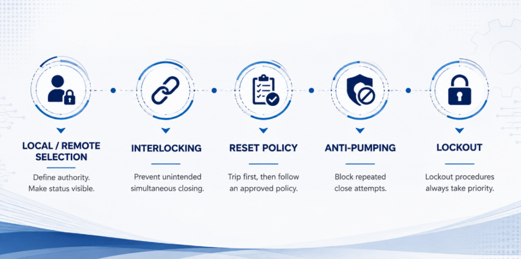
Automatic closing permissives, source interlocking, reset policy, anti-pumping and maintenance lockoutRemote opening is straightforward. Remote closing can energise damaged equipment, restart machinery, parallel sources, or expose people who believed a circuit would stay open. The close path deserves more engineering attention than the motor.
Local/remote selection. A selector defines who has authority. Its state should be visible to the controller, so a blocked command produces a clear “local mode” indication rather than a generic failure alarm.
Source interlocking. Where two breakers select between utility, generator or bus sources, logic must prevent unintended simultaneous closing unless the system is designed to parallel. Mechanical interlocking adds a physical layer, but its compatibility must be verified with the chosen breakers and mechanisms.
Reset and reclose policy. A protective trip should normally block automatic closing until the cause is classified. Some systems permit one supervised reclose for a defined transient; others require investigation after every trip. The motor operator executes the approved policy — it should not create one by default.
Anti-pumping. If a CLOSE command remains present while the breaker trips, the system must not cycle between closing and tripping. The control architecture should block repeated attempts until the command is removed and a new authorised sequence begins.
Maintenance lockout. Software inhibition is not a substitute for an approved lockout procedure. A remote system can issue commands unexpectedly during testing, communication recovery or a software restart.
Apply the Logic to Three Common Architectures
Generator and Source Transfer
Two breakers, each with a motor operator, are switched by a transfer controller so that only one is ever closed. A motor operator is essential because the controller must 닫을 a breaker, not merely trip one.
The controller opens the active source, confirms it is open through position feedback, and only then permits the alternate source to close. Interlocking is mandatory. The control supply must also be available from whichever source is live — a detail easily missed when the control transformer is fed from the utility side alone.
Key distinction: a motor operator supplies motion; it does not by itself make two breakers a transfer switch.
Unattended Site or Remote Substation
A breaker in a rooftop plant room, a pumping station or an unmanned substation is motorised so a trip can be investigated and supply restored without a site visit. The cable run is usually long, which makes the control-voltage decision the governing constraint rather than the mechanism. Fit an alarm contact alongside the position contact so the control system can distinguish a fault trip from a commanded opening before anyone attempts a remote reset.
Load Shedding and Scheduled Switching
An energy-management system opens non-critical feeders when generator capacity or site demand reaches a limit, then restores them in stages to avoid a second demand peak. Each feeder needs a priority, a minimum off time, a close permissive and a failure alarm.
One opening and one closing movement per day totals about 10,950 movements over fifteen years. Confirm how the ordered mechanism defines an operation or cycle before comparing this figure with endurance. Frequent routine switching may belong to a contactor, with the breaker left to provide protection and isolation.
Retrofitting a Motor Operator to a Breaker Already Installed
Most writing on this subject assumes breaker and accessory are specified together. A large share of real enquiries are the opposite: the breaker has been in service for years, the requirement for remote operation appeared later, and the question is whether a mechanism can be added without replacing it.
Some installed MCCBs can accept a retrofit operator without replacing the breaker. Where the approved mechanism mounts on the front, the current path and trip settings may remain unchanged, but the panel must be isolated and the breaker condition checked before installation. Three things decide whether the retrofit is practical:
- Series and frame. The mechanism is matched to the specific breaker, not to its ampere rating. Two 250 A breakers from different series will usually need different mechanisms.
- Front clearance. A motor operator adds depth. Check the distance to the enclosure door and to any escutcheon before ordering.
- Control supply. An existing panel may have no control transformer or DC supply, or one without the capacity calculated above. On retrofits this is more often the real constraint than the mechanism.
Brand is not an automatic barrier. Model-specific adaptation can cover approximately 99% of mainstream breaker designs, with the mounting interface, terminal layout and coil voltage matched to the target breaker. This percentage describes the breadth of an adaptation programme; it does not mean that one universal mechanism fits every MCCB.
Compatibility check: record the breaker manufacturer, series, frame and number of poles, then provide clear nameplate and front-view photographs. These inputs allow the mounting interface and operating travel to be checked before a mechanism is selected.
A serviceable breaker may then gain remote operation without replacement, subject to its condition, available space, required documentation and an approved mechanism match.
Check the Supporting Accessory Options
A complete MCB and MCCB accessory range may include motorised operating mechanisms, shunt trips, undervoltage releases, auxiliary contacts and alarm contacts. The table below compares their control-side functions; mechanical fitment still has to be confirmed against the breaker nameplate.
| 부속 장치 | Control voltage options | 구성 | Rated endurance |
|---|---|---|---|
| Motorised operating mechanism | AC 110 V, AC 220 V, AC 400 V; DC 24 V, DC 36 V, DC 110 V, DC 220 V | Built-in auto/manual selector | 10,000 remote operations |
| Shunt trip (MX / ST) | AC 230 V, AC 400 V; DC 24 V | Instantaneous tripping | 4,000 tripping operations |
| Undervoltage release (MN / UVR) | AC 230 V, AC 400 V; DC 24 V, DC 48 V | Drop-out at 35 %–70 % Un | 4,000 tripping operations |
| 보조 접점 (OF) | Volt-free | 1 NO + 1 NC, or 2 NO + 2 NC | 10,000 electrical cycles |
| Alarm contact (SD) | Volt-free | 1 NO + 1 NC, or 2 NO + 2 NC | 10,000 electrical cycles |
The wide voltage range lets the control supply follow the installation. Inside one switchboard, DC 24 V can integrate conveniently with PLC logic; on a long run, a higher control voltage may reduce conductor demand.
The published portfolio figures list 10,000 remote operations for the mechanism category and 4,000 tripping operations for the trip accessories. Confirm how the ordered model defines and tests an operation before comparing it with the project duty. Use a contactor where frequent routine switching is required.
Avoid the Eight Mistakes That Cause Motor Operator Failures
| Mistake | Consequence | Prevention |
|---|---|---|
| Specifying a shunt trip for “remote control” | Trips remotely, but must be closed by hand at the panel | Confirm first whether remote closing is required |
| Assuming remote close includes reset from TRIPPED | The breaker will not close after a fault trip | State “remote reset after trip” explicitly in the specification |
| Sizing the control supply on holding VA | The mechanism fails to pull in, intermittently | Size on combined pickup demand and apply the documented project margin |
| Choosing DC 24 V for a long run | Volt drop prevents reliable operation; misdiagnosed as a faulty mechanism | Check volt drop at the actual run before fixing the voltage |
| Ignoring simultaneous accessory operation | Supply adequate for one device sags when two energise | Add the pickup VA of everything that can energise together |
| 정격 전류만으로 매칭하는 것 | The accessory cannot be mounted, or fouls the door | Confirm series, frame and clearance from the nameplate |
| Omitting a separate trip/alarm contact | The system cannot tell a fault trip from a commanded opening, and may reclose onto a fault | Fit position and alarm contacts and wire both |
| Leaving the selector in MANUAL after commissioning | Remote commands are silently ignored | Verify and record the selector position at handover |
Diagnose Failures by Following the Control Chain
| Symptom | Likely areas | Evidence to collect | Safe next action |
|---|---|---|---|
| Motor does not run | Missing supply, selector in MANUAL, command absent, permissive open, control fuse | Voltage at supply and command terminals; selector and PLC status | Trace command and permission before replacing anything |
| Motor runs, breaker does not change state | Mechanical mismatch, misalignment, breaker still TRIPPED, incomplete reset | Breaker indication; manual movement; alignment | Isolate control power and inspect the mechanical interface |
| Breaker reaches position but PLC shows failure | Wrong auxiliary contact, NO/NC interpretation, broken feedback wire, timer too short | Contact state at breaker and controller; measured operating time | Correct the feedback logic rather than extending the timer blindly |
| Control voltage collapses during movement | Undersized supply, long run, small conductor, simultaneous loads | Minimum voltage at the mechanism during operation | Correct the supply circuit using model-specific data |
| Works locally, not from the control room | Volt drop over the long run, loose terminal at a marshalling point | Recalculate drop at actual size and length; inspect terminations | Resize the conductor or change the control voltage |
| Breaker repeatedly closes and trips | Fault not cleared, maintained close command, missing anti-pumping logic | Trip indication, command history, protection events | Block reclosing and investigate the protected circuit |
Do not begin diagnosis by bypassing permissives or forcing the handle. Identify first which of the four functions failed — command, permission, motion or feedback. That keeps a control-logic fault from being mistaken for a mechanical failure, and prevents repeated operation against a blocked or tripped breaker.
Record These Parameters Before Selecting a Mechanism
- A photograph of the breaker nameplate — this settles brand, series, frame and rating in one step
- Breaker brand, series and model, if the nameplate is not accessible
- Number of poles and mounting orientation
- Functions required: remote open, remote reset after trip, remote close, or all three
- Control voltage available, AC or DC, and its source
- Cable run from the control supply to the breaker
- Command method: pulse, maintained, or separate OPEN and CLOSE inputs
- Other accessories fitted at the same time
- Feedback contacts required for position and trip cause
- Expected operations per day or per year
- What must happen if the control supply fails
- Enclosure depth and door clearance
- Destination market and the documentation required for the project
What the Technical Submittal Should Confirm
A useful technical submittal should identify the exact mechanism matched to the stated breaker rather than merely repeat the breaker current. Check the control-voltage designation, opening and closing input arrangement, reset capability, pickup power or current, operating time, mechanical endurance, terminal diagram, overall dimensions, and the compatible auxiliary-contact arrangement. It should also state whether the mechanism is a complete front-mounted assembly or requires separate brackets, couplers or wiring accessories.
For a retrofit, request a drawing that shows the mounting interface and added depth. For an automated source-transfer or interlocked feeder application, request the command truth table as well: which inputs are accepted in ON, OFF and TRIPPED states, how long a command must remain present, and what happens when the supply disappears mid-operation. These details turn a claim of compatibility into an interface that a panel builder can review.
If two mechanisms use different pickup values, operating times or reset sequences, they are not directly equivalent even when both carry the same product description. Compare the complete control function and installation requirements, not the actuator rating alone.
자주 묻는 질문
모터 오퍼레이터와 션트 트립의 차이점은 무엇입니까?
전동 조작기는 호환되는 MCCB를 기계적으로 열고, 리셋하고, 닫습니다. 션트 트립은 코일에 전원이 공급되면 차단기를 전기적으로 트립시키며 리셋하거나 닫을 수 없습니다. 자동화 시스템에서는 서로 다른 기능을 위해 둘 다 사용하는 경우가 많습니다.
모터 조작기가 트립 후 차단기를 리셋할 수 있나요?
정합된 메커니즘은 리셋 동작을 수행할 수 있지만, 이는 모델별로 다릅니다. 해당 차단기 모델에 대해 조작기가 원격 리셋을 지원하는지 확인하고, 제어 시스템이 투입 명령을 수락하기 전에 트립 상태를 해제하도록 요구하십시오.
Can I fit a motor operator to a breaker from another manufacturer?
Cross-brand fitting is possible when a mechanism has been adapted and verified for the target breaker. Compatibility cannot be established from current rating alone. Confirm the manufacturer, series, frame, poles, mounting interface and operating travel from the nameplate, dimensional data and front-view photographs.
Can a motor operator be added to a breaker already installed?
Some installed MCCBs can accept a front-mounted operator without replacing the breaker. Confirm the breaker condition, series, frame, handle interface, front clearance, mounting points, control supply, feedback wiring, and required project documentation before approving the retrofit.
Which control voltage should I choose?
Choose it from the cable run, not from habit. Calculate the pickup current at each candidate voltage and check volt drop over the actual distance. Within a switchboard DC 24 V is convenient; over a long run an AC 220 V coil usually gives a far simpler cable.
Does a motorised MCCB close automatically after a fault?
Not safely by default. Automatic closing requires an approved reset policy, a cleared trip condition, healthy permissives, correct interlocking and confirmed feedback. Many installations require manual authorisation after any protective trip.
Final Engineering Check
- Remote closing is genuinely required, not just remote tripping
- Reset from TRIPPED is specified explicitly if the breaker must recover from a fault trip
- Breaker series, frame and mounting confirmed from the nameplate
- Pickup and holding VA taken from the datasheet, not assumed
- Combined pickup demand calculated for everything that can energise together
- Control supply sized for combined pickup demand, with the margin required by the selected supply, project and installation conditions
- Control voltage chosen after checking volt drop at the actual run
- Behaviour on loss of control supply decided, with an undervoltage release if required
- Position and trip/alarm contacts specified and wired
- Close permissives, interlocking and anti-pumping defined in the control logic
- Expected operations per year checked against rated endurance
- Front clearance verified and the selector position recorded at commissioning
Specify the Control Chain Before the Mechanism
The mechanism is the straightforward part. What determines whether the installation works is everything around it: whether the control supply holds its voltage through a surge many times the steady load, whether the chosen coil voltage survives the distance, and whether the logic can tell a tripped breaker from an open one.
The practical order is: confirm remote closing is required, identify the breaker from its nameplate, decide which motions are needed including reset, choose the control voltage from the cable run, size the supply on combined pickup demand, then settle feedback, interlocking and endurance.
For further selection context, see the guide to circuit breaker accessories. To check an exact mechanism match, provide the breaker nameplate, front-view photograph and project requirements so the complete assembly can be reviewed before installation.
Technical References and Data Boundaries
The sources serve different purposes. IEC 60947-2:2024 provides the product-standard framework for low-voltage circuit-breakers; it is not cited as the source of the 1.25 illustrative supply allowance, typical accessory VA ranges, JUTRION control-voltage options, endurance figures, or 99% adaptation coverage. Those values come from the current JUTRION accessories page and breaker accessory power calculator. Exact electrical demand, timing, operating-voltage limits, and compatibility must come from the ordered accessory documentation.
- IEC 60947-2:2024 — Low-voltage switchgear and controlgear — Part 2: Circuit-breakers (sixth edition, September 2024; supersedes the 2016 fifth edition and its Amendment 1:2019). UL 489 applies to moulded-case circuit breakers in North American markets.
