

ໃນສະພາບແວດລ້ອມວິສະວະກຳຕົວຈິງ, ໄຟດັບບໍ່ເຄີຍເປັນພຽງ “ຄວາມມືດບໍ່ເທົ່າໃດນາທີ.” ສຳລັບສູນຂໍ້ມູນ ຫຼື ໂຮງໝໍ, ແມ່ນແຕ່ໄຟດັບບໍ່ເທົ່າໃດວິນາທີກໍອາດໝາຍເຖິງໄພພິບັດ. ໃນສາຍການຜະລິດອຸດສາຫະກຳ, ແຮງດັນຕົກກະທັນຫັນອາດເຮັດໃຫ້ວັດຖຸດິບທັງຊຸດຖືກປະຖິ້ມ ແລະ ນຳໄປສູ່ຂະບວນການເລີ່ມອຸປະກອນໃໝ່ທີ່ຍາວນານ. ແມ່ນແຕ່ໃນອາຄານພານິດຊັ້ນສູງ, ຄວາມລົ້ມເຫຼວຂອງລະບົບປ້ອງກັນອັກຄີໄພ ແລະ ລະບົບຮັກສາຄວາມປອດໄພກໍເປັນຄວາມສ່ຽງທີ່ຍອມຮັບບໍ່ໄດ້.
ສະຫຼັບສົ່ງກຳລັງໄຟຟ້າອັດຕະໂນມັດ (ATS) ແມ່ນ “ແນວປ້ອງກັນສຸດທ້າຍ” ໃນສາຍຊີວິດການສະໜອງໄຟຟ້ານີ້. ໃນຖານະເປັນສູນກາງຫຼັກຂອງລະບົບໄຟຟ້າສອງແຫຼ່ງ, ເມື່ອໄຟຟ້າຫຼັກປະສົບກັບແຮງດັນຕໍ່າ, ໄຟດັບ, ຫຼື ແມ່ນແຕ່ເຟສຂາດ, ATS ຕ້ອງຕັດສິນໃຈຢ່າງແມ່ນຍຳພາຍໃນເວລາອັນສັ້ນທີ່ສຸດ, ສົ່ງພາລະສຳຄັນໄປຍັງແຫຼ່ງໄຟຟ້າສຳຮອງຢ່າງປອດໄພ, ແລະ ສະຫຼັບກັບຄືນຢ່າງລຽບງ່າຍພຽງແຕ່ຫຼັງຈາກໄຟຟ້າຫຼັກກັບຄືນສູ່ສະພາບປົກກະຕິຢ່າງສົມບູນແລ້ວເທົ່ານັ້ນ.
ຫຼາຍໂຄງການເຮັດຜິດພາດຮ້າຍແຮງໃນລະຫວ່າງການຈັດຊື້: ພວກເຂົາຄິດວ່າ ATS ເປັນພຽງ “ສະຫຼັບໃຫຍ່” ທຳມະດາ, ແລະ ວ່າການເລືອກກະແສໄຟຟ້າທີ່ກຳນົດໃຫ້ຖືກຕ້ອງກໍພຽງພໍແລ້ວ. ໃນຄວາມເປັນຈິງ, ມັນແມ່ນ “ຜູ້ຄວບຄຸມການຈະລາຈອນ” ລະຫວ່າງສອງແຫຼ່ງໄຟຟ້າ. ຈາກຄວາມລ່າຊ້າໃນການສ້າງແຮງດັນຂອງເຄື່ອງປັ່ນໄຟ, ເຖິງຍຸດທະສາດການສະຫຼັບນິວຕຣອນ (ການເລືອກຂົ້ວ), ເຖິງການປະສານງານການປ້ອງກັນວົງຈອນສັ້ນກັບເບຣກເກີທາງຕົ້ນນ້ຳ ແລະ ປາຍນ້ຳ, ການຕັດສິນໃຈຜິດພາດໃນລາຍລະອຽດເຫຼົ່ານີ້ອາດເຮັດໃຫ້ລະບົບທັງໝົດລົ້ມເຫຼວໃນຊ່ວງເວລາສຳຄັນ.
ຖ້າທ່ານຍັງຢູ່ໃນຂັ້ນຕອນການປະເມີນອຸປະກອນຂອງໂຄງການ, ແນະນຳໃຫ້ທ່ານເບິ່ງ [ພາກສ່ວນຜະລິດຕະພັນຫຼັກຂອງສະຫຼັບສົ່ງກຳລັງໄຟຟ້າອັດຕະໂນມັດ (ATS)],ເພື່ອໃຫ້ທ່ານສາມາດລະບຸສະຖາປັດຕະຍະກຳພື້ນຖານທີ່ເໝາະສົມທີ່ສຸດສຳລັບລະບົບຂອງທ່ານໄດ້ຢ່າງວ່ອງໄວ.
ໃນໂຄງການສາກົນ, ການເລືອກ ATS ບໍ່ຄວນອີງໃສ່ພຽງແຕ່ລາຍການສິນຄ້າເທົ່ານັ້ນ. ຄວນປະເມີນຕາມມາດຕະຖານ ແລະ ລະຫັດທີ່ກ່ຽວຂ້ອງທີ່ຢູ່ເບື້ອງຫຼັງຜະລິດຕະພັນນຳອີກ, ລວມທັງ IEC 60947-6-1 ສຳລັບອຸປະກອນສະຫຼັບຖ່າຍໂອນທີ່ໃຊ້ເພື່ອຮັບປະກັນຄວາມຕໍ່ເນື່ອງຂອງການຈ່າຍໄຟ, NFPA 70 (NEC) ສຳລັບການອອກແບບ ແລະ ການຕິດຕັ້ງໄຟຟ້າທີ່ປອດໄພໃນໂຄງການຂອງສະຫະລັດ, ແລະ NFPA 110 ສຳລັບລະບົບໄຟຟ້າສຸກເສີນ ແລະ ສຳຮອງໃນອາຄານ ແລະ ສະຖານທີ່ຕ່າງໆ.
ສະຫຼັບຖ່າຍໂອນອັດຕະໂນມັດ (ATS) ແມ່ນຫຍັງ?
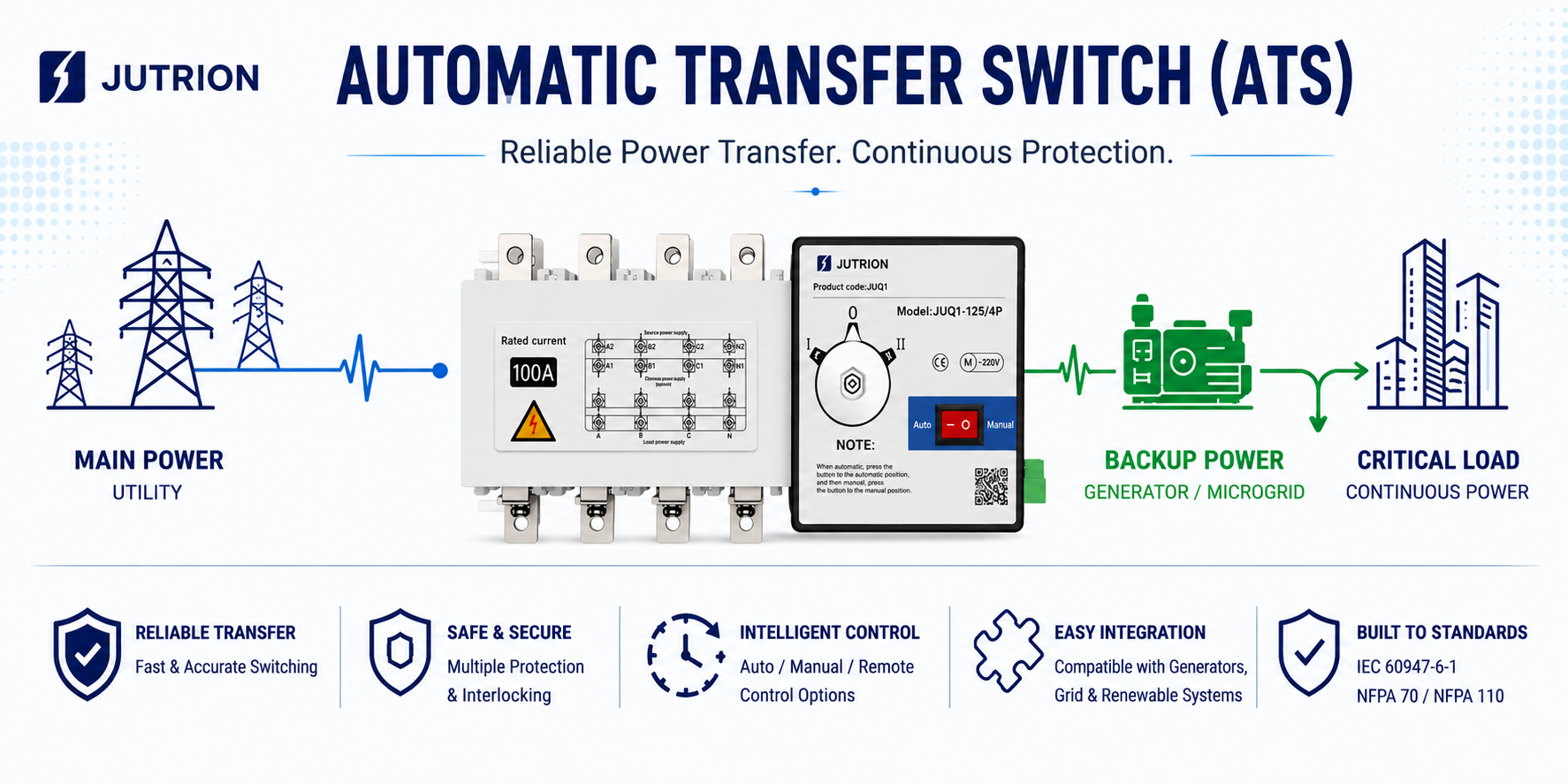
ສະຫຼັບຖ່າຍໂອນອັດຕະໂນມັດ (ATS) ແມ່ນອຸປະກອນສະຫຼັບທີ່ສຳຄັນທີ່ໃຊ້ໃນລະບົບຈ່າຍໄຟສອງແຫຼ່ງ. ປົກກະຕິແລ້ວມັນຖືກຕິດຕັ້ງລະຫວ່າງແຫຼ່ງໄຟຫຼັກ ແລະ ແຫຼ່ງໄຟສຳຮອງ, ເຮັດໃຫ້ສາມາດຖ່າຍໂອນໂຫຼດຈາກແຫຼ່ງໜຶ່ງໄປຍັງອີກແຫຼ່ງໜຶ່ງໄດ້ເມື່ອຈຳເປັນ. ການປະສົມແຫຼ່ງທີ່ພົບເລື້ອຍລວມມີ ໄຟຫຼັກ-ເຄື່ອງປັ່ນໄຟ, ໄຟຫຼັກ-ໄຟຫຼັກ, ແລະ ໄຟຫຼັກ-ບ່ອນເກັບພະລັງງານ ຫຼື ຜົນຜະລິດຂອງອິນເວີດເຕີ.
ບໍ່ຄືກັບເບຣກເກີທຳມະດາ, ຈຸດປະສົງຫຼັກຂອງ ATS ບໍ່ແມ່ນການຕັດກະແສລັດວົງຈອນໂດຍກົງ. ໜ້າທີ່ຫຼັກຂອງມັນແມ່ນຮັບປະກັນການຖ່າຍໂອນທີ່ເຊື່ອຖືໄດ້, ຄວບຄຸມໄດ້ ແລະ ມີການລັອກກັນຢ່າງຖືກຕ້ອງລະຫວ່າງສອງແຫຼ່ງໄຟທີ່ມີຢູ່. ດ້ວຍເຫດນີ້, ການອອກແບບ ATS ມັກຈະເນັ້ນໃສ່ກົນໄກການສະຫຼັບ, ລະບົບຄວບຄຸມ, ການຕິດຕາມແຫຼ່ງໄຟ, ການລັອກກັນທາງກົນ ແລະ ໄຟຟ້າ, ແລະ ຄວາມຕໍ່ເນື່ອງຂອງລະບົບຈ່າຍໄຟໂດຍລວມ.
ຈາກມຸມມອງທາງວິສະວະກຳ, ATS ໂດຍພື້ນຖານແລ້ວແມ່ນອຸປະກອນທີ່ໃຊ້ເພື່ອຮັກສາຄວາມຕໍ່ເນື່ອງຂອງການຈ່າຍໄຟ. IEC ຍັງໄດ້ກຳນົດກອບມາດຕະຖານທີ່ຊັດເຈນສຳລັບອຸປະກອນສະຫຼັບຖ່າຍໂອນ ແລະ ອຸປະກອນສະຫຼັບຖ່າຍໂອນອັດຕະໂນມັດ. ດັ່ງນັ້ນ, ໃນໂຄງການສົ່ງອອກ, ໂຄງການ EPC, ແລະ ການນຳໃຊ້ວິສະວະກຳຂ້າມຊາຍແດນ, ມາດຕະຖານທີ່ກ່ຽວຂ້ອງ, ເອກະສານການທົດສອບ, ແລະ ຂີດຈຳກັດການເຮັດວຽກຂອງ ATS ລ້ວນແຕ່ເປັນຂໍ້ພິຈາລະນາທີ່ສຳຄັນ.
ວິທີທີ່ ATS ເຮັດວຽກລະຫວ່າງແຫຼ່ງໄຟຟ້າຫຼັກ ແລະ ແຫຼ່ງໄຟຟ້າສຳຮອງ
ຂະບວນການເຮັດວຽກຂອງ ATS ລະຫວ່າງແຫຼ່ງໄຟຟ້າຫຼັກ ແລະ ແຫຼ່ງໄຟຟ້າສຳຮອງ ສ່ວນໃຫຍ່ປະກອບມີ ການຕິດຕາມແບບທັນສະໄໝ, ການຕັດສິນຄວາມຜິດປົກກະຕິ, ການສັບປ່ຽນທີ່ເຊື່ອຖືໄດ້, ແລະ ການສັບປ່ຽນກັບຄືນອັດຕະໂນມັດ. ຂະບວນການທັງໝົດເປັນແບບອັດຕະໂນມັດເຕັມຮູບແບບ ແລະ ມີການລັອກກັນທາງຄວາມປອດໄພ, ແລະ ສາມາດແບ່ງອອກເປັນສີ່ຂັ້ນຕອນສະເພາະ:
ຂັ້ນຕອນການເຮັດວຽກປົກກະຕິ (ແຫຼ່ງໄຟຟ້າຫຼັກເຮັດວຽກຢູ່)
ຕາມຄ່າເລີ່ມຕົ້ນ, ATS ຈ່າຍໄຟໃຫ້ໂຫຼດຈາກ ແຫຼ່ງໄຟຟ້າຫຼັກ (ໄຟຟ້າສາທາລະນູປະໂພກ), ໃນຂະນະທີ່ຕົວຄວບຄຸມຕິດຕາມພາລາມິເຕີຫຼັກຂອງແຫຼ່ງໄຟຟ້າຫຼັກຢ່າງຕໍ່ເນື່ອງຕະຫຼອດ 24/7 ເຊັ່ນ ແຮງດັນ, ຄວາມຖີ່, ແລະ ສະພາບເຟສ. ແຫຼ່ງໄຟຟ້າສຳຮອງຢູ່ໃນໂໝດສະແຕນບາຍຮ້ອນ, ແລະ ອຸປະກອນສັບປ່ຽນຫຼັກ ແລະ ສຳຮອງຖືກລັອກກັນທາງກົນຈັກ ແລະ/ຫຼື ທາງໄຟຟ້າ ເພື່ອ ປ້ອງກັນການປິດວົງຈອນພ້ອມກັນຢ່າງເຂັ້ມງວດ, ດັ່ງນັ້ນຈຶ່ງຫຼີກລ່ຽງການລັດວົງຈອນລະຫວ່າງສອງແຫຼ່ງໄຟຟ້າ.
ຂັ້ນຕອນໄຟຟ້າຫຼັກຂັດຂ້ອງ (ກະຕຸ້ນການສັບປ່ຽນ)
ເມື່ອແຫຼ່ງໄຟຟ້າຫຼັກເກີດໄຟດັບ, ແຮງດັນຕໍ່າ, ແຮງດັນສູງ, ເຟສຂາດ, ຫຼື ຄວາມຖີ່ຜິດປົກກະຕິ, ATS ຈະນຳໃຊ້ ເວລາໜ່ວງຢືນຢັນຄວາມຜິດປົກກະຕິທີ່ກຳນົດຄ່າໄດ້ (ປົກກະຕິ 0.5–5 ວິນາທີ) ເພື່ອກັ່ນຕອງການເໜັງຕີງຊົ່ວຄາວ. ເມື່ອຢືນຢັນວ່າຄວາມຜິດປົກກະຕິເປັນຈິງແລ້ວ, ລຳດັບຕໍ່ໄປນີ້ຈະເກີດຂຶ້ນ:
- ຕົວຄວບຄຸມສົ່ງຄຳສັ່ງເພື່ອຂັບເຄື່ອນກົນໄກໃຫ້ ເປີດສະວິດໄຟຟ້າຫຼັກ;
- ຫຼັງຈາກສະວິດໄຟຟ້າຫຼັກຖືກເປີດອອກໝົດແລ້ວ, ສະວິດໄຟຟ້າສຳຮອງຈຶ່ງຖືກປິດ. ໃນບາງການນຳໃຊ້, ລະບົບຕ້ອງລໍຖ້າຈົນກວ່າແຫຼ່ງໄຟຟ້າສຳຮອງຈະສະຖຽນເສຍກ່ອນ ເຊັ່ນ ເມື່ອເຄື່ອງປັ່ນໄຟໄດ້ເລີ່ມເຮັດວຽກ ແລະ ບັນລຸແຮງດັນ ແລະ ຄວາມຖີ່ທີ່ກຳນົດແລ້ວ;
- ຈາກນັ້ນໂຫຼດຈຶ່ງຖືກສັບປ່ຽນໄປຫາແຫຼ່ງໄຟຟ້າສຳຮອງ. ຂະບວນການທັງໝົດປົກກະຕິຈະສຳເລັດພາຍໃນມິນລິວິນາທີ, ດັ່ງນັ້ນໂຫຼດສຳຄັນຈຶ່ງມີການຂັດຈັງຫວະໜ້ອຍຫຼາຍຈົນເກືອບບໍ່ສັງເກດເຫັນ.
ຂັ້ນຕອນການຈ່າຍໄຟສຳຮອງ
ATS ສືບຕໍ່ຕິດຕາມສະຖານະການຟື້ນຕົວຂອງແຫຼ່ງໄຟຟ້າຫຼັກ ໃນຂະນະທີ່ຮັກສາການຈ່າຍໄຟທີ່ສະຖຽນຈາກແຫຼ່ງສຳຮອງໃຫ້ແກ່ໂຫຼດ. ບາງລຸ້ນຍັງມີການຕິດຕາມຄວາມຜິດປົກກະຕິຂອງແຫຼ່ງໄຟຟ້າສຳຮອງ ເຊິ່ງຊ່ວຍຫຼຸດຄວາມສ່ຽງທີ່ທັງສອງແຫຼ່ງໄຟຟ້າຈະຂັດຂ້ອງພ້ອມກັນ.
ຂັ້ນຕອນການຟື້ນຕົວຂອງໄຟຟ້າຫຼັກ (ການສັບປ່ຽນກັບຄືນອັດຕະໂນມັດ)
ເມື່ອແຮງດັນ ແລະ ຄວາມຖີ່ຂອງແຫຼ່ງໄຟຟ້າຫຼັກກັບຄືນສູ່ຊ່ວງທີ່ຍອມຮັບໄດ້ ແລະ ຄົງທີ່ເປັນເວລາໃດໜຶ່ງ (ກຳນົດຄ່າໄດ້ ເຊັ່ນ 1–30 ນາທີ), ATS ຈະດຳເນີນການ ສັບປ່ຽນກັບຄືນຈາກໄຟສຳຮອງໄປຫາໄຟຫຼັກ:
- ມັນຈະເປີດສະວິດໄຟຟ້າສຳຮອງກ່ອນ, ແລ້ວຈຶ່ງປິດສະວິດໄຟຟ້າຫຼັກ;
- ໂຫຼດຖືກສັບປ່ຽນກັບຄືນໄປຫາແຫຼ່ງໄຟຟ້າຫຼັກ, ໃນຂະນະທີ່ແຫຼ່ງສຳຮອງກັບຄືນສູ່
ການອອກແບບຄວາມປອດໄພຫຼັກ: ATS ໃຊ້ກົນໄກລັອກກັນທາງກົນຈັກ ແລະ/ຫຼື ທາງໄຟຟ້າ ເພື່ອຮັບປະກັນວ່າສະວິດໄຟຟ້າຫຼັກ ແລະ ສະວິດໄຟຟ້າສຳຮອງຈະບໍ່ສາມາດປິດພ້ອມກັນໄດ້ໃນທຸກກໍລະນີ, ປ້ອງກັນຄວາມສ່ຽງທີ່ຮ້າຍແຮງເຊັ່ນ ກະແສໄຟຟ້າໝູນວຽນ ແລະ ການລັດວົງຈອນໄດ້ຢ່າງສິ້ນເຊີງ. ນີ້ກໍ່ແມ່ນຄວາມແຕກຕ່າງພື້ນຖານທີ່ສຸດລະຫວ່າງ ATS ແລະ ການຈັດວາງສະວິດຄູ່ແບບທຳມະດາ.
ອົງປະກອບຫຼັກຂອງສະວິດສັບປ່ຽນອັດຕະໂນມັດ (ATS)
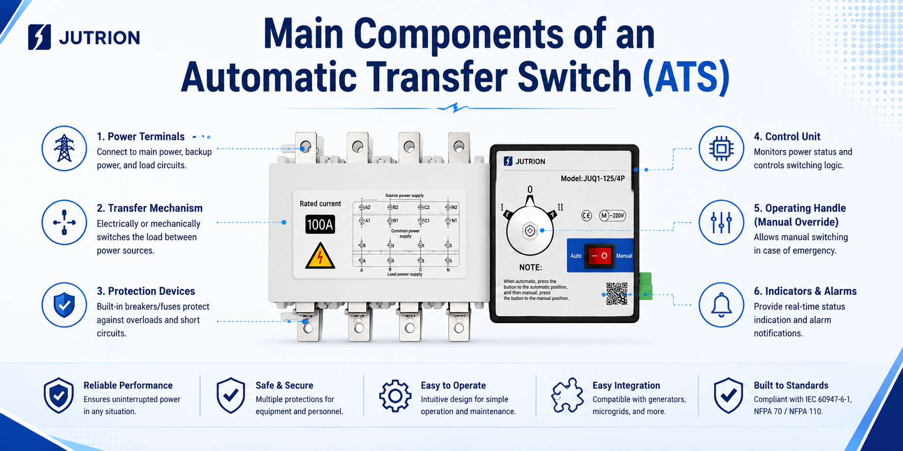
ATS ບໍ່ແມ່ນອຸປະກອນສັບປ່ຽນດ່ຽວ, ແຕ່ເປັນລະບົບຄົບຊຸດທີ່ປະສົມປະສານການຕິດຕາມ, ການຄວບຄຸມ, ການດຳເນີນງານ, ແລະ ການປ້ອງກັນຄວາມປອດໄພ. ອົງປະກອບຫຼັກຂອງມັນແບ່ງອອກເປັນສີ່ໂມດູນໃຫຍ່ ເຊິ່ງຮ່ວມກັນເຮັດໃຫ້ຂະບວນການທັງໝົດຂອງການຕິດຕາມສະຖານະແຫຼ່ງໄຟຟ້າ, ການກວດຈັບຄວາມຜິດປົກກະຕິ, ການສັບປ່ຽນທີ່ປອດໄພ, ແລະ ການສັບປ່ຽນກັບຄືນອັດຕະໂນມັດສຳເລັດໄດ້ ດັ່ງນີ້:
ຕົວສັບປ່ຽນໄຟຟ້າຄູ່ (ກົນໄກຂັບເຄື່ອນ)
ນີ້ແມ່ນ ໜ່ວຍປະຕິບັດການຫຼັກ ຂອງ ATS, ຮັບຜິດຊອບການຖ່າຍໂອນທາງກາຍະພາບລະຫວ່າງແຫຼ່ງໄຟຟ້າຫຼັກ ແລະ ແຫຼ່ງໄຟຟ້າສຳຮອງ. ໂດຍທົ່ວໄປແລ້ວມັນແບ່ງອອກເປັນສອງຮູບແບບຫຼັກ:
- ATS ຊັ້ນ PC ແບບປະສົມປະສານ: ເປັນສະຫຼັບຖ່າຍໂອນແບບປະສົມປະສານດ່ຽວທີ່ມີໂຄງສ້າງກົນໄກລັອກກັນແບບສະເພາະ, ຖືກອອກແບບມາເພື່ອໃຫ້ເຮັດວຽກແບບ “ຕັດກ່ອນຕໍ່”. ມັນສາມາດທົນຕໍ່ກະແສລັດວົງຈອນທີ່ສູງພໍສົມຄວນ ແລະ ຖືກນຳໃຊ້ຢ່າງກວ້າງຂວາງໃນງານທີ່ມີໂຫຼດສຳຄັນ.
- CB Class ATS: ປະກອບດ້ວຍເບຣກເກີສອງໂຕ (ຫຼື ສະຫຼັບຕັດຕອນ) ພ້ອມກັບກົນໄກລັອກກັນແບບກົນຈັກ ແລະ/ຫຼື ໄຟຟ້າ. ມັນໃຫ້ທັງໜ້າທີ່ປ້ອງກັນ ແລະ ຖ່າຍໂອນ, ປົກກະຕິແລ້ວມີລາຄາຖືກກວ່າ, ແລະ ມັກໃຊ້ສຳລັບໂຫຼດທີ່ສຳຄັນທົ່ວໄປ.
ໂຕຄວບຄຸມອັດສະລິຍະ (ສະໝອງຄວບຄຸມ)
ນີ້ແມ່ນ “ສູນກາງການຕັດສິນໃຈ” ຂອງ ATS, ຮັບຜິດຊອບການຕິດຕາມສະຖານະໄຟຟ້າ ແລະ ການຄວບຄຸມລຳດັບການຖ່າຍໂອນ:
- ການຕິດຕາມແບບທັນສະໄໝຂອງພາລາມິເຕີຂອງແຫຼ່ງຈ່າຍໄຟທັງສອງ ເຊັ່ນ ແຮງດັນ, ຄວາມຖີ່, ເຟສຂາດ, ແຮງດັນເກີນ, ແລະ ແຮງດັນຕໍ່າ;
- ການປະຕິບັດລຳດັບເຊັ່ນ ການຢືນຢັນການໜ່ວງເວລາ (ເພື່ອປ້ອງກັນການເຮັດວຽກຜິດພາດ), ການຖ່າຍໂອນເມື່ອເກີດຄວາມຜິດປົກກະຕິ, ການຖ່າຍໂອນກັບຈາກແຫຼ່ງສຳຮອງໄປຫາແຫຼ່ງຫຼັກ, ແລະ ການປະສານງານການເລີ່ມ/ຢຸດເຄື່ອງປັ່ນໄຟ;
- ການໃຫ້ຟັງຊັນຕ່າງໆ ເຊັ່ນ ການຄວບຄຸມໃນທ້ອງຖິ່ນ/ທາງໄກ, ການສະແດງສະຖານະ, ການແຈ້ງເຕືອນຄວາມຜິດປົກກະຕິ, ແລະ ອິນເຕີເຟດການສື່ສານ (ເຊັ່ນ Modbus).
ກົນໄກຂັບເຄື່ອນ ແລະ ລັອກກັນ (ແກນຄວາມປອດໄພ)
- ກົນໄກຂັບເຄື່ອນ: ອາດຈະເປັນແບບມໍເຕີ, ແມ່ເຫຼັກໄຟຟ້າ, ຫຼື ແບບສະສົມພະລັງງານສະປິງ, ໃຫ້ແຮງສະຫຼັບສຳລັບໂຕສະຫຼັບ ແລະ ຮັບປະກັນການເຮັດວຽກທີ່ໜ້າເຊື່ອຖື;
- ກົນໄກລັອກກັນ: ໃຊ້ທັງການລັອກກັນແບບກົນຈັກ ແລະ ໄຟຟ້າ ເພື່ອປ້ອງກັນຢ່າງເຂັ້ມງວດບໍ່ໃຫ້ແຫຼ່ງຈ່າຍໄຟຫຼັກ ແລະ ສຳຮອງຕໍ່ວົງຈອນພ້ອມກັນ, ຫຼີກລ່ຽງອຸບັດຕິເຫດລັດວົງຈອນ ແລະ ກະແສໄຫຼວຽນລະຫວ່າງສອງແຫຼ່ງໄດ້ຢ່າງສິ້ນເຊີງ. ນີ້ແມ່ນການອອກແບບຄວາມປອດໄພຫຼັກທີ່ແຍກ ATS ອອກຈາກການຈັດວາງສະຫຼັບຄູ່ແບບທຳມະດາ.
ອົງປະກອບເສີມ ແລະ ສະໜັບສະໜູນ
- ໜ່ວຍເກັບຕົວຢ່າງໄຟຟ້າ: ສະໜອງສັນຍານແຮງດັນ ແລະ ກະແສໄຟຟ້າຈາກສອງແຫຼ່ງຈ່າຍໄຟໃຫ້ກັບຕົວຄວບຄຸມ
- ໜ້າສຳພັດສະຖານະປ້ອນກັບ: ປ້ອນກັບຕຳແໜ່ງເປີດ/ປິດຂອງສະວິດ ແລະ ສະຖານະຂໍ້ຜິດພາດໃຫ້ກັບລະບົບພາຍນອກ
- ອິນເຕີເຟດຄວບຄຸມເຄື່ອງປັ່ນໄຟ: ບາງໜ່ວຍ ATS ສາມາດສົ່ງສັນຍານອອກໂດຍກົງເພື່ອຄວບຄຸມການເລີ່ມ ແລະ ຢຸດຂອງເຄື່ອງປັ່ນໄຟ ເຮັດໃຫ້ເຄື່ອງປັ່ນໄຟເລີ່ມເຮັດວຽກອັດຕະໂນມັດ ແລະ ຈ່າຍໄຟເມື່ອໄຟຫຼັກຂັດຂ້ອງ;
- ແຜງຄວບຄຸມ / ໜ້າຈໍສະແດງຜົນ: ໃຊ້ສຳລັບການຕັ້ງຄ່າພາລາມິເຕີ, ການຄວບຄຸມການໂອນຍ້າຍແບບຄູ່ມື/ອັດຕະໂນມັດ ແລະ ການສະແດງສະຖານະການເຮັດວຽກ.
ໝາຍເຫດເພີ່ມເຕີມ:
ຄວາມແຕກຕ່າງຂອງອົງປະກອບຫຼັກຂອງ ATS ປະເພດຕ່າງໆ ໂດຍພື້ນຖານແລ້ວແມ່ນຮູບແບບການຈັດຕັ້ງປະຕິບັດທີ່ແຕກຕ່າງກັນພາຍໃຕ້ມາດຕະຖານ IEC. ຕົວຢ່າງ, ຄວາມແຕກຕ່າງລະຫວ່າງ ATS ຊັ້ນ PC ແລະ ATS ຊັ້ນ CB ສ່ວນໃຫຍ່ແມ່ນສະທ້ອນໃຫ້ເຫັນໃນການອອກແບບໂຄງສ້າງຂອງຕົວສະວິດ ແລະ ລະດັບຄວາມສາມາດໃນການປ້ອງກັນ, ໃນຂະນະທີ່ເຫດຜົນການອອກແບບຂອງໂມດູນຄວາມປອດໄພຫຼັກ ເຊັ່ນ ຕົວຄວບຄຸມ ແລະ ກົນໄກລັອກກັນ ທັງໝົດຕ້ອງປະຕິບັດຕາມຂໍ້ກຳນົດບັງຄັບຂອງມາດຕະຖານທີ່ກ່ຽວຂ້ອງ.
ລາຍການກວດສອບການເລືອກ ATS ແບບດ່ວນ
✅ ຢືນຢັນປະເພດໂຫຼດ ແລະ ສະຖານະການນຳໃຊ້ແລ້ວ
✅ ກະແສໄຟຟ້າທີ່ກຳນົດ ແລະ ຂະໜາດເຟຣມຕອບສະໜອງຄວາມຕ້ອງການດ້ານໂຫຼດ ແລະ ການລັດວົງຈອນ
✅ ຈຳນວນຂົ້ວ (3P/4P) ກົງກັບການກຳນົດຄ່າຂອງລະບົບ
✅ ປະເພດ ATS (ຊັ້ນ PC / ຊັ້ນ CB) ກົງກັບລະດັບຄວາມໜ້າເຊື່ອຖືຂອງໂຫຼດທີ່ຕ້ອງການ
✅ ຮູບແບບການຄວບຄຸມ ແລະ ພາລາມິເຕີການໜ່ວງເວລາສາມາດປັບໄດ້ຕາມເງື່ອນໄຂຂອງສະຖານທີ່
✅ ຟັງຊັນເພີ່ມເຕີມ (ການລັອກກັນ / ການສື່ສານ / ບາຍພາດ) ຖືກກຳນົດຄ່າຕາມຄວາມຕ້ອງການ
✅ ເຫດຜົນການປະສານງານກັບອຸປະກອນປ້ອງກັນດ້ານເທິງ ແລະ ລຸ່ມ, ເຄື່ອງປັ່ນໄຟ ແລະ ລະບົບປ້ອງກັນອັກຄີໄພຖືກກຳນົດຢ່າງຊັດເຈນ
ເລີ່ມຈາກການນຳໃຊ້: ກຳນົດລະດັບໂຫຼດ ແລະ ຄວາມຕ້ອງການຂອງໂຄງການກ່ອນ
ຢືນຢັນພາລາມິເຕີຫຼັກ: ໃຫ້ຄວາມສຳຄັນກັບຕົວຊີ້ວັດຫຼັກກ່ອນ
ກະແສໄຟຟ້າທີ່ກຳນົດ ແລະ ຂະໜາດກອບ
- ກະແສໄຟຟ້າທີ່ກຳນົດ (Ie): ຄວນຈະຢ່າງໜ້ອຍ 25 ເທົ່າ ຂອງກະແສໂຫຼດທີ່ຄຳນວນໄດ້, ໂດຍຄຳນຶງເຖິງກະແສເລີ່ມຕົ້ນ ແລະ ຂອບການເຮັດວຽກໄລຍະຍາວ. ຕົວຢ່າງ, ຖ້າກະແສໂຫຼດແມ່ນ 160A, ຄວນເລືອກ ATS ຂະໜາດ 200A ຫຼື 250A.
- ຂະໜາດເຟຣມ: ຄວນເລືອກຕາມກະແສລັດວົງຈອນຂອງລະບົບ ແລະ ຕ້ອງຕອບສະໜອງຄວາມຕ້ອງການສຳລັບກະແສທົນທານລັດວົງຈອນໄລຍະສັ້ນທີ່ກຳນົດ (ອິກຊີວ), ເພື່ອຫຼີກລ່ຽງການເຜົາໄໝ້ພາຍໃຕ້ສະພາບຄວາມຜິດປົກກະຕິ.
ການເລືອກຂົ້ວ (P)
- ATS 3P: ເໝາະສຳລັບລະບົບສາມເຟດສາມສາຍ, ບ່ອນທີ່ສາຍນິວຕຣອນບໍ່ເຂົ້າຮ່ວມໃນການສັບປ່ຽນ. ໃຊ້ໄດ້ກັບລະບົບ TN/IT ແລະ ໂດຍທົ່ວໄປມີລາຄາຖືກກວ່າ.
- ATS 4P: ເໝາະສຳລັບລະບົບສາມເຟດສີ່ສາຍ, ບ່ອນທີ່ສາຍນິວຕຣອນຖືກສັບປ່ຽນພ້ອມກັນ. ໃຊ້ໄດ້ກັບສະຖານະການທີ່ກ່ຽວຂ້ອງກັບການເຄື່ອນຍ້າຍຂອງນິວຕຣອນ, ຄວາມຜິດປົກກະຕິຮາໂມນິກຮຸນແຮງ, ຫຼື ນິວຕຣອນທີ່ບໍ່ໃຊ້ຮ່ວມກັນລະຫວ່າງສອງແຫຼ່ງໄຟຟ້າ (ເຊັ່ນ ໂຮງໝໍ ແລະ ສູນຂໍ້ມູນ), ຊ່ວຍຫຼີກລ່ຽງກະແສໝູນວຽນຂອງນິວຕຣອນ.
ການເລືອກປະເພດ: ຊັ້ນ PC ທຽບກັບ ຊັ້ນ CB (ຄວາມແຕກຕ່າງຫຼັກ)
| ມິຕິ | PC Class ATS | CB Class ATS |
| Core structure | Integrated transfer switch with dedicated mechanical interlocking | Two circuit breakers with interlocking mechanism |
| Protection function | Transfer function only, without short-circuit or overload protection | Built-in circuit breaker protection, capable of short-circuit interruption |
| Short-circuit withstand capability | High, able to withstand large short-time current impact | Depends on the breaking capacity of the circuit breakers and requires coordination with upstream and downstream protection |
| Transfer speed | Faster, typically 10–50 ms | Slower, typically 100–500 ms |
| Typical applications | Critical loads, generator power supply, and systems with high short-circuit current | Generally important loads and applications requiring built-in protection |
Control and Transfer Modes
- Control modes: automatic (priority), manual, and remote control (Modbus / dry contact), to be selected according to operation and maintenance requirements.
- Transfer modes:
Automatic transfer and automatic retransfer: after the main power source recovers, the load is automatically transferred back to utility power. This is suitable for applications where utility power is the preferred source.
Automatic transfer without automatic retransfer: after switching to the backup power source, the ATS remains in that state and requires manual reset. This is suitable for applications where utility power quality is poor or fluctuates frequently. - Delay settings: fault confirmation delay (to filter out momentary fluctuations), generator start delay, and utility power recovery delay should all be adjusted according to actual site conditions.
Additional Functional Requirements
- Generator linkage: can directly output start/stop signals to enable automatic generator startup when utility power fails.
- Bypass function: supports online maintenance of the ATS without interrupting the load power supply, suitable for high-reliability applications.
- Communication function: Modbus/RS485 interfaces allow integration with building automation or power monitoring systems.
- Fire protection linkage: supports forced fire control logic and disconnects the power supply to non-firefighting loads in the event of a fire.
Key Pitfalls to Avoid During ATS Selection
- Neutral handling: for 4P ATS, special attention should be paid to the switching sequence of the neutral conductor to avoid load overvoltage caused by opening the neutral before closing it again. In TN-S systems, if the neutrals of both power sources share a common grounding point, a 3P+N solution (neutral makes first and breaks last) may be considered first.
- Short-circuit protection coordination: the interrupting capacity of the circuit breakers used in CB Class ATS must be higher than the prospective short-circuit current of the system, and selective coordination with the upstream circuit breaker should also be achieved to avoid nuisance tripping at higher levels.
- Transfer time coordination: for critical loads, such as those located downstream of a UPS, it is necessary to confirm whether the ATS transfer time is within the acceptable range of the load, so as to avoid UPS battery discharge or load restart caused by the transfer process.
- Environmental adaptability: in high-temperature, humid, or dusty environments, models with an IP protection rating of at least IP40 should be selected, and cabinet ventilation or dehumidification devices should be added when necessary.
Environmental adaptability: in high-temperature, humid, or dusty environments, models with an IP protection rating of IP40 or above should be selected, and cabinet ventilation or dehumidification devices should be added when necessary.
PC Class vs CB Class ATS: What’s the Difference?
PC Class Automatic Transfer Switch
Standard definition: a transfer switching device that is only capable of making, carrying the rated operating current, and withstanding the rated short-time current, but does not have the ability to interrupt short-circuit current.
Product positioning: a device dedicated purely to power source transfer. It does not include overload or short-circuit trip protection mechanisms. Its core function is only to ensure reliable transfer between two power sources, while system fault protection is provided by upstream devices such as circuit breakers and fuses.
CB Class Automatic Transfer Switch
Standard definition: a transfer switching device equipped with an overcurrent trip device, whose contacts are capable of making and carrying current, and which can also directly interrupt short-circuit fault current.
Product positioning: composed of two circuit breakers together with an interlocking mechanism, it combines both power source transfer and overload/short-circuit fault protection functions, and can itself interrupt fault current in the circuit.
Typical Applications of PC Class ATS
- Critical Level 1 loads such as hospitals, data centers, and financial server rooms, where power interruption may lead to major losses;
- Emergency power supply circuits for fire pumps, smoke exhaust fans, and other firefighting systems;
- Dual-power supply systems used together with generator sets;
- Precision industrial control production lines with extremely high requirements for outage duration and transfer stability.
Typical Applications of CB Class ATS
- Level 2 power supply loads in office buildings, shopping malls, and general commercial buildings;
- Small equipment rooms, emergency lighting, and residential backup power supply;
- Conventional power distribution projects with limited budget and relatively low short-circuit current in the circuit.
Key Considerations for Selection
- PC Class ATS must be coordinated with upstream protective devices and cannot be used alone as a fault protection switch;
- CB Class ATS usually has a longer transfer time, so it should be used with caution for sensitive electronic loads to prevent unexpected shutdown or restart of equipment;
- In many locations, fire protection codes require the use of PC Class ATS to ensure that emergency power supply remains effective.
If your project involves upstream protection coordination, you may also refer to our MCCB product page and ACB product page for more information on protection coordination and system matching.
ATS Installation and Wiring Considerations
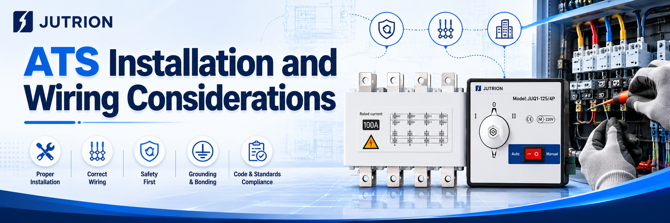
Key Installation Requirements
Installation environment:
Avoid humid, dusty, corrosive gas, and strong vibration areas. The ambient temperature should be controlled within -25°C to +40°C, the cabinet should have good ventilation and heat dissipation, and the protection rating should match the actual site conditions.
Installation fixing:
Install the ATS vertically in the upright position. The cabinet should remain level and stable, with sufficient space reserved for inspection and operation. Inclined or inverted installation is strictly prohibited. When multiple units are arranged together, adequate spacing for heat dissipation should be reserved.
Safety clearance:
Standard electrical clearance should be maintained between different phase conductors and between incoming and outgoing lines. The insulation withstand requirements must be met to prevent creepage and phase-to-phase discharge.
Grounding requirements:
The equipment enclosure and cabinet must be reliably grounded. The grounding conductor specification should comply with the applicable electrical code requirements to eliminate potential electric leakage hazards.
Core Wiring Requirements
Phase sequence verification:
Strictly distinguish the incoming phase sequence of the normal power source and the backup power source, and ensure that the phase positions of both power sources are consistent. Incorrect phase sequence may cause transfer failure or equipment damage.
Separation of incoming and outgoing lines:
The incoming terminals are connected to the main and backup power sources, while the outgoing terminals are uniformly connected to the downstream load. Reverse wiring or mixed wiring is not allowed. Wiring must follow the terminal layout and identification marks of the equipment.
Cable selection:
The conductor current-carrying capacity must be greater than the rated current of the switch, and should meet the requirements for voltage drop and temperature rise. Wiring terminals must be firmly tightened to prevent false contact and overheating caused by looseness.
Neutral conductor handling:
3P/4P switches must be wired according to the system configuration. The neutral conductors of the two power sources must never be mixed or incorrectly connected, so as to avoid neutral circulating current and voltage shift problems.
Control circuits:
Secondary control wiring should be arranged neatly, with strong-current and weak-current circuits routed separately to reduce electromagnetic interference. Interlocking, communication, and generator start/stop circuits must be wired according to the drawings.
Inspection and Commissioning After Wiring
- Before energizing, check whether there is any short circuit, incorrect wiring, or missed connection, and tighten all wiring points.
- Test the automatic transfer function and manual transfer function in sequence, and verify that the actions of fault power-off and utility power recovery transfer-back are normal.
- Verify the delay parameters, protection logic, and interlocking signals to ensure they are consistent with the design scheme.
- During trial operation, observe the temperature rise of the switch, abnormal noise, and indicator light status. The ATS can only be put into formal operation when no abnormality is found.
Prohibited Actions
It is strictly forbidden to dismantle the mechanical and electrical interlocking mechanism without authorization; it is prohibited to manually close the two power sources in parallel; overload connection to the load is not allowed; and it is strictly forbidden to open the cover for wiring or disassembly while energized.
Common ATS Selection Mistakes and Troubleshooting Resources
The most common selection mistakes include choosing the ATS only according to load current without leaving a margin, mistaking an ATS for a UPS, failing to verify the pole configuration, overlooking generator start signal requirements, ignoring generator voltage build-up delay, failing to consider high-temperature derating, and directly applying a conventional generator-based solution to solar PV or energy storage systems.
Key Takeaways:
If ATS is treated simply as “just another ordinary switch to buy,” it will almost certainly create hidden risks later, such as wiring confusion, incorrect transfer actions, and even improper upstream tripping. A selection logic that can truly stand up to real-world testing must always follow this principle: define the system boundaries first, and then define the product parameters. Only after the system structure and application scenario are clearly understood should the pole configuration, control strategy, and protection coordination be determined, so that the final product model can be selected accurately.
Different types of projects have fundamentally different technical demands for ATS:
Residential buildings and commercial complexes: the core requirement is absolute reliability of basic switching action together with a balanced budget.
Large industrial facilities and critical infrastructure: priority must be given to upstream and downstream protection coordination, as well as the ability to withstand extreme short-circuit fault conditions.
Renewable energy and microgrid systems: low-level control logic compatibility and inverter coordination have become new technical priorities.
Therefore, it is meaningless to discuss ATS selection without reference to the actual system architecture. That is the essence of engineering design: there is no “one-size-fits-all” model here, only a solution tailored specifically to your system.
There is no universal ATS solution for every project. If you need help evaluating your system architecture, pole configuration, or protection coordination, you are welcome to contact our engineering team for professional support.
Frequently Asked Questions About ATS:
Q: If a PC Class ATS is used, is an upstream circuit breaker such as an MCCB or ACB still required?
A:Yes, it is absolutely necessary. A PC Class ATS is like the “railway switch operator” in a power distribution system: it is only responsible for changing the track, that is, switching the power source, but it is not responsible for braking, that is, interrupting short-circuit faults.
When a severe short circuit occurs, it can only withstand the extremely high rated short-time withstand current (Icw) for a short period, while waiting for the upstream MCCB or ACB to trip and clear the fault.
Without a circuit breaker acting as its protection, a PC Class ATS is very dangerous under short-circuit conditions.
Q:How should the rated current be selected? Is it enough to simply add up the load power shown on the drawings?
A:Never select it right at full-load current. Real engineering conditions are far more complicated than theoretical calculations. If the temperature inside the distribution cabinet rises to 50°C or even 60°C in summer, the equipment must operate under derating conditions. In addition, inductive loads such as pumps and fans can produce high inrush current during startup. For this reason, we usually recommend leaving at least a 20% safety margin above the actual maximum operating current.
Q:Can two power sources with different voltage levels share the same ATS?
A:This is strongly not recommended unless a specially customized controller is used. The ATS controller usually needs to sample the voltage of both power sources at the same time for comparison and decision-making. If the two power sources are not at the same voltage level, the control logic may become completely disordered.
In standard engineering practice, the proper solution is to first unify the voltage reference through a transformer and then perform the transfer.
