

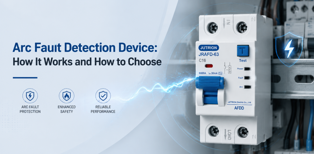
ອຸປະກອນກວດຈັບຄວາມຜິດພາດຈາກອາກໄຟຟ້າ JUTRION AFDD ສຳລັບການປ້ອງກັນອາກໄຟຟ້າ ແລະ ຄວາມປອດໄພທາງໄຟຟ້າ“16 A AFDD” ບໍ່ແມ່ນຂໍ້ກຳນົດທີ່ຄົບຖ້ວນ. ມັນບໍ່ໄດ້ບອກຜູ້ສະໜອງວ່າມາດຕະຖານຜະລິດຕະພັນປ້ອງກັນອາກໄຟຟ້າໃດທີ່ນຳໃຊ້, ຕ້ອງລວມການປ້ອງກັນໂຫຼດເກີນ ແລະ ກະແສຕົກຄ້າງຫຼືບໍ່, ຕ້ອງການຄວາມສາມາດໃນການຕັດວົງຈອນລັດເທົ່າໃດ, ຈັດການສາຍນິວທຣອນແນວໃດ, ຫຼື ອຸປະກອນນັ້ນໄດ້ຮັບການອະນຸມັດສຳລັບຕູ້ຈ່າຍໄຟທີ່ຕັ້ງໃຈໄວ້ຫຼືບໍ່. ການລະເວັ້ນເຫຼົ່ານັ້ນສາມາດປ່ຽນແນວຄວາມຄິດການປ້ອງກັນອັກຄີໄພທີ່ຖືກຕ້ອງໃຫ້ກາຍເປັນລາຍການວັດສະດຸທີ່ບໍ່ເຂົ້າກັນໄດ້.
ກົດການເລືອກທີ່ໃຊ້ໄດ້ຈິງແມ່ນເລີ່ມຈາກວົງຈອນສຸດທ້າຍອອກມາຂ້າງນອກ. ກ່ອນອື່ນໃຫ້ຢືນຢັນວ່າລະຫັດການຕິດຕັ້ງຮຽກຮ້ອງ ຫຼື ແນະນຳໃຫ້ມີການປ້ອງກັນອາກໄຟຟ້າສຳລັບວົງຈອນນັ້ນຫຼືບໍ່. ຈາກນັ້ນເລືອກສະຖາປັດຕະຍະກຳການປ້ອງກັນ, ປະສານງານທຸກຄ່າພິກັດທາງໄຟຟ້າ, ແລະ ຈັບຄູ່ອຸປະກອນໃຫ້ເຂົ້າກັບຕູ້ຈ່າຍໄຟ. ອຸປະກອນ ກວດຈັບຄວາມຜິດພາດຈາກອາກໄຟຟ້າ (AFDD) ເພີ່ມການປ້ອງກັນຕໍ່ກັບອາກໄຟຟ້າແບບອະນຸກົມ ແລະ ຂະໜານທີ່ເປັນອັນຕະລາຍ; ມັນບໍ່ໄດ້ທົດແທນ MCB, RCD, RCBO, SPD, ຫຼື ການປະຕິບັດການເດີນສາຍໄຟທີ່ຖືກຕ້ອງໂດຍອັດຕະໂນມັດ.
ຈຸດສຳຄັນ
- AFDD ກວດຈັບຮູບແບບອາກໄຟຟ້າແບບອະນຸກົມ ແລະ ຂະໜານທີ່ເປັນອັນຕະລາຍ ທີ່ອາດຈະບໍ່ສ້າງກະແສເກີນ ຫຼື ກະແສຮົ່ວລົງດິນພຽງພໍທີ່ຈະເຮັດໃຫ້ MCB ຫຼື RCD ແບບທຳມະດາເຮັດວຽກ.
- AFDD ເສີມອຸປະກອນປ້ອງກັນອື່ນໆ ແທນທີ່ຈະທົດແທນພວກມັນ. ການປ້ອງກັນໂຫຼດເກີນ, ວົງຈອນລັດ, ກະແສຕົກຄ້າງ, ແລະ ແຮງດັນເກີນຍັງຕ້ອງໄດ້ຈັດຫາໃຫ້ຢູ່ບ່ອນທີ່ຕ້ອງການ.
- ມາດຕະຖານຜະລິດຕະພັນ ແລະ ການຕິດຕັ້ງຕອບຄຳຖາມທີ່ແຕກຕ່າງກັນ. IEC 62606 ກວມເອົາຂໍ້ກຳນົດຜະລິດຕະພັນ AFDD, ໃນຂະນະທີ່ກົດລະບຽບການເດີນສາຍໄຟແຫ່ງຊາດກຳນົດວ່າຕ້ອງການ ຫຼື ແນະນຳໃຫ້ມີການປ້ອງກັນຢູ່ບ່ອນໃດ.
- ສະຖາປັດຕະຍະກຳການປ້ອງກັນມີຜົນກະທົບຕໍ່ການອອກແບບວົງຈອນທັງໝົດ. ເຄື່ອງ AFDD ແບບດ່ຽວ, AFDD-MCB, AFDD-RCBO ແລະ ຊຸດປະສົມໂມດູນທີ່ໄດ້ຮັບການອະນຸມັດ ມີຊຸດຟັງຊັນທີ່ແຕກຕ່າງກັນ.
- ກະແສໄຟຟ້າທີ່ກຳນົດໄວ້ຢ່າງດຽວບໍ່ພຽງພໍສຳລັບການເລືອກ. ແຮງດັນ, ຄວາມຖີ່, ຂົ້ວ, ເສັ້ນໂຄ້ງ, ຄວາມສາມາດໃນການຕັດວົງຈອນ, ປະເພດ RCD, ບັສບາ, ຂົ້ວຕໍ່, ຄວາມກວ້າງໂມດູນ ແລະ ເງື່ອນໄຂຂອງຕູ້ກໍ່ຕ້ອງກົງກັນນຳ.
- ການຕິດຕັ້ງ ແລະ ການທົດສອບທີ່ຖືກຕ້ອງແມ່ນຈຳເປັນຫຼາຍ. ການເດີນສາຍນິວຕຣອນ, ແຮງບິດຂອງຂົ້ວຕໍ່, ສະພາບຄວາມຮ້ອນ, ຂັ້ນຕອນການທົດສອບ ແລະ ການຊີ້ບອກສາເຫດການຕັດວົງຈອນ ລ້ວນສົ່ງຜົນຕໍ່ການເຮັດວຽກທີ່ໜ້າເຊື່ອຖື ແລະ ການຊອກຫາຂໍ້ບົກພ່ອງ.
ໃຊ້ເຈັດຈຸດຕໍ່ໄປນີ້ເພື່ອປຽບທຽບຕົວເລືອກ AFDD ສຳລັບວົງຈອນສະເພາະ ແລະ ຕະຫຼາດເປົ້າໝາຍ.
| ການຕັດສິນໃຈ | ຄຳຖາມທີ່ຕ້ອງຕອບ | ເປັນຫຍັງມັນຈຶ່ງປ່ຽນແປງການເລືອກ |
|---|---|---|
| ຂອບເຂດກົດລະບຽບ | ປະເທດໃດ, ສະບັບລະຫັດ, ປະເພດການຄອບຄອງ, ປະເພດວົງຈອນ ແລະ ກະແສໄຟຟ້າທີ່ກຳນົດໄວ້ແມ່ນໃຊ້ໄດ້ບໍ? | ຂໍ້ກຳນົດ AFDD ບໍ່ແມ່ນສາກົນ ແລະ ສາມາດປ່ຽນແປງໄດ້ຕາມການຮັບຮອງເອົາຂອງແຕ່ລະປະເທດ. |
| ລະບົບຜະລິດຕະພັນ | ໂຄງການແມ່ນ IEC AFDD, UK BS EN AFDD ຫຼື AFCI ອາເມລິກາເໜືອບໍ? | ມາດຕະຖານ, ການຈັດອັນດັບ, ການຮັບຮອງ, ອິນເຕີເຟດແຜງ ແລະ ຄຳສັບເຕັກນິກແຕກຕ່າງກັນ. |
| ສະຖາປັດຕະຍະກຳການປົກປ້ອງ | ການກວດຈັບອາກໄຟຟ້າແມ່ນແບບດ່ຽວ, ປະສົມກັບ MCB ຫຼື ປະສົມກັບ RCBO ບໍ? | ການເລືອກນີ້ກຳນົດວ່າອຸປະກອນປ້ອງກັນເພີ່ມເຕີມໃດແດ່ທີ່ຍັງຈຳເປັນຢູ່. |
| ການຈັດອັນດັບໄຟຟ້າ | ຕ້ອງການແຮງດັນ, ຄວາມຖີ່, ກະແສ, ເສັ້ນໂຄ້ງ, ປະເພດກະແສຕົກຄ້າງ ແລະ ຄວາມສາມາດໃນການຕັດວົງຈອນແບບໃດ? | ແຕ່ລະຄ່າກົງກັບສະພາບການເຮັດວຽກ ຫຼື ສະພາບຂໍ້ບົກພ່ອງທີ່ແຕກຕ່າງກັນ. |
| ອິນເຕີເຟດການປະກອບ | ບອດ, ບັສບາ, ຂົ້ວ, ການຈັດສາຍນິວຕຣອນ, ຄວາມກວ້າງໂມດູນ ແລະ ອຸປະກອນເສີມໃດແດ່ທີ່ໃຊ້ໄດ້? | ການໃສ່ໄດ້ທາງກົນຈັກຢ່າງດຽວບໍ່ໄດ້ສ້າງຄວາມເຂົ້າກັນໄດ້ທາງໄຟຟ້າ ຫຼື ການຮັບຮອງ. |
| ຜົນສະທ້ອນດ້ານການດຳເນີນງານ | ຈະເກີດຫຍັງຂຶ້ນຖ້າວົງຈອນຕັດ ແລະ ຈະລະບຸສາເຫດໄດ້ແນວໃດ? | ຄວາມຕໍ່ເນື່ອງ, ການເລືອກສະເພາະ, ການຊີ້ບອກ ແລະ ການເຂົ້າເຖິງການບຳລຸງຮັກສາສົ່ງຜົນຕໍ່ການອອກແບບ. |
| ການສະໜັບສະໜູນຜະລິດຕະພັນ | ແຜ່ນຂໍ້ມູນ, ຄຳແນະນຳ, ໃບຢັ້ງຢືນ, ຕົວຢ່າງ ແລະ ບໍລິການປັບແຕ່ງໃດແດ່ທີ່ຈະຊ່ວຍໂຄງການ? | ເອກະສານທີ່ຊັດເຈນເຮັດໃຫ້ການປຽບທຽບ, ການຕິດຕັ້ງ, ການອະນຸມັດ, ແລະ ການສັ່ງຊ້ຳງ່າຍຂຶ້ນ. |
ລຳດັບນີ້ຊ່ວຍໃຫ້ຜູ້ຊື້ປຽບທຽບຜະລິດຕະພັນທີ່ທຽບເທົ່າກັນ ແລະ ສື່ສານຄວາມຕ້ອງການຂອງພວກເຂົາຢ່າງມີປະສິດທິພາບ. ມັນຍັງແຍກການຕັດສິນໃຈທີ່ມັກສັບສົນກັນ. ຕົວຢ່າງ, ເສັ້ນໂຄ້ງຕັດວົງຈອນ C ອະທິບາຍໜ້າທີ່ກະແສເກີນ; ມັນບໍ່ໄດ້ອະທິບາຍຄວາມອ່ອນໄຫວຕໍ່ອາກ. ເຄື່ອງໝາຍ 30 mA ອະທິບາຍການປ້ອງກັນກະແສຮົ່ວ; ມັນບໍ່ໄດ້ພິສູດວ່າອຸປະກອນມີຟັງຊັນ AFDD.
ອາກໄຟຟ້າແມ່ນຫຍັງ, ແລະ ເປັນຫຍັງມັນຈຶ່ງເຮັດໃຫ້ເກີດໄຟໄໝ້ໄດ້?
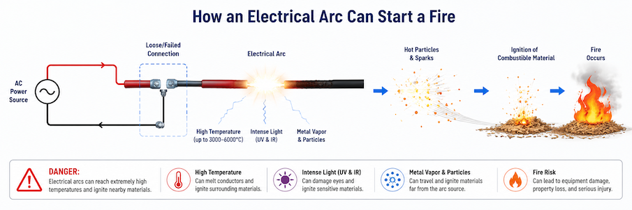
ອາກໄຟຟ້າແມ່ນການໄຫຼຂອງກະແສຢ່າງຕໍ່ເນື່ອງຜ່ານຊ່ອງວ່າງທີ່ຖືກໄອອອນໄນຊ໌ລະຫວ່າງຈຸດນຳໄຟຟ້າ. ໃນສະວິດທີ່ດີ, ອາກສັ້ນໆອາດເກີດຂຶ້ນເມື່ອໜ້າສຳພັດເປີດອອກ ແລະ ປົກກະຕິຈະຖືກຄວບຄຸມໄວ້ໂດຍອຸປະກອນ. ອາກຄວາມຜິດພາດແຕກຕ່າງກັນ: ມັນເກີດຂຶ້ນໂດຍບໍ່ຕັ້ງໃຈທີ່ສນວນທີ່ເສຍຫາຍ, ຕົວນຳທີ່ຫັກ, ຫຼື ການເຊື່ອມຕໍ່ທີ່ບໍ່ດີ ແລະ ສາມາດປ່ອຍຄວາມຮ້ອນຮຸນແຮງຊ້ຳໆໃສ່ວັດສະດຸໃກ້ຄຽງ.
ອຸປະກອນ AFDD ມີຄຸນຄ່າເພາະບາງອາກທີ່ອັນຕະລາຍຍັງຢູ່ຕ່ຳກວ່າລະດັບການເຮັດວຽກຂອງອຸປະກອນປ້ອງກັນແບບດັ້ງເດີມ. ອາກແບບອະນຸກົມສາມາດເກີດຂຶ້ນໄດ້ທີ່ຈຸດຕໍ່ສາຍຫຼວມ, ຕົວນຳທີ່ຫັກບາງສ່ວນ, ຫຼືໜ້າສຳຜັດປລັກທີ່ເສຍຫາຍ. ໂຫຼດຍັງຄົງຢູ່ໃນວົງຈອນອະນຸກົມກັບຈຸດຜິດພາດ, ດັ່ງນັ້ນໂຫຼດ 6 A ສາມາດດຶງກະແສປະມານປົກກະຕິຕໍ່ໄປໄດ້ ໃນຂະນະທີ່ຄວາມຮ້ອນຮຸນແຮງເກີດຂຶ້ນຢູ່ພື້ນທີ່ສຳຜັດນ້ອຍໆ. ເບຣກເກີ 16 A ເບຣກເກີຂະໜາດນ້ອຍ (MCB) ບໍ່ມີເຫດຜົນດ້ານໂຫຼດເກີນທີ່ຈະຕັດວົງຈອນ, ແລະ RCD ອາດຈະບໍ່ເຫັນຄວາມບໍ່ສົມດຸນ ຖ້າກະແສໄຟຟ້າໄຫຼກັບຜ່ານສາຍນິວທຣອນ.
ອາກແບບຂະໜານເກີດຂຶ້ນລະຫວ່າງຕົວນຳທີ່ມີສັກກະຍະພາບຕ່າງກັນ. ມັນສາມາດເກີດຕາມສາຍສນວນທີ່ເສຍຫາຍຈາກຕະປູຄວງ, ການກົດທັບ, ຄວາມຊຸ່ມ, ແສງອັນຕະລາຍ UV, ສັດຕູພືດ, ຫຼືການເສື່ອມສະພາບຈາກຄວາມຮ້ອນ. ເສັ້ນທາງຂອງອາກອາດຈຳກັດແລະຕັດກະແສໄຟຟ້າ, ເຮັດໃຫ້ເບຣກເກີແບບດັ້ງເດີມບໍ່ເຫັນການລັດວົງຈອນແບບໂລຫະທີ່ຄົງທີ່. ອາກລະຫວ່າງສາຍໄຟຟ້າກັບດິນອາດເຮັດໃຫ້ RCD ເຮັດວຽກ, ແຕ່ອາກລະຫວ່າງສາຍໄຟຟ້າກັບນິວທຣອນສາມາດຍັງຄົງສົມດຸນຈາກມຸມມອງຂອງ RCD.
ສະພາບເຕືອນໄພທົ່ວໄປປະກອບມີ ຈຸດຕໍ່ສາຍຂອງປລັກສຽບຫຼວມ, ໜ້າສຳຜັດປລັກສຽບສຶກຫຼໍ, ສາຍໄຟຖືກໜີບຢູ່ຫຼັງເຟີນິເຈີ, ຕົວນຳຖືກເສຍຫາຍຕອນປອກສາຍ, ສາຍໄຟອ່ອນຖືກງໍຊ້ຳໆໃກ້ເຄື່ອງໃຊ້ໄຟຟ້າ, ແລະສາຍສນວນຖືກສະກູຫຼືຕະປູເຈາະຜ່ານ. ບາງຈຸດຜິດພາດເລີ່ມຕົ້ນເປັນຈຸດຕໍ່ທີ່ມີຄວາມຕ້ານທານສູງ ທີ່ຮ້ອນຂຶ້ນແລະເກີດການອອກຊິໄດຊ໌ ກ່ອນທີ່ອາກແບບບໍ່ຕໍ່ເນື່ອງຈະປາກົດ. ບາງຈຸດເກີດຂຶ້ນຕາມເສັ້ນທາງສາຍສນວນທີ່ກາຍເປັນຄາບອນ ຫຼັງຈາກຄວາມເສຍຫາຍເດີມ. ກົນໄກເຫຼົ່ານີ້ອະທິບາຍວ່າເປັນຫຍັງການຂັນສະກູໃຫ້ຖືກແຮງບິດ, ການຈັດວາງສາຍໄຟຢ່າງລະມັດລະວັງ, ອຸປະກອນເສີມທີ່ເໝາະສົມ, ແລະການກວດກາເປັນໄລຍະ ຍັງຄົງສຳຄັນ ເຖິງແມ່ນວ່າຈະຕິດຕັ້ງອຸປະກອນປ້ອງກັນ AFDD ແລ້ວກໍຕາມ.
ອຸປະກອນປົກກະຕິກໍ່ສາມາດສ້າງລາຍເຊັນໄຟຟ້າທີ່ຄ້າຍຄືບາງສ່ວນຂອງຮູບຄື້ນອາກໄຟ. ໜ້າສຳຜັດສະວິດ, ຣີເລ, ດິມເມີ, ມໍເຕີແບບມີແປງຖ່ານ, ແລະ ແຫຼ່ງຈ່າຍໄຟແບບສະວິດຕິ້ງ ແມ່ນຕົວຢ່າງທີ່ຄຸ້ນເຄີຍ. AFDD ທີ່ໄດ້ມາດຕະຖານໃຊ້ຄຸນລັກສະນະສັນຍານຫຼາຍຢ່າງ ແລະ ໄລຍະເວລາຂອງມັນ ແທນທີ່ຈະຕອບສະໜອງຕໍ່ທຸກໆປະກາຍໄຟ ຫຼື ສິ່ງລົບກວນຄວາມຖີ່ສູງ. ການຈຳແນກນີ້ຮອງຮັບການເຮັດວຽກປົກກະຕິ ໃນຂະນະທີ່ອະນຸຍາດໃຫ້ອຸປະກອນຕອບສະໜອງເມື່ອຮູບແບບອັນຕະລາຍບັນລຸເງື່ອນໄຂການຕັດວົງຈອນຂອງມັນ.
AFDD ວິເຄາະຄຸນລັກສະນະທາງໄຟຟ້າຢ່າງຕໍ່ເນື່ອງ ເຊັ່ນ ໄລຍະເວລາຂອງກຸ່ມສັນຍານ, ຄວາມບໍ່ສະໝໍ່າສະເໝີ, ອົງປະກອບຄວາມຖີ່ສູງ, ຄວາມບໍ່ຕໍ່ເນື່ອງຂອງກະແສໄຟ, ແລະ ພຶດຕິກຳອ້ອມຈຸດຕັດສູນຂອງກະແສສະຫຼັບ. ອັນກໍລະທິມຂອງມັນຕ້ອງຈຳແນກຮູບແບບອັນຕະລາຍອອກຈາກອາກໄຟຈາກການສະວິດປົກກະຕິ, ການເຮັດວຽກຂອງຣີເລ, ດິມເມີ, ມໍເຕີແບບມີແປງຖ່ານ, ແລະ ແຫຼ່ງຈ່າຍໄຟອີເລັກໂທຣນິກ. ເມື່ອເງື່ອນໄຂທີ່ກຳນົດໄວ້ຖືກບັນລຸ, ມັນຈະສັ່ງໃຫ້ກົນໄກເປີດວົງຈອນຕັດການເຊື່ອມຕໍ່.
ຫຼັກການເຮັດວຽກນີ້ນຳໄປສູ່ຂອບເຂດການເລືອກສາມຢ່າງ:
- AFDD ບໍ່ແມ່ນພຽງແຕ່ MCB ທີ່ມີຄວາມອ່ອນໄຫວຫຼາຍກວ່າ. ຂະໜາດກະແສໄຟ ແລະ ການຮັບຮູ້ຮູບແບບອາກໄຟ ແມ່ນຫຼັກການປ້ອງກັນທີ່ແຕກຕ່າງກັນ.
- AFDD ບໍ່ແມ່ນ RCD. ຂີດຈຳກັດກະແສຮົ່ວລົງດິນ ເຊັ່ນ 30 mA ບໍ່ໄດ້ອະທິບາຍການກວດຈັບອາກໄຟ.
- AFDD ບໍ່ສາມາດຊົດເຊີຍສາຍໄຟທີ່ມີຂະໜາດຕໍ່າກວ່າກຳນົດ, ຄວາມສາມາດລັດວົງຈອນບໍ່ພຽງພໍ, ປະເພດ RCD ທີ່ຜິດ, ຫຼື ຈຸດຕໍ່ທີ່ບໍ່ດີ.
ໃນພາກປະຕິບັດ, ຂ້ອຍທຳອິດຈັດແຜນຟັງຊັນການປ້ອງກັນທີ່ຕ້ອງການໃນຕາຕະລາງແມທຣິກ: ໂຫຼດເກີນ, ລັດວົງຈອນ, ກະແສຕົກຄ້າງ, ອາກໄຟຟ້າ, ແລະ ແຮງດັນເກີນຊົ່ວຄາວ. ແຕ່ລະຟັງຊັນທີ່ຕ້ອງການຕ້ອງຖືກມອບໝາຍໃຫ້ອຸປະກອນທີ່ເໝາະສົມ ຫຼື ຜະລິດຕະພັນລວມ. ສິ່ງນີ້ເປີດເຜີຍການປ້ອງກັນທີ່ຂາດຫາຍໄປ ແລະ ຫຼີກລ່ຽງການຈ່າຍສອງເທື່ອສຳລັບຟັງຊັນດຽວກັນໂດຍບໍ່ເຂົ້າໃຈການປະສານງານ.
| ອຸປະກອນ/ຟັງຊັນ | ສະພາວະຫຼັກທີ່ກວດຈັບ | ສິ່ງທີ່ມັນບໍ່ໄດ້ທົດແທນໂດຍທົ່ວໄປ |
|---|---|---|
| MCB ຫຼື ຟິວ | ການໂຫຼດເກີນ ແລະ ກະແສເກີນວົງຈອນສັ້ນ | ການກວດຈັບກະແສຕົກຄ້າງ ຫຼື ຮູບແບບອາກ |
| RCCB/RCD | ຄວາມບໍ່ສົມດຸນຂອງກະແສຕົກຄ້າງ | ການປ້ອງກັນກະແສເກີນ ເວັ້ນເສຍແຕ່ວ່າຖືກລວມເຂົ້າໂດຍສະເພາະ |
| RCBO | ກະແສເກີນບວກກັບກະແສຕົກຄ້າງ | ການກວດຈັບອາກ ເວັ້ນເສຍແຕ່ວ່າຜະລິດຕະພັນນັ້ນເປັນ AFDD-RCBO ຢ່າງຊັດເຈນ |
| AFDD | ລາຍເຊັນອາກອັນຕະລາຍທີ່ຖືກກຳນົດໄວ້ | ໜ້າທີ່ອື່ນໆທີ່ບໍ່ໄດ້ລະບຸໄວ້ໃນໃບຢັ້ງຢືນຜະລິດຕະພັນ |
| SPD | ການຈຳກັດແຮງດັນເກີນຊົ່ວຄາວ | ການປ້ອງກັນກະແສເກີນ, ກະແສຕົກຄ້າງ, ຫຼື ຄວາມຜິດພ່ອງຈາກອາກ |
ຢືນຢັນບ່ອນທີ່ກົດເກນຖືກນຳໃຊ້ ກ່ອນທີ່ຈະເລືອກຄ່າພິກັດ
ຄວາມສອດຄ່ອງຂອງຜະລິດຕະພັນ ແລະ ຄວາມສອດຄ່ອງຂອງການຕິດຕັ້ງ ຕອບຄຳຖາມທີ່ແຕກຕ່າງກັນ. ມາດຕະຖານຜະລິດຕະພັນບອກຜູ້ຜະລິດວ່າ AFDD ຖືກສ້າງ ແລະ ທົດສອບແນວໃດ. ມາດຕະຖານການຕິດຕັ້ງບອກຜູ້ອອກແບບວ່າມາດຕະການປ້ອງກັນໃດຖືກຮຽກຮ້ອງ ຫຼື ແນະນຳ. ກົດໝາຍແຫ່ງຊາດ ແລະ ອົງການທີ່ມີອຳນາດຕັດສິນກຳນົດວ່າສະບັບໃດຖືກບັງຄັບໃຊ້.
ໂຄງການ IEC: ໃຊ້ມາດຕະຖານຜະລິດຕະພັນ ແລະ ການຕິດຕັ້ງຮ່ວມກັນ
IEC 62606:2013+A1:2017+A2:2022, ສະບັບລວມ 1.2, ນຳໃຊ້ກັບອຸປະກອນກວດຈັບ ແລະ ປ້ອງກັນຄວາມຜິດພ່ອງຈາກອາກ ສຳລັບການນຳໃຊ້ໃນຄົວເຮືອນ ແລະ ສະຖານທີ່ຄ້າຍຄືກັນໃນວົງຈອນ AC. ມັນຮັບຮູ້ອຸປະກອນທີ່ມີວິທີເປີດວົງຈອນທີ່ໃຊ້ກັບການປ້ອງກັນທີ່ຖືກປະກາດ, ຜະລິດຕະພັນທີ່ລວມເອົາອຸປະກອນປ້ອງກັນອື່ນ, ແລະ ໜ່ວຍກວດຈັບອາກແຍກຕ່າງຫາກທີ່ປະກອບກັບອຸປະກອນປ້ອງກັນທີ່ຖືກປະກາດ. ຂອບເຂດນີ້ກຳນົດຕະກຸນຜະລິດຕະພັນ; ມັນບໍ່ໄດ້ຕັດສິນດ້ວຍຕົວມັນເອງທຸກສະຖານທີ່ທີ່ AFDD ຕ້ອງຖືກຕິດຕັ້ງ.
ບໍລິບົດການຕິດຕັ້ງແມ່ນພົບເຫັນຢູ່ໃນມາດຕະຖານເຊັ່ນ IEC 60364-4-42:2024, ເຊິ່ງກ່າວເຖິງການປ້ອງກັນຜົນກະທົບຈາກຄວາມຮ້ອນ. ການປັບປຸງປີ 2024 ຂອງມັນໄດ້ຈັດລະບຽບໃໝ່ ແລະ ຂະຫຍາຍຂໍ້ກຳນົດສຳລັບສະຖານທີ່ທີ່ຜົນສະທ້ອນຈາກໄຟໄໝ້ຮ້າຍແຮງ. ມາດຕະຖານແຫ່ງຊາດທີ່ອີງໃສ່ IEC 60364 ອາດຈະນຳໃຊ້ຂໍ້ກຳນົດເຫຼົ່ານີ້ໃນເວລາທີ່ແຕກຕ່າງກັນ ຫຼື ມີການດັດແປງ. ດັ່ງນັ້ນ, “ປະເທດ IEC” ບໍ່ແມ່ນຄຳຖະແຫຼງການປະຕິບັດຕາມທີ່ພຽງພໍ.
ບັນທຶກປະເທດປາຍທາງ, ມາດຕະຖານແຫ່ງຊາດທີ່ແນ່ນອນ ແລະ ສະບັບ, ການຈັດປະເພດການຄອບຄອງ, ວ່າວົງຈອນຈ່າຍໄຟໃຫ້ປລັກສຽບ ຫຼື ອຸປະກອນຕິດຕັ້ງຄົງທີ່, ພິກັດຂອງມັນ, ແລະ ຂໍ້ຍົກເວັ້ນຕ່າງໆ. ຖ້າຜະລິດຕະພັນມີຈຸດປະສົງສຳລັບຫຼາຍຕະຫຼາດ, ໃຫ້ສ້າງຕາຕະລາງຕະຫຼາດແທນທີ່ຈະເປັນການອ້າງສິດທົ່ວໂລກອັນດຽວ.
ສະຫະລາຊະອານາຈັກ: ຄວບຄຸມການປ່ຽນຜ່ານສະບັບ
ຂໍ້ກຳນົດຂອງອັງກິດຕ້ອງລະບຸສະຖານະປັດຈຸບັນຂອງ BS 7671. ເຄື່ອງມື ກວດສອບສະບັບ IET ລະບຸວ່າ BS 7671:2018+A4:2026 ໄດ້ຖືກເຜີຍແຜ່ແລ້ວ ແລະ ວ່າ Amendment 3:2024 ຍັງຄົງມີຜົນບັງຄັບໃຊ້ຈົນເຖິງວັນທີ 15 ຕຸລາ 2026. ໂຄງການທີ່ອອກແບບໃນຊ່ວງການປ່ຽນຜ່ານນີ້ຄວນລະບຸວ່າສະບັບໃດເປັນພື້ນຖານສັນຍາ ແທນທີ່ຈະປະສົມຂໍ້ຄວາມຈາກບົດຄວາມເວັບ A2, A3, ແລະ A4.
ຢ່າຄັດລອກລາຍຊື່ “ອາຄານບັງຄັບ” ຈາກບລັອກຜູ້ຕິດຕັ້ງທີ່ບໍ່ມີວັນທີ. ກວດສອບກົດລະບຽບປັດຈຸບັນ, ຄຳນິຍາມ, ຂອບເຂດວົງຈອນ, ຂໍ້ຍົກເວັ້ນ, ແລະ ຂໍ້ກຳນົດຂອງໂຄງການ. ມາດຕະຖານຂອງລູກຄ້າ, ຜູ້ຮັບປະກັນໄພ, ຍຸດທະສາດດັບເພີງ, ຫຼື ການປະເມີນຄວາມສ່ຽງທີ່ມີເອກະສານ ອາດຈະໃຫ້ເຫດຜົນໃນການປ້ອງກັນເກີນກວ່າກົດລະບຽບແຫ່ງຊາດຂັ້ນຕ່ຳ.
ອາເມລິກາເໜືອ: ລະບຸ AFCI, ບໍ່ແມ່ນ AFDD ທົ່ວໄປຂອງ IEC
ໃນສະຫະລັດອາເມລິກາ ແລະ ການາດາ, ຄຳສັບທີ່ໃຊ້ທົ່ວໄປແມ່ນ ເຄື່ອງຕັດວົງຈອນປ້ອງກັນອາກໄຟຟ້າລັດວົງຈອນ (AFCI). UL Solutions ລະບຸ UL 1699 ສຳລັບການປະເມີນ AFCI ຂອງສະຫະລັດ ແລະ CSA C22.2 No. 270 ສຳລັບການາດາ. ຜະລິດຕະພັນອາເມລິກາເໜືອປະກອບມີຮູບແບບເບຣກເກີວົງຈອນ ແລະ ເຕົ້າຮັບ ພ້ອມດ້ວຍໝວດການນຳໃຊ້ທີ່ກຳນົດໄວ້.
ເຄື່ອງຕັດວົງຈອນປ້ອງກັນອາກຄ໌ຜິດປົກກະຕິ (AFDD) ແບບຮາງ DIN ຕາມມາດຕະຖານ IEC 62606 ແລະ AFCI ທີ່ໄດ້ຮັບການຮັບຮອງ UL ບໍ່ສາມາດໃຊ້ແທນກັນໄດ້ພຽງເພາະທັງສອງຕອບສະໜອງຕໍ່ອາກຄ໌. ແຮງດັນ, ຄວາມຖີ່, ພິກັດຂອງວົງຈອນ, ການຮັບຮອງຕູ້ແຜງໄຟຟ້າ, ການເຊື່ອມຕໍ່ສາຍນິວຕຣອນ, ໂປຣແກຣມທົດສອບ ແລະ ລະຫັດການຕິດຕັ້ງແຕກຕ່າງກັນ. ສຳລັບວຽກງານໃນສະຫະລັດອາເມລິກາ, ຍັງຕ້ອງກວດສອບສະບັບ NEC ທີ່ໄດ້ຮັບການຮັບຮອງໃນທ້ອງຖິ່ນ ແລະ ການແກ້ໄຂເພີ່ມເຕີມ. ສຳລັບເບຣກເກີທົດແທນ, ການ ເຄື່ອງໝາຍ UL ແລະ ຄຳແນະນຳການນຳໃຊ້ ເນັ້ນໃສ່ການລະບຸຜະລິດຕະພັນ, ຄຳແນະນຳ ແລະ ຄວາມເຂົ້າກັນໄດ້ກັບຕູ້ແຜງໄຟຟ້າທີ່ກ່ຽວຂ້ອງ.
ເລືອກສະຖາປັດຕະຍະກຳການປ້ອງກັນກ່ອນທີ່ຈະປຽບທຽບລຸ້ນ AFDD
IEC 62606 ອະນຸຍາດໃຫ້ມີຫຼາຍວິທີການກໍ່ສ້າງ, ແຕ່ລາຍການສິນຄ້າອາດຈະອະທິບາຍພວກມັນແຕກຕ່າງກັນ. ຄຳຖາມທາງວິສະວະກຳແມ່ນວ່າໜ້າທີ່ໃດແດ່ຢູ່ພາຍໃນຜະລິດຕະພັນທີ່ເລືອກ ແລະ ໜ້າທີ່ໃດຕ້ອງໄດ້ຮັບການສະໜອງໂດຍອຸປະກອນທີ່ກ່ຽວຂ້ອງທີ່ຖືກປະກາດ.
| ສະຖາປັດຕະຍະກຳ | ໜ້າທີ່ທີ່ມັກມີ | ການພິຈາລະນາຄວາມເໝາະສົມທີ່ສຸດ | ຄວາມສ່ຽງຫຼັກໃນການກວດສອບ |
|---|---|---|---|
| AFDD ພ້ອມອຸປະກອນເປີດວົງຈອນ | ການກວດຈັບອາກໄຟຟ້າ ແລະ ການເປີດວົງຈອນ | ໂຄງການທີ່ໃຊ້ອຸປະກອນປ້ອງກັນກະແສເກີນ ຫຼື ກະແສຮົ່ວໄຫຼທີ່ປະກາດແຍກຕ່າງຫາກ | ການສົມມຸດວ່າມີການປ້ອງກັນ MCB ຫຼື RCD ໃນຂະນະທີ່ບໍ່ມີ |
| AFDD ປະສົມປະສານກັບ MCB | ການປ້ອງກັນອາກໄຟຟ້າ, ກະແສເກີນ, ແລະ ວົງຈອນສັ້ນ | ວົງຈອນທີ່ການປ້ອງກັນກະແສຮົ່ວໄຫຼແຍກຕ່າງຫາກ ຫຼື ບໍ່ຈຳເປັນຕ້ອງມີ | ການລະເວັ້ນການປ້ອງກັນ RCD ທີ່ຈຳເປັນ ຫຼື ການໃຊ້ RCD ຮ່ວມທີ່ບໍ່ເໝາະສົມ |
| AFDD ປະສົມປະສານກັບ RCBO | ການປ້ອງກັນອາກໄຟຟ້າ, ກະແສເກີນ, ວົງຈອນສັ້ນ, ແລະ ກະແສຮົ່ວໄຫຼ | ການປ້ອງກັນວົງຈອນສຸດທ້າຍແຕ່ລະວົງ ແລະ ການແຍກຄວາມຜິດປົກກະຕິທີ່ຊັດເຈນກວ່າ | ການຖືວ່າລາຍລະອຽດ RCBO ທັງໝົດເປັນມາດຕະຖານ ໃນຂະນະທີ່ປະເພດ, ຄວາມອ່ອນໄຫວ, ເສັ້ນໂຄ້ງ, ແລະ ຈຳນວນຂົ້ວແຕກຕ່າງກັນ |
| ໜ່ວຍ AFD ບວກກັບອຸປະກອນປ້ອງກັນທີ່ປະກາດ | ຂຶ້ນກັບຊຸດປະສົມທີ່ໄດ້ຮັບການອະນຸມັດ | ລະບົບຜູ້ຜະລິດທີ່ອອກແບບສຳລັບການປະກອບໜ້າງານ | ການປະສົມໂມດູນທີ່ເຂົ້າກັນໄດ້ທາງສາຍຕາ ທີ່ບໍ່ເຄີຍຖືກປະເມີນຮ່ວມກັນ |
AFDD-RCBO ມັກຈະເປັນສະຖາປັດຕະຍະກຳທີ່ຊັດເຈນທີ່ສຸດສຳລັບວົງຈອນສຸດທ້າຍທີ່ຕ້ອງການທັງການປ້ອງກັນກະແສຮົ່ວໄຫຼເພີ່ມເຕີມ ແລະ ການຫຼຸດຜ່ອນຄວາມຜິດອາກໄຟຟ້າ. ມັນເພີ່ມການກວດຈັບອາກໄຟຟ້າໃສ່ໜ້າທີ່ກະແສເກີນ, ວົງຈອນສັ້ນ, ແລະ ກະແສຮົ່ວໄຫຼທີ່ກ່ຽວຂ້ອງກັບ RCBO. ການຈັດວາງນີ້ຈຳກັດການຕັດວົງຈອນຈາກກະແສຮົ່ວໄຫຼ ຫຼື ອາກໄຟຟ້າໃຫ້ຢູ່ວົງຈອນດຽວ ແລະ ຫຼຸດການເຊື່ອມຕໍ່ລະຫວ່າງກັນ. ປະເພດກະແສຮົ່ວໄຫຼຍັງຕ້ອງເໝາະສົມກັບໂຫຼດ, ເສັ້ນໂຄ້ງ MCB ຕ້ອງປະສານງານກັບສະພາບຄວາມຜິດ ແລະ ກະແສກະທັນຫັນ, ແລະ ອຸປະກອນຕ້ອງເຂົ້າກັນໄດ້ກັບຕູ້ຈ່າຍໄຟ.
ອຸປະກອນຕົ້ນທາງທີ່ໃຊ້ຮ່ວມກັນ RCCB ດ້ວຍວົງຈອນສຸດທ້າຍ AFDD-MCB ຫຼາຍໆອັນ ອາດຫຼຸດຕົ້ນທຶນອຸປະກອນ, ແຕ່ເຫດການກະແສຕົກຄ້າງເທື່ອດຽວສາມາດຕັດວົງຈອນຫຼາຍອັນ. ການຮົ່ວໄຫຼຈາກໂຫຼດອີເລັກໂທຣນິກຫຼາຍອັນສາມາດສະສົມໄດ້, ແລະການວິນິດໄສກໍຊັບຊ້ອນຂຶ້ນ. ຜູ້ອອກແບບຕ້ອງພິຈາລະນາການສູນເສຍການບໍລິການທີ່ບໍ່ຕ້ອງການ, ການເລືອກຕັດຕອບ, ການຮົ່ວໄຫຼລົງດິນທີ່ອະນຸຍາດໄດ້, ແລະກົດລະບຽບໃດໆທີ່ຮຽກຮ້ອງການປ້ອງກັນແຕ່ລະວົງຈອນ.
ໂມດູນແຍກຕ່າງຫາກໃຫ້ຄວາມຍືດຫຍຸ່ນເມື່ອຜູ້ຜະລິດປະກາດການປະສົມປະສານນັ້ນ. ຄວາມກວ້າງຄ້າຍຄືກັນ, ສີທີ່ກົງກັນ, ຫຼືລາງ DIN ຮ່ວມກັນ ບໍ່ໄດ້ຢືນຢັນດ້ວຍຕົວມັນເອງເຖິງການປະສານງານການລັດວົງຈອນ, ການເຊື່ອມໂຍງການຕັດຕອບ, ຫຼືປະສິດທິພາບອຸນຫະພູມຂອງຂົ້ວຕໍ່. ການແບ່ງປັນບອດທີ່ມີຢູ່ແລະລາຍລະອຽດການປ້ອງກັນກັບຜູ້ຜະລິດ ຊ່ວຍໃຫ້ງ່າຍຕໍ່ການລະບຸການປະສົມປະສານທີ່ເໝາະສົມ.
ບ່ອນທີ່ການປ້ອງກັນ AFDD ໃຫ້ຄຸນຄ່າຫຼາຍທີ່ສຸດ
AFDD ຖືກນຳໃຊ້ຕົ້ນຕໍໃນວົງຈອນສຸດທ້າຍ ທີ່ສາຍໄຟເສຍຫາຍ ຫຼືການເຊື່ອມຕໍ່ໄຟຟ້າທີ່ວ່າງ ອາດສ້າງອາກຟອດອັນຕະລາຍ ທີ່ການປ້ອງກັນກະແສເກີນ ຫຼືກະແສຕົກຄ້າງແບບທຳມະດາບໍ່ສາມາດກວດພົບໄດ້. ຄວາມຈຳເປັນຂອງການປ້ອງກັນ AFDD ຂຶ້ນກັບທັງຄວາມເປັນໄປໄດ້ຂອງຄວາມເສຍຫາຍຂອງສາຍໄຟ ແລະຜົນສະທ້ອນທີ່ອາດເກີດຂຶ້ນຈາກໄຟໄໝ້.
ຫ້ອງນອນ ແລະອາຄານທີ່ມີບ່ອນນອນພັກ
- ຫ້ອງນອນ, ໂຮງແຮມ, ສູນດູແລຜູ້ສູງອາຍຸ, ຫໍພັກນັກສຶກສາ, ບ່ອນພັກເຊົາ, ແລະສະພາບແວດລ້ອມການນອນທີ່ຄ້າຍຄືກັນ ແມ່ນໜຶ່ງໃນການນຳໃຊ້ທົ່ວໄປທີ່ສຸດສຳລັບ AFDD. ເນື່ອງຈາກຜູ້ພັກອາໄສອາດບໍ່ສັງເກດເຫັນກິ່ນ, ສຽງ, ຫຼືສັນຍານເບື້ອງຕົ້ນຂອງບັນຫາໄຟຟ້າໃນຂະນະນອນຫຼັບ, AFDD ຈຶ່ງໃຫ້ຊັ້ນການປ້ອງກັນເພີ່ມເຕີມ ໂດຍການກວດພົບອາກຟອດທີ່ເກີດຈາກການເຊື່ອມຕໍ່ທີ່ວ່າງ, ສາຍໄຟເສຍຫາຍ, ຫຼືສາຍເຄື່ອງໃຊ້ໄຟຟ້າທີ່ເສື່ອມສະພາບ.
ວົງຈອນທີ່ແນ່ນອນທີ່ຕ້ອງການການປ້ອງກັນ AFDD ແມ່ນຂຶ້ນກັບລະບຽບໄຟຟ້າທ້ອງຖິ່ນ ແລະ ມາດຕະຖານການຕິດຕັ້ງ. ຜູ້ອອກແບບຄວນພິຈາລະນາຄວາມຕໍ່ເນື່ອງຂອງໄຟຟ້າສຳລັບລະບົບສຸກເສີນ, ສັນຍານເຕືອນໄພ ແລະ ອຸປະກອນທີ່ກ່ຽວຂ້ອງກັບຄວາມປອດໄພອື່ນໆ.
ອາຄານໄມ້ ແລະ ສະພາບແວດລ້ອມທີ່ຕິດໄຟໄດ້ງ່າຍ
- ອາຄານໂຄງສ້າງໄມ້, ໂຮງງານຊ່າງໄມ້, ຍຸ້ງສາງ, ສະຖານທີ່ເກັບມ້ຽນ, ແລະ ສະຖານທີ່ອື່ນໆທີ່ມີວັດສະດຸຕິດໄຟໄດ້ງ່າຍ ມີຄວາມສ່ຽງຕໍ່ການເກີດໄຟໄໝ້ສູງກວ່າ ຖ້າເກີດອາກໄຟຟ້າ. AFDDs ສາມາດຊ່ວຍຫຼຸດຄວາມສ່ຽງນີ້ໄດ້ ໂດຍການຕັດວົງຈອນຄວາມຜິດພາດຈາກອາກໄຟຟ້າທີ່ກຳລັງພັດທະນາ ກ່ອນທີ່ມັນຈະກາຍເປັນແຫຼ່ງຈຸດໄຟ.
ການປ້ອງກັນດ້ວຍ AFDD ຄວນເປັນສ່ວນເສີມ—ບໍ່ແມ່ນມາແທນ—ການຕິດຕັ້ງສາຍໄຟທີ່ຖືກຕ້ອງ, ການປ້ອງກັນກະແສເກີນ, ການອອກແບບຕູ້ໄຟຟ້າ, ການກວດກາເປັນປະຈຳ, ແລະ ການຮັກສາຄວາມສະອາດທີ່ດີ.
ຫໍພິພິທະພັນ, ຫໍສະໝຸດ, ແລະ ອາຄານປະຫວັດສາດ
- ຫໍພິພິທະພັນ, ຫໍສະໝຸດ, ຫໍສະແດງສິລະປະ, ຫໍຈົດໝາຍເຫດ, ແລະ ອາຄານປະຫວັດສາດ ມັກຈະບັນຈຸຊັບສິນທາງວັດທະນະທຳ ຫຼື ປະຫວັດສາດທີ່ບໍ່ສາມາດທົດແທນໄດ້. ເນື່ອງຈາກສາຍໄຟຟ້າອາດຖືກເຊື່ອງໄວ້ຫຼັງຝາ ຫຼື ກວດກາໄດ້ຍາກ, AFDDs ສາມາດສະໜັບສະໜູນຍຸດທະສາດການປ້ອງກັນໄຟໄໝ້ໂດຍລວມ ໂດຍການຫຼຸດຄວາມເປັນໄປໄດ້ຂອງການຈຸດໄຟຈາກອາກໄຟຟ້າ.
ການປັບປຸງໃໝ່ ແລະ ການຕິດຕັ້ງໄຟຟ້າທີ່ເກົ່າແກ່
- ໂຄງການປັບປຸງໃໝ່ ແລະ ການຕິດຕັ້ງໄຟຟ້າທີ່ເກົ່າແກ່ ອາດມີສານຫຸ້ມສາຍທີ່ເສື່ອມສະພາບ, ກ່ອງຕໍ່ສາຍທີ່ເຂົ້າເຖິງບໍ່ໄດ້, ສາຍໄຟທີ່ເສຍຫາຍ, ຫຼື ສາຍໄຟທີ່ຖືກດັດແປງຫຼາຍຄັ້ງຕະຫຼອດອາຍຸການໃຊ້ງານ. ຄວາມເສຍຫາຍຂອງສາຍໄຟທີ່ເກີດຈາກການເຈາະ, ການກົດທັບ, ການສັ່ນສະເທືອນ, ຫຼື ການເຄື່ອນຍ້າຍຊ້ຳໆ ກໍ່ສາມາດເພີ່ມຄວາມເປັນໄປໄດ້ຂອງການເກີດອາກໄຟຟ້າໄດ້ເຊັ່ນກັນ.
ເມື່ອການກວດກາພົບວ່າມີຄວາມສ່ຽງຕໍ່ການເກີດໄຟໄໝ້ສູງ, ການປ້ອງກັນດ້ວຍ AFDD ອາດຖືກພິຈາລະນາສຳລັບວົງຈອນສຸດທ້າຍທີ່ໄດ້ຮັບຜົນກະທົບ ຕາມຂໍ້ກຳນົດການຕິດຕັ້ງທ້ອງຖິ່ນ.
ວົງຈອນກາງແຈ້ງ ແລະ ວົງຈອນທີ່ຖືກເສຍຫາຍເລື້ອຍໆ
- ສາຍໄຟກາງແຈ້ງ, ອຸປະກອນເຄື່ອນຍ້າຍໄດ້, ສາຍຕໍ່ພ່ວງ, ວົງຈອນປລັກສຽບໃນພື້ນທີ່ທີ່ຖືກຈັດຮູບແບບໃໝ່ເລື້ອຍໆ, ແລະ ການຕິດຕັ້ງທີ່ຖືກສັ່ນສະເທືອນ, ຄວາມຊຸ່ມ, ໜູ, ຫຼື ຄວາມເສຍຫາຍທາງກົນຈັກ ອາດມີຄວາມເປັນໄປໄດ້ສູງກວ່າຂອງການເສື່ອມສະພາບຂອງສາຍໄຟ. ເມື່ອເໝາະສົມ, AFDDs ສາມາດໃຫ້ການປ້ອງກັນເພີ່ມເຕີມສຳລັບວົງຈອນສຸດທ້າຍເຫຼົ່ານີ້ໄດ້ ໂດຍມີເງື່ອນໄຂວ່າອຸປະກອນທີ່ເລືອກນັ້ນຕອງຮັບແຮງດັນ, ກະແສ, ຄຸນລັກສະນະການໂຫຼດ, ແລະ ສະພາບແວດລ້ອມຂອງວົງຈອນ.
ຕົວຢ່າງການນຳໃຊ້
- ຫໍພັກນັກສຶກສາແຫ່ງໜຶ່ງຕິດຕັ້ງ AFDD-RCBO ໃນວົງຈອນປລັກສຽບຫ້ອງນອນ ທີ່ຈ່າຍໄຟໃຫ້ເຄື່ອງສາກ, ຄອມພິວເຕີ, ເຄື່ອງເຮັດຄວາມຮ້ອນແບບພົກພາ, ແລະ ເຄື່ອງໃຊ້ໄຟຟ້າໃນຊີວິດປະຈຳວັນອື່ນໆ. ໂດຍການໃຫ້ການປ້ອງກັນອາກໄຟຟ້າ, ກະແສເກີນ, ວົງຈອນສັ້ນ, ແລະ ກະແສຮົ່ວໄຫຼ ສຳລັບແຕ່ລະວົງຈອນສຸດທ້າຍ, ຄວາມຜິດພາດສາມາດຖືກແຍກອອກໄດ້ຢ່າງວ່ອງໄວ ໂດຍບໍ່ຕັດໄຟພື້ນທີ່ອື່ນທີ່ບໍ່ກ່ຽວຂ້ອງຂອງອາຄານ.
ການນຳໃຊ້ທີ່ຕ້ອງການວິທີແກ້ໄຂອາກໄຟຟ້າແບບອື່ນ
AFDDs ທີ່ອອກແບບມາສຳລັບການຕິດຕັ້ງໄຟຟ້າກະແສສະຫຼັບໃນຄົວເຮືອນ ແລະ ສະຖານທີ່ຄ້າຍຄືກັນ ບໍ່ຄວນຖືກນຳໃຊ້ໂດຍອັດຕະໂນມັດກັບສາຍປ້ອນອຸດສາຫະກຳສາມເຟດ, ຜົນຜະລິດຂອງໄດຣຟ໌ຄວາມໄວປ່ຽນແປງໄດ້, ວົງຈອນສາຍພານໂຊລາເຊລ (PV), ລະບົບເກັບພະລັງງານແບັດເຕີຣີ, ຫຼື ເຄືອຂ່າຍກະແສຕົງ (DC) ອື່ນໆ. ການນຳໃຊ້ເຫຼົ່ານີ້ມີຄຸນລັກສະນະທາງໄຟຟ້າ, ພຶດຕິກຳຂອງອາກໄຟຟ້າ, ແລະ ມາດຕະຖານຜະລິດຕະພັນທີ່ແຕກຕ່າງກັນ, ດັ່ງນັ້ນຈຶ່ງຕ້ອງການອຸປະກອນປ້ອງກັນສະເພາະ ທີ່ຖືກອອກແບບມາສຳລັບລະບົບເຫຼົ່ານັ້ນໂດຍສະເພາະ.
ມັນຍັງສຳຄັນທີ່ຈະຈຳແນກ AFDD ຈາກ ການປ້ອງກັນອາກໄຟຟ້າແຟລດ. AFDDs are intended to detect and interrupt dangerous electrical arc faults in final circuits to reduce fire risk, whereas arc-flash protection focuses on protecting personnel from high-energy arc-flash events in industrial switchgear through equipment design, energy-reduction methods, safe working procedures, and appropriate personal protective equipment (PPE). These two technologies address different hazards and should not be considered interchangeable.
Freeze the Electrical and Assembly Parameters
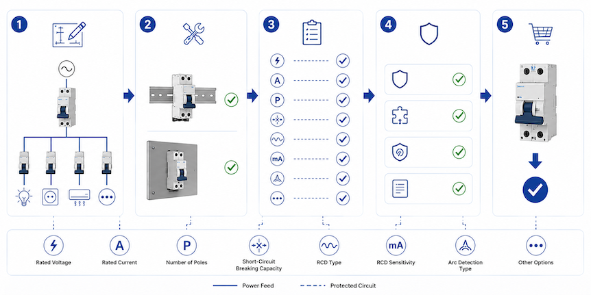
Once the architecture is decided, the AFDD schedule should be completed like any other engineered protective-device schedule. Each parameter represents a condition that the device must carry, detect, or interrupt.
Circuit Ratings: Voltage, Frequency, Current, and Poles
Confirm the nominal voltage, permitted voltage range, and supply frequency. The electronic detection circuit needs a valid supply; a 230 V, 50 Hz marking cannot be assumed suitable for 120 V, 60 Hz. If the product is marked for a range, confirm that all integrated protective functions operate throughout that range.
Identify single-phase, line-to-neutral, line-to-line, or other circuit arrangements. Check whether the device is 1P+N, two-pole, or another configuration, and which poles are protected and switched. Some products require designated line and neutral terminals or a specific supply/load orientation.
Rated current and conductor protection. The rated current is the continuous current the protective device can carry under defined conditions. It must satisfy the familiar coordination relationship between design current, protective-device rating, and conductor current-carrying capacity, with correction factors applied for ambient temperature, grouping, installation method, and thermal insulation.
Suppose a final circuit has a 13 A design current and its corrected conductor capacity is 18 A. A 16 A integrated AFDD-RCBO may be a candidate because the design current does not exceed the device rating and the device rating does not exceed the corrected conductor capacity. That simple check does not finish the design: voltage drop, disconnection time, inrush, terminal capacity, and board derating still matter.
Do not increase an AFDD from 16 A to 25 A merely to stop trips. If the trip indication shows overload, the load or circuit needs correction. If it shows an arc event, the higher current marking will not solve the arc signature and may leave the conductor underprotected.
Overcurrent Curve and Short-Circuit Capacity
For an integrated MCB or RCBO, the B, C, or other curve defines the instantaneous overcurrent operating range. C curve can tolerate more inrush than B curve, but it also needs higher fault current for instantaneous operation. The designer must verify the required automatic disconnection time using the applicable fault-loop or short-circuit calculation.
The curve does not adjust AFDD sensitivity. Changing curve to address an arc trip is a category error. Use trip indication and circuit testing to determine which function operated.
Breaking capacity and backup protection. The device’s rated short-circuit capacity must be adequate for the prospective short-circuit current at its installation point. A 6 kA device should not be selected for a calculated 8 kA location unless a manufacturer-documented backup arrangement increases the conditional capability under the exact conditions.
Where backup protection is used, record the upstream fuse or breaker model, rating, maximum prospective current, and applicable coordination table. A generic statement such as “protected by upstream MCCB” is not enough. The AFDD electronics do not compensate for contacts or terminals exposed beyond their short-circuit rating.
Residual-Current Sensitivity and Type
For an AFDD-RCBO, specify both rated residual operating current and RCD type. A 30 mA value is commonly associated with additional protection, but the applicable rule and circuit must be checked. It is a sensitivity value, not a universal fire-protection setting.
RCD type defines the residual-current waveforms the device can detect correctly. Type A is widely used where equipment can produce pulsating DC residual current. Loads involving frequency control, smooth DC components, or specialized power electronics may require another type according to the equipment instructions and national rules. Never assume that arc detection makes the residual-current type irrelevant.
Board, Busbar, Terminal, and Thermal Compatibility
Distribution-board compatibility deserves more than a photograph. Share the board series, rail, busbar geometry, phase position, terminal form, enclosure depth, module width, accessories, and maximum assembly current. A supplier can then recommend a suitable format and explain whether a new busbar, enclosure, or wiring arrangement is needed.
Check conductor material, cross-sectional range, stripping length, tightening torque, number of conductors allowed per terminal, and ferrule requirements. Confirm ambient-temperature and grouping derating. A row of heavily loaded electronic protective devices can run warmer than an isolated catalogue test condition.
For retrofit work, space must include conductor bending and safe access to test buttons and indicators. Replacing a one-module RCBO with a wider AFDD-RCBO can require a new enclosure. Moving circuits to make space can alter phase balance, RCD grouping, neutral routing, and schedules; it is not only a mechanical exercise.
Application Example: Choosing an AFDD for a Hotel Guest Room Circuit
The following hypothetical example shows how the decisions connect. It is not a universal design or a substitute for project calculations. Assume a 230 V, 50 Hz single-phase hotel-room socket circuit. The circuit supplies a maximum assessed load of 3.0 kW, uses copper conductors, requires 30 mA additional residual-current protection under the project rules, and originates in a compatible distribution board. The calculated prospective short-circuit current at the board is 3.4 kA. The applicable project risk assessment requires arc-fault protection because occupants sleep in the premises.
Step 1: Calculate the design current.
For this simplified single-phase resistive-equivalent assessment:
Ib = P / (V × PF)
ໂດຍທີ່ Ib is design current in amperes, P is active power in watts, V is circuit voltage in volts, and PF is power factor. Using 3,000 W, 230 V, and an assumed aggregate power factor of 0.95:
Ib = 3,000 / (230 × 0.95) = 13.7 A
A 16 A overcurrent function is a plausible starting point because its rated current exceeds the calculated 13.7 A design current. The result does not independently prove that 16 A is correct. The designer still needs the actual load profile, diversity rules, socket-circuit requirements, inrush behavior, and conductor calculation.
Step 2: Check the conductor relationship.
Assume the selected cable has a tabulated current-carrying capacity of 24 A under its reference installation method. The combined correction factor for ambient temperature, grouping, and thermal conditions is assumed to be 0.78. The corrected conductor capacity is:
Iz = It × C = 24 × 0.78 = 18.72 A
ໂດຍທີ່ Iz is corrected current-carrying capacity, It is tabulated capacity, and C is the combined correction factor. The basic relationship is then:
Ib ≤ In ≤ Iz
In this example, 13.7 A ≤ 16 A ≤ 18.72 A. That relationship supports a 16 A integrated overcurrent function under the stated assumptions. The engineer must still verify overload conventions under the applicable standard, voltage drop, conductor terminals, and required disconnection time. If later grouping reduces the correction factor, the same device and cable may no longer coordinate.
Step 3: Select the function combination.
The circuit needs arc-fault, residual-current, overload, and short-circuit protection. An AFDD integrated with an RCBO can provide those four functions at the circuit origin and avoid placing multiple room circuits behind one shared RCCB. A possible schedule entry begins with “AFDD-RCBO, 1P+N, 230 V AC, 50 Hz, 16 A, 30 mA.” It remains incomplete until curve, RCD type, short-circuit capacity, neutral switching, and board system are stated.
Assume the connected equipment includes laptop chargers, television power supplies, and other Class I and Class II electronic loads. The designer selects the RCD type from the expected residual-current waveforms and equipment instructions; Type A may be appropriate for common pulsating-DC-producing loads, but that choice must be confirmed rather than copied from this example. The overcurrent curve is selected from the inrush profile and fault-loop calculation, not from AFDD behavior.
Step 4: Check short-circuit and assembly conditions.
The measured or calculated prospective short-circuit current is 3.4 kA. A device with 6 kA rated short-circuit capacity could exceed that value, subject to the relevant product rating, test conditions, and board design. A 3 kA device would not be acceptable at this point. If an upstream protective device is used to achieve a higher conditional rating, the exact pair must appear in the manufacturer’s coordination data.
The proposed AFDD-RCBO must then be checked against the hotel distribution-board series. The review covers busbar part number and geometry, supply side, neutral connection, module width, enclosure depth, row current, adjacent-device derating, terminal size, and permitted accessories. If the device is two modules wide and the board schedule has only one spare way, selecting a compact unverified substitute is not an engineering solution. The board layout or approved product system must change.
Step 5: Confirm the complete product configuration.
The result is a 16 A AFDD-RCBO candidate for a 230 V, 50 Hz, 1P+N final circuit, with 30 mA residual-current protection and at least 6 kA short-circuit capacity under the example conditions. The remaining choices are the overcurrent curve, RCD type, neutral switching, module width, busbar connection, and trip-indication format.
This final check shows why no single calculation selects the whole product. The current calculation supports the 16 A rating but does not determine RCD type. The 6 kA value addresses prospective short-circuit current but does not confirm board compatibility. Each parameter answers a different technical question.
Review the Installation as a System, Not a Row of Devices
AFDD installation quality directly affects the hazard being controlled. Loose terminals, nicked conductors, mixed neutrals, and overheated enclosures can create faults or unwanted trips. Work should be performed by a qualified person using safe isolation, verification of absence of voltage, local wiring rules, and the manufacturer’s instructions.
Place protection at the final-circuit origin.
AFDDs are generally applied at the origin of the final circuit they protect. A downstream device leaves upstream cable outside its arc-fault coverage unless another approved measure protects that section. Do not assume that one AFDD at a distribution-board incomer provides equivalent protection for every final circuit.
Individual circuit protection also improves fault location and continuity. If one upstream device monitors many nonlinear loads, the combined signatures become more complex and a trip removes a wider area. Use only topologies permitted by the product instructions and installation standard.
Keep every line and neutral in the correct circuit.
Shared or crossed neutrals are a frequent cause of residual-current trips in boards with RCBO functions. They can also defeat isolation expectations. Trace the circuit before conversion, keep line and neutral associated, and follow the designated supply and load terminals.
Multiwire or shared-neutral arrangements require products and connection methods specifically accepted for that system. Do not split related conductors across independent single-pole devices without the required common operation and manufacturer approval.
Control termination and heat.
Prepare conductors without cutting strands, trapping insulation, or exposing excess copper. Use a calibrated torque tool at the value stated by the manufacturer. Do not put two conductors in a terminal unless it is designed and documented for that use. Recheck any connection disturbed during busbar installation.
Apply enclosure and device derating rules, especially in full boards, high ambient temperatures, or installations with sustained loads. If the manufacturer specifies spacing or maximum adjacent loading, include it in the layout review. A correct front-label rating can still be misapplied under a different thermal condition.
Protect continuity-critical loads deliberately.
Fire protection and continuity are both safety considerations. A trip on life-support equipment, safety services, refrigeration for medicines, alarms, or process controls can create another hazard. The answer is not to omit required protection casually. Use the local rules and a documented risk assessment to determine circuit separation, alarming, alternative supplies, redundancy, or another accepted protective measure.
Trip indication is especially valuable where restoration time matters. Specify whether the product distinguishes arc, residual-current, overcurrent, overtemperature, internal fault, and manual opening. Indicator behavior is manufacturer-specific; include its operating table in the handover documents.
How to Test an AFDD After Installation
Commissioning has two layers. Standard installation tests verify the wiring and conventional protective functions. The manufacturer’s functional procedure verifies designated AFDD electronics and opening behavior. Neither layer replaces the other.
- Inspect: Check model, ratings, certification markings, poles, line/load orientation, neutral, busbar engagement, conductor preparation, torque, labels, and enclosure compatibility.
- Verify the circuit: Complete continuity, insulation resistance, polarity, prospective fault-current or loop tests, and other tests required by the local installation standard.
- Test integrated protection: Where an RCD function is present, perform the specified RCD tests with suitable instruments and methods.
- Operate the AFDD test function: Follow the product instructions under the stated supply and handle conditions. Confirm opening, indication, and reset.
- Apply representative load: Check normal operation and record any unusual equipment restrictions stated by the manufacturer.
- Document: Record the exact part number, serial or batch where required, test results, trip-code guide, and replacement constraints.
Do not create a field arc by loosening a terminal, cutting insulation, or striking conductors. Such a test is unsafe and does not reproduce the standardized product test. Use only approved test equipment and procedures.
The test button is also easy to overstate. It checks functions defined by that product; it does not prove the condition of every downstream joint, confirm cable insulation, or demonstrate operation for every imaginable arc. Periodic inspection and testing remain necessary.
Use the Trip Cause Before Resetting
When an integrated AFDD trips, identify which function operated before resetting it. Some devices retain a mechanical indication; others show an LED sequence only during a defined reset or power-up procedure. Repeated switching can erase useful evidence.
| Observed condition | Likely investigation path | Unsafe shortcut to avoid |
|---|---|---|
| Arc indication after a particular load operates | Inspect its cord, plug, switch, internal connections, socket, and compatibility guidance | Replacing the AFDD with an MCB without testing the load |
| Residual-current indication | Check insulation, connected equipment, accumulated leakage, and crossed neutrals | Increasing RCD sensitivity value without design review |
| Overcurrent indication | Measure load, check inrush, short circuits, conductor protection, and selected curve | Installing a higher current rating to stop trips |
| Immediate trip after board modification | Verify line/load orientation, neutral association, busbar position, and wiring damage | Assuming a new device is defective before checking installation |
| Internal-fault or failed self-test indication | Follow manufacturer replacement and warranty instructions | Bypassing the electronic function permanently |
If no visible defect is found, disconnect portable loads and inspect accessible accessories under safe isolation. Reconnect equipment systematically only after required tests. For unusual electronic loads, provide the manufacturer with the AFDD model, production code, circuit data, load model, trip indication, and timing. “Nuisance trip” is a symptom description, not a diagnosis.
Frequently Asked AFDD Selection Questions
Does an AFDD replace an RCBO?
Only a product explicitly certified as an AFDD integrated with an RCBO provides arc, overload, short-circuit, and residual-current functions in one unit. A standalone AFDD does not automatically provide those functions. Read the markings, certificate scope, and data sheet.
How do I choose the AFDD current rating?
Coordinate the rating with design current, corrected conductor capacity, installation method, ambient temperature, grouping, and integrated overcurrent characteristics. Do not select it from the connected appliance rating alone or increase it to mask unexplained trips.
Is an AFDD mandatory on every final circuit?
No universal rule applies worldwide. The answer depends on the adopted installation standard, edition, building use, circuit purpose and rating, national amendments, and project requirements. Confirm the exact jurisdiction before producing the bill of materials.
What is the difference between AFDD and AFCI?
AFDD is normally associated with IEC 62606 and IEC-style installations. AFCI is the North American term associated with standards such as UL 1699 and local NEC requirements. They mitigate similar arc hazards but are not automatically interchangeable products.
Can one AFDD protect several final circuits?
Do not assume so. AFDDs are generally applied at the origin of the final circuit, and individual devices improve fault location and continuity. Any shared arrangement must be permitted by the applicable standard and the manufacturer’s instructions.
Why can an AFDD trip when an MCB and RCD would not?
The AFDD analyzes arc signatures rather than relying only on excessive current or earth-leakage imbalance. A series arc may remain at normal load current, while a line-to-neutral parallel arc may create no residual imbalance. The trip indication should still be checked because an integrated product may have operated for another function.
The Final AFDD Selection Rule
An AFDD choice is ready for quotation when four things are clear: the circuit application, the applicable market requirement, the protection functions and ratings, and the distribution-board interface. If the inquiry can state only “AFDD, 16 A,” the manufacturer will need more information before recommending the right model.
For B2B buyers, the easiest next step is to send the destination country, voltage and frequency, rated current, required protection combination, pole arrangement, short-circuit level, residual-current requirement, board details, quantity, and certification needs. You can contact JUTRION with these details to discuss suitable AFDD options, product documents, samples, and OEM/ODM requirements.
Technical References
- IEC 62606 consolidated edition 1.2 — General requirements for arc fault detection and protection devices
- IEC 60364-4-42:2024 — Protection against thermal effects
- IET — BS 7671 current edition and transition checker
- IET — BS 7671:2018+A4:2026 publications
- UL Solutions — AFCI device testing and certification
- BEAMA — Guide to arc fault detection devices
