

Защита от перенапряжения и пониженного напряжения: Принцип работы, настройки и руководство по выбору
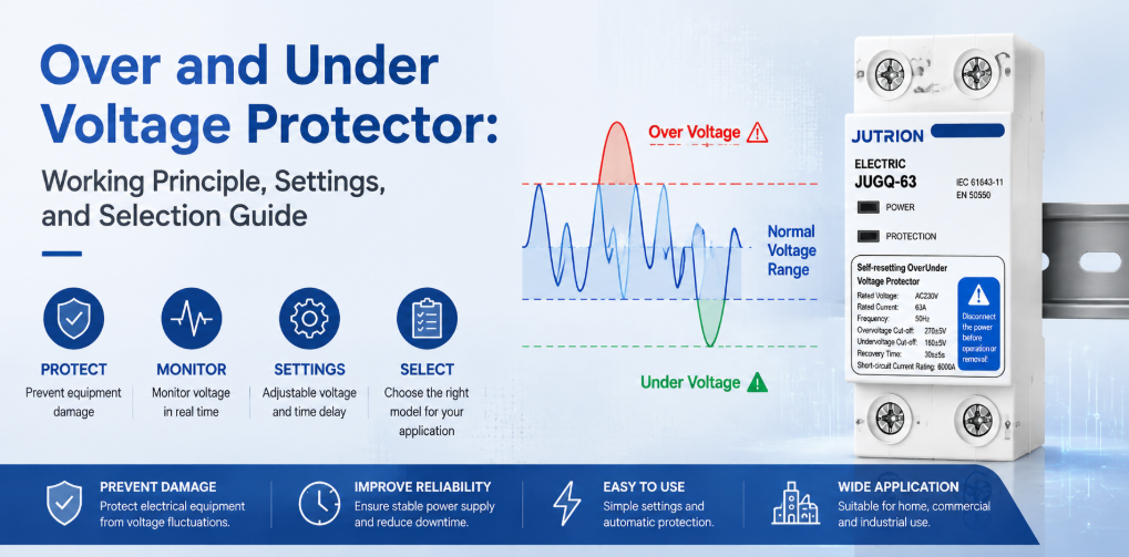
Принцип работы и руководство по выбору реле защиты от повышенного и пониженного напряженияКраткий ответ: что делает реле защиты от повышенного и пониженного напряжения?
Защитное устройство от перенапряжения и пониженного напряжения отключает цепь, когда напряжение питания выходит за выбранные пределы, затем подключает обратно после восстановления напряжения и истечения заданной задержки. Защищает от длительного перенапряжения, пониженного напряжения и провалов. Не заменяет SPD для импульсных перенапряжений, автоматический выключатель для перегрузок, RCD для утечки на землю или AVR при необходимости непрерывной коррекции напряжения.
“Защиту по напряжению” часто рассматривают как единую тему, но распределительный щит может сталкиваться с несколькими принципиально разными событиями. Переходный процесс, вызванный молнией, может длиться микросекунды. Проблема регулирования в сети или неправильно подключенный трансформатор могут удерживать напряжение выше нормального диапазона в течение нескольких минут. Перегруженный фидер может вызвать длительную просадку напряжения. Ослабленный или оборванный нейтральный провод может привести к тому, что некоторые однофазные нагрузки в трехфазной четырехпроводной системе окажутся под напряжением значительно выше номинального, а другие — ниже него.
Нет одного устройства, которое решало бы все эти задачи. SPD ограничивает короткие высокоэнергетические импульсы. Защитное устройство от перенапряжения и пониженного напряжения отключает нагрузку при выходе RMS напряжения за допустимые пределы. Автоматический выключатель прерывает ток перегрузки и короткого замыкания. RCD или RCBO реагируют на остаточный ток. Поэтому первым правилом выбора является не номинал тока или тип индикации, а соответствие устройства характеру нарушения.
Поэтому для сборщика щитов или дистрибьютора полезный вопрос не в том, присутствует ли “защита по напряжению”. Полезный вопрос в том, имеет ли каждое возмущение определенный метод измерения, реакцию переключения и правило восстановления.
Граница защиты: подберите правильное устройство для каждой проблемы с напряжением
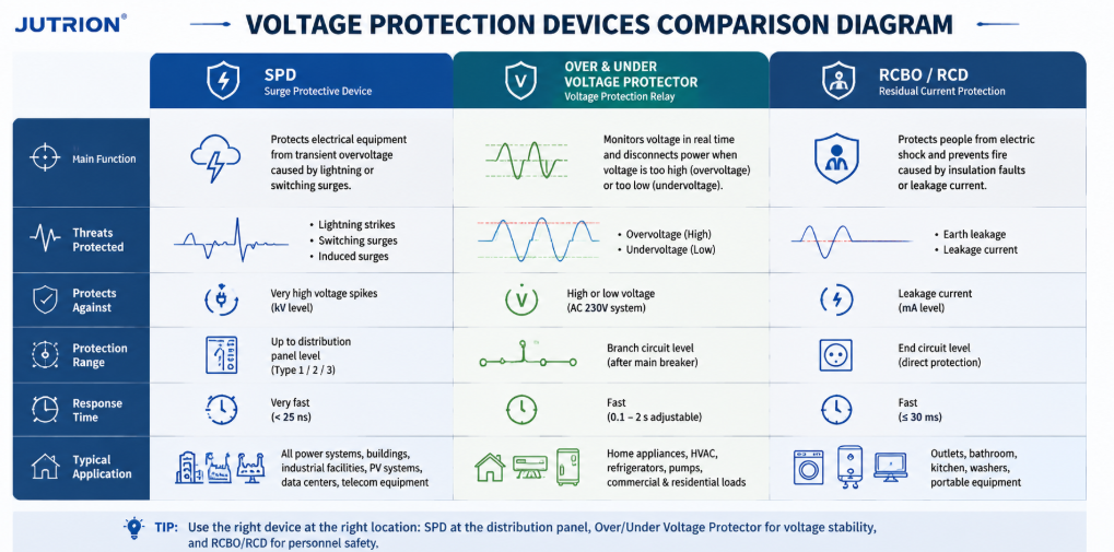
Схема сравнения устройств защиты напряжения, показывающая функции SPD, защитного устройства от перенапряжения и пониженного напряжения, а также RCBO и RCD| Возмущение | Типичная длительность | Основная реакция | Устройство, обычно отвечающее за защиту |
|---|---|---|---|
| Грозовой или коммутационный импульс | Микросекунды — миллисекунды | Ограничение и отвод энергии переходного процесса | Устройство защиты от перенапряжений (SPD) |
| Длительное перенапряжение | Секунды, минуты или дольше | Отключение затронутой нагрузки | Реле защиты от перенапряжения или реле контроля напряжения |
| Пониженное напряжение или просадка напряжения | Секунды, минуты или дольше | Отключение до перегрева, остановки или сбоя оборудования | Реле защиты от пониженного напряжения или реле контроля напряжения |
| Перегрузка или короткое замыкание | Зависит от величины повреждения | Прерывание чрезмерного тока | MCB или MCCB |
| Ток утечки на землю | Миллисекунды — длительное воздействие | Обнаружение дифференциального тока и отключение | RCCB или RCBO |
| Колебания напряжения, требующие непрерывной коррекции | Непрерывные или повторяющиеся | Повышение, понижение или стабилизация напряжения | Стабилизатор напряжения или AVR |
Хорошо спроектированная панель может содержать несколько таких устройств, поскольку они работают на разных временных масштабах и контролируют разные электрические параметры. Установка SPD не отменяет необходимость защиты от длительного перенапряжения. Добавление защитного устройства напряжения не увеличивает отключающую способность малого автоматического выключателя. Правильная координация — это сумма, а не конкуренция.
Почему автоматический выключатель может не сработать при плохом напряжении
Обычный автоматический выключатель реагирует в основном на ток. Если напряжение питания растёт, но подключённое оборудование не сразу потребляет ток, достаточный для пересечения времятоковой характеристики выключателя, выключатель может оставаться замкнутым, в то время как чувствительная электроника испытывает разрушительное электрическое воздействие. При пониженном напряжении двигатель может потреблять больший ток для создания требуемого момента, но точная реакция зависит от двигателя, нагрузки и контроллера. Выключатель в итоге может сработать, однако он не предназначен для контроля того, является ли напряжение питания допустимым.
Защитное устройство по напряжению закрывает это слепое пятно, измеряя напряжение напрямую. Если в защитное устройство также встроена защита от сверхтока, эта функция всё равно должна быть согласована с вышестоящим устройством защиты от короткого замыкания. Вышестоящий MCB или MCCB остаётся необходимым для безопасного отключения повреждения.
Где устанавливается защитное устройство от повышенного и пониженного напряжения
Защитное устройство от повышенного и пониженного напряжения — это устройство контроля и коммутации, используемое между источником питания и нагрузкой или нижестоящей распределительной цепью. Его измерительная цепь отслеживает входящее напряжение. Контроллер сравнивает измеренное значение с настроенными верхним и нижним порогами. Если напряжение остаётся за пределами допустимого окна в течение соответствующего времени срабатывания, устройство размыкает свои коммутационные контакты или подаёт команду внешнему контактору на размыкание.
Модели с автоматическим повторным включением продолжают контролировать источник, пока нагрузка отключена. Как только напряжение возвращается в пределы восстановления, контроллер запускает задержку повторного подключения. Нагрузка восстанавливается только в том случае, если питание остаётся допустимым в течение всей этой задержки. Это предотвращает быстрое циклическое включение-выключение и даёт компрессорам, холодильным системам, электронным источникам питания и другому оборудованию время стабилизироваться перед повторным пуском.
Распространённые названия включают: защитное устройство от повышенного и пониженного напряжения, устройство защиты по напряжению, автоматический переключатель напряжения, самовосстанавливающееся защитное устройство по напряжению, защитное устройство с автоматическим повторным включением и реле контроля напряжения. Эти термины пересекаются, но не всегда описывают одинаковые изделия. Некоторые устройства коммутируют нагрузку напрямую. Другие предоставляют релейные контакты для внешнего Контактор переменного тока. Некоторые контролируют только напряжение; другие добавляют измерение тока, защиту от сверхтока, контроль обрыва фазы или цифровой дисплей.
Что длительное повышенное и пониженное напряжение делают с оборудованием
Длительное повышенное напряжение
Длительное повышенное напряжение увеличивает диэлектрическую нагрузку и может ускорять старение изоляции. Конденсаторы источников питания, варисторы, LED-драйверы, управляющие трансформаторы и полупроводниковые входы могут работать ближе к своим проектным пределам или за их пределами. Мощность резистивного нагрева растёт примерно пропорционально квадрату напряжения при постоянном сопротивлении, поэтому даже умеренное повышение напряжения может привести к значительно большему росту тепла. Результатом может быть немедленный отказ, ложное отключение или сокращение срока службы, которое трудно связать с исходным событием в сети.
Возможные причины включают неправильные отводы трансформатора, неисправности регулятора, ошибки в электропроводке, проблемы с AVR генератора, сброс нагрузки, повреждения нейтрали и питание, не подходящее для подключённого оборудования. Защитное устройство по напряжению не может устранить причину, но оно может отключить нагрузку, пока такое состояние существует.
Пониженное напряжение и просадки сети
Пониженное напряжение — это не просто “меньше мощности”. Двигатели могут не разгоняться или останавливаться под нагрузкой. Контакторы могут дребезжать или отключаться. Реле и контроллеры могут непредсказуемо сбрасываться. Электронные нагрузки с постоянной мощностью могут пытаться потреблять больший ток при снижении напряжения, увеличивая тепловую нагрузку на проводники и компоненты. Компрессоры холодильных установок особенно чувствительны к повторным перезапускам до выравнивания давления.
Правильная реакция зависит от нагрузки. Некоторое электронное оборудование имеет широкий диапазон входного напряжения и может пережить умеренный провал. Насос с электроприводом может требовать быстрого отключения. Критическая система управления может требовать ИБП, а не простого отключения. Поэтому порог срабатывания и задержка защитного устройства должны выбираться исходя из требований оборудования, а не копироваться вслепую с другой панели.
Обрыв нейтрали: критическая опасность в трехфазной четырехпроводной системе
В сбалансированной трехфазной четырехпроводной системе нагрузки между фазой и нейтралью схожи, и ток нейтрали может быть относительно небольшим. Реальные установки редко бывают идеально сбалансированы. Если нейтральный проводник ослаблен или разомкнут выше по цепи относительно несимметричных однофазных нагрузок, нейтральная точка может сместиться. Тогда напряжения между фазой и нейтралью определяются сопротивлениями нагрузок, а не остаются зафиксированными на своих номинальных значениях.
Одна группа нагрузок может получить серьезное перенапряжение, а другая — пониженное напряжение, даже если напряжение между фазами по-прежнему выглядит нормальным. Это делает событие обрыва нейтрали особенно опасным в смешанных коммерческих, жилых, телекоммуникационных и легкопромышленных панелях. Повреждение оборудования может произойти до того, как обычное устройство максимальной токовой защиты обнаружит неисправность, достаточную для срабатывания.
Схема контроля трехфазного напряжения должна оценивать каждую соответствующую фазу и, если этого требует применение, напряжения между фазой и нейтралью. Обрыв фазы, несимметрия фаз и целостность нейтрали должны учитываться явно. Одиночное измерение на одной фазе не заменяет полный контроль трехфазной четырехпроводной нагрузки.
Примечание по проектированию: защитное реле напряжения снижает воздействие на оборудование; оно не делает неисправную нейтраль безопасной. Ослабленные соединения, заниженное сечение проводников, коррозия и повреждения в вышестоящей сети должны быть обнаружены и устранены.
Однофазная и трехфазная защита — это разные решения
Однофазное защитное устройство обычно принимает одно центральное решение: находится ли измеренное линейно-нейтральное напряжение в пределах допустимого рабочего окна? Это звучит просто, но установка должна определить номинальное напряжение, ток, проходящий через устройство, нужно ли переключать один или два проводника, и как нейтраль обрабатывается в соответствии с местной системой заземления. Изделие, маркированное для номинальной цепи 230 В, нельзя выбирать только по маркировке тока 63 A.
Однофазные применения обычно включают квартиры, небольшие магазины, телекоммуникационные шкафы, холодильные цепи, осветительные панели и отдельные машины. Их нагрузки могут реагировать на одно и то же событие совершенно по-разному. Светодиодный драйвер может выдержать короткий провал, из-за которого катушка контактора отпустит. Холодильник может пережить провал, но быть поврежден немедленным повторным пуском. Поэтому правильно подобранное защитное устройство сочетает правильное окно напряжения с задержкой восстановления, подходящей для наиболее чувствительной к повторному пуску нагрузки ниже по цепи.
Что может потребоваться контролировать трехфазному защитному устройству
Трехфазная защита — это не просто три копии однофазного измерения. Функция контроля может требовать оценки напряжения между фазами, напряжения между фазой и нейтралью, обрыва фазы, чередования фаз и несимметрии напряжений. Какие функции важны, зависит от нагрузки и схемы проводников. Трехпроводной фидер двигателя имеет иной профиль риска, чем четырехпроводной распределительный щит, питающий десятки несимметричных однофазных цепей.
- Обрыв фазы означает, что одна питающая фаза отсутствует или пропала. Работающий трехфазный двигатель может продолжать работать с повышенным током в оставшихся фазах, сниженным моментом и быстрым нагревом. Защитное устройство, предназначенное для работы с двигателем, должно обнаруживать это состояние или работать совместно с реле защиты двигателя, которое это делает.
- Чередование фаз определяет направление вращения многих трехфазных двигателей. Обычно это важно при пусконаладке или после изменений в подводящей проводке. Функция защиты от повышенного и пониженного напряжения не подразумевает автоматически защиту по чередованию фаз, поэтому требуемая функция должна быть указана явно.
- Несимметрия напряжений описывает неравенство фазных напряжений. Кажущаяся незначительной несимметрия напряжений может вызвать значительно большую несимметрию токов в двигателе. Допустимый предел должен определяться исходя из конструкции двигателя и системы. Устройство, которое срабатывает только при широких порогах повышенного и пониженного напряжения, может не обеспечивать специальный контроль несимметрии.
- Смещение нейтрали имеет центральное значение, когда нагрузки между фазой и нейтралью неравны. Если трехфазное устройство измеряет только междуфазные значения, оно может не заметить опасное разделение напряжений между фазой и нейтралью, вызванное обрывом нейтрали. Сборщикам панелей следует точно подтверждать, какие именно напряжения измеряет выбранное устройство, а не полагаться на слова “трехфазный” в описании.
| Система и нагрузка | Измерения, которым следует отдать приоритет | Типовой подход к коммутации |
|---|---|---|
| 230 В однофазное конечное распределение | Повышенное и пониженное напряжение между фазой и нейтралью | Прямая коммутация, когда номинальные параметры и координация это допускают |
| 400 В трёхфазная линия питания двигателя | Междуфазное напряжение, обрыв фазы, несимметрия и, возможно, чередование фаз | Контролирующее устройство, управляющее контактором с номиналом для двигателя |
| 400/230 В четырёхпроводная панель с смешанной нагрузкой | Все соответствующие напряжения между фазой и нейтралью, обрыв фазы и смещение, связанное с нейтралью | Многополюсное отключение, выбранное в соответствии со схемой заземления |
| Распределение с резервом от генератора | Напряжение на активном источнике, а также частота и состояние системы переключения, где это требуется | Согласование с контроллером генератора и оборудованием переключения |
Это различие также влияет на сравнение изделий. Компактный однофазный самовозвратный защитный аппарат может быть отличным устройством для потребительского щита, но неподходящей архитектурой управления для большого щита трехфазного двигателя. И наоборот, сложное реле контроля фаз в сборе с контактором может добавить стоимость и занять место в панели, которые стандартизированной однофазной цепи не нужны. Правильный выбор — это наименьшая архитектура, которая контролирует все условия по напряжению, способные повредить фактическую нагрузку.
Как работает автоматически повторно включающийся защитный аппарат по напряжению
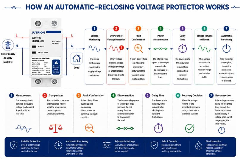
Принципиальная схема работы автоматически повторно включающегося защитного аппарата по напряжению- Измерение: измерительная цепь снимает напряжение питания и, на соответствующих моделях, ток или дополнительные параметры фаз.
- Сравнение: контроллер сравнивает измеренные значения с запрограммированными пределами повышенного и пониженного напряжения.
- Подтверждение неисправности: фильтрация или задержка срабатывания отбрасывает незначительные помехи и очень короткие возмущения, которые не должны отключать нагрузку.
- Отключение: внутренние контакты размыкаются, или выходное реле снимает питание катушки с внешнего контактора.
- Продолжающийся контроль: источник остается под наблюдением, пока нагрузка ниже по цепи изолирована.
- Решение о восстановлении: когда напряжение возвращается в допустимую полосу восстановления, запускается таймер.
- Повторное подключение: если источник остаётся стабильным в течение всей задержки, устройство автоматически повторно подключается. Если напряжение снова становится неприемлемым, таймер сбрасывается.
Микропроцессорная цифровая выборка делает регулируемые пороги, временные задержки, дисплеи и логику состояний практичными в компактном устройстве для DIN-рейки. Фильтрация важна в электрически шумных установках, поскольку ложные срабатывания могут быть почти столь же разрушительными, как само событие напряжения. Фильтр и время подтверждения должны отклонять незначительные отклонения, не маскируя устойчивое состояние, которое может повредить нагрузку.
Почему уровень срабатывания, уровень восстановления и задержка должны работать вместе
Защитное устройство не принимает одно решение о напряжении. Обычно оно принимает как минимум три связанных решения: когда питание стало неприемлемым, когда оно восстановилось достаточно, чтобы снова считаться приемлемым, и как долго оно должно оставаться стабильным перед повторным подключением нагрузки. Эти значения образуют единую стратегию управления, и их следует рассматривать вместе.
Если уровни срабатывания и восстановления слишком близки, питание, колеблющееся вблизи границы, может вызывать повторные отключения и включения. Отдельное значение восстановления создаёт гистерезис: после срабатывания по пониженному напряжению, например, напряжение должно подняться до более здорового уровня, прежде чем повторное подключение станет возможным. Затем таймер повторного подключения подтверждает, что восстановление является стабильным, а не кратковременным.
Правильная выдержка времени следует за нагрузкой. Резистивный нагреватель может допускать относительно быстрое возвращение. Компрессор холодильной установки может нуждаться в более длительной паузе перед перезапуском. Панель с несколькими двигателями может нуждаться в поэтапном повторном подключении, чтобы их совокупный пусковой ток не просадил питание ниже порога снова. Вот почему регулируемая задержка является инженерным параметром, а не просто удобной функцией.
Для регулируемой модели запишите утверждённые значения срабатывания, восстановления и задержки как один набор настроек. Изменение только верхнего или нижнего порога может изменить предполагаемый гистерезис и поведение при перезапуске. Для модели с заводской калибровкой убедитесь, что предустановленное окно управления соответствует целевому питанию и подключённому оборудованию, прежде чем стандартизировать его для всего проекта.
Как выбрать защиту от перенапряжения и пониженного напряжения
Подтвердите напряжение системы, частоту и фазовое исполнение
Начинайте с фактической системы распределения, а не с заголовка каталога. Запишите номинальное фазо-нейтральное и фазо-фазное напряжение, частоту, однофазную или трёхфазную схему, количество проводников, использование нейтрали и допустимые отклонения питания. IEC 60038 предоставляет стандартные эталонные напряжения, включая распространённые низковольтные системы 230/400 В, но окончательные требования определяются проектной спецификацией и местными правилами электроснабжения.
Для трёхфазных нагрузок определите, должно ли устройство также контролировать потерю фазы, чередование фаз, несимметрию и смещение фаза-нейтраль. Для панели, содержащей множество однофазных нагрузок, мониторинг, связанный с нейтралью, может быть важнее, чем для сбалансированной трёхпроводной нагрузки двигателя.
Определите нагрузку, которая будет отключена
Перечислите подключённую нагрузку, максимальный спрос, непрерывный ток, пусковой ток и тип нагрузки. Цепь с резистивной нагрузкой 40 A, линия питания двигателя 40 A и банк импульсных источников питания 40 A предъявляют разные требования к коммутационной нагрузке. Определите компрессоры, насосы, трансформаторы, ёмкостные входы и оборудование с внутренними защитами от пониженного напряжения или перезапуска.
Не выбирайте исключительно по номиналу служебного автоматического выключателя. Защитное устройство должно подходить для тока, который оно пропускает, и коммутационной нагрузки, которую оно выполняет, в то время как вышестоящее защитное устройство должно обеспечивать требуемую защиту от короткого замыкания. Ёмкость клемм, размер проводников, температура окружающей среды и вентиляция корпуса также имеют значение.
Решите между прямым переключением и внешним контактором
Компактное защитное устройство может напрямую коммутировать соответствующим образом рассчитанную нагрузку, когда его контактный номинал, режим использования и координация с ожидаемым током КЗ подходят. Для более крупной панели, нагрузки с преобладанием двигателей, частых операций или тока, превышающего возможности прямого переключения защитного устройства, используйте реле контроля или защитное устройство для управления правильно выбранным контактором. Это разделяет логику измерения и коммутационную нагрузку силовой цепи.
При использовании внешнего контактора проверьте напряжение катушки, категорию применения контактора, вспомогательные контакты, защиту цепи управления и отказобезопасное поведение. Решите, что происходит после потери питания и разрешён ли автоматический перезапуск оценкой рисков процесса.
Установите пределы перенапряжения и пониженного напряжения
Окно срабатывания должно быть достаточно широким, чтобы допускать нормальные колебания питания, и достаточно узким, чтобы защитить подключённое оборудование. Используйте наиболее строгое достоверное требование от производителя оборудования, спецификации проекта и местных правил установки. Значение, увиденное в общем примере, не является автоматически подходящим для двигателей, холодильного оборудования, медицинского оборудования, телекоммуникационных источников питания или технологических систем управления.
| Настройка | Назначение | Вопрос выбора |
|---|---|---|
| Уровень срабатывания по перенапряжению | Определяет точку отключения по высокому напряжению | Какое устойчивое входное напряжение может выдержать наиболее чувствительное подключённое оборудование? |
| Уровень срабатывания по пониженному напряжению | Определяет точку отключения по низкому напряжению | При каком напряжении двигатели, контакторы или источники питания больше не могут работать безопасно? |
| Задержка срабатывания | Отклоняет кратковременные отклонения | Какие короткие возмущения нагрузка может перенести без вреда? |
| Уровень восстановления | Определяет, когда напряжение снова становится приемлемым | Обеспечен ли достаточный гистерезис для предотвращения повторных переключений? |
| Задержка повторного включения | Ожидает стабильного питания и безопасного перезапуска | Нужны ли нагрузке секунды или минуты перед перезапуском? |
Выберите задержку повторного подключения для нагрузки
Короткая задержка может быстро восстановить освещение или некритичные резистивные нагрузки. Компрессоры холодильного и климатического оборудования часто требуют более длительной задержки для выравнивания давления и предотвращения жёсткого перезапуска. Одновременное повторное подключение нескольких нагрузок может создать новую просадку напряжения, поэтому крупные установки могут требовать поэтапного перезапуска, а не одного общего таймера.
Автоматическое повторное включение удобно, но оно подходит не везде. Механизмы, которые могут неожиданно прийти в движение, могут требовать ручного сброса, контроллера безопасности или другой контролируемой последовательности перезапуска. Восстановление напряжения никогда не должно обходить требования безопасности машин.
Проверьте полюса, схему нейтрали и изоляцию
Выберите количество полюсов исходя из системы заземления и требований установки. Коммутация нейтрали не является универсальным правилом. В одних системах она требуется; в других может быть запрещена или не нужна. Выбор должен быть согласован с вышестоящим заземлением, схемами переключения источников и местными нормами. Никогда не рассматривайте двухполюсный или четырёхполюсный вариант из каталога как доказательство того, что он подходит для любой сети.
Проверьте координацию и условия установки
Подтвердите номинальный ток, рабочее напряжение, частоту, ёмкость клемм, способ монтажа, диапазон температур, защиту оболочки и требуемое вышестоящее защитное устройство. Проверьте координацию по короткому замыканию, а не предполагайте, что небольшое модульное устройство может отключить любой доступный ток КЗ. Проверьте момент затяжки проводников и обеспечьте рабочее пространство и вентиляцию согласно инструкциям производителя.
IEC 60364-4-44 рассматривает защиту низковольтных установок от нарушений напряжения и электромагнитных помех. Применяйте редакцию и национальное принятие, требуемые рынком назначения; не используйте ссылку на IEC как замену полного проектирования.
Стандарты и вопросы экспортных рынков, которые меняют спецификацию
Ссылки на стандарты должны определять инженерные границы, а не украшать описание продукта. IEC 60364-4-44:2024 рассматривает защиту низковольтных установок от нарушений напряжения и электромагнитных помех. Это документ уровня установки: он помогает проектировщикам учитывать последствия помех в электроустановке, но он не является типовым техническим паспортом и сам по себе не доказывает, что конкретный защитный аппарат подходит для проекта.
IEC 60038 определяет стандартные значения напряжения, используемые в качестве ориентиров для оборудования и систем электроснабжения. Номинальное напряжение является отправной точкой для настройки защитного устройства, но не единственным критерием. Нормальные колебания напряжения, допустимый диапазон входных параметров подключённого оборудования, региональные требования к качеству электроснабжения и логика восстановления влияют на допустимый рабочий диапазон.
Стандарт продукции, кодекс монтажа и качество электроснабжения
Эти три уровня отвечают на разные вопросы. Стандарт продукции описывает классификацию, конструкцию и испытания устройства. Кодекс монтажа определяет, как оборудование выбирается и устанавливается в здании или на предприятии. Документ по качеству электроснабжения описывает характеристики, ожидаемые в точке подключения. Покупатель не должен заменять один уровень другим. Например, знание, что страна использует номинальную систему 230/400 В, не определяет необходимость переключения нейтрали, а ссылка на кодекс монтажа не устанавливает способность конкретного изделия к отключению короткого замыкания.
Рынок назначения может также использовать национальное принятие документа IEC с местными изменениями. Североамериканские проекты используют другие системные конвенции, списки продукции и правила монтажа. Знакомые функции — измерение, сравнение, отключение и задержка повторного включения — остаются понятными, но приемка продукции, переключение проводников, маркировка корпусов и координация должны проверяться в региональном контексте.
Заявления о сертификации должны точно соответствовать конкретной модели
Термины, такие как IEC, UL и CB, должны сопровождаться документацией, которая идентифицирует соответствующий стандарт, модель или серию, электрические характеристики и орган, выдавший документ. Общая декларация возможностей завода не является сертификатом, охватывающим все варианты. Импортеры и сборщики щитов должны сопоставлять ссылку на документ с заказанным каталожным номером и требованиями рынка назначения.
Та же дисциплина применяется к номинальному току и заявленным характеристикам защиты. Если серия включает несколько вариантов по току или числу полюсов, доказательства для одного варианта не должны автоматически распространяться на все остальные. Если защитное устройство включает функцию защиты от перегрузки по току, уточните его рабочую характеристику и связь с upstream автоматическим выключателем. «Перегрузка» на дисплее не означает автоматически, что устройство обеспечивает прерывание короткого замыкания, ожидаемое от MCB или MCCB.
Компактная экспортная спецификация
Перед сравнением моделей сформулируйте условия проекта в одной строке: рынок назначения; номинальное напряжение и частота; схема подключения фазы и нейтрали; непрерывный ток и тип нагрузки; пределы перенапряжения и пониженного напряжения; время срабатывания и восстановления; количество переключаемых полюсов; прямое переключение или управление контактором; upstream защита; условия монтажа и окружающей среды; и требуемые документы о соответствии. Эта строка быстро выявляет несоответствия и предотвращает ошибочное приравнивание трёх продуктов с одинаковой маркировкой тока на передней панели.
Для дистрибьюторов, обслуживающих несколько стран, регулируемые модели могут снизить фрагментацию запасов, но только при контролируемой настройке. Диапазон настройки полезен, если монтажный персонал знает утверждённые значения и предотвращены несанкционированные изменения. Для одного стабильного рынка и повторяемой конструкции щита заводская калибровка порогов может обеспечить более стабильный монтаж и упростить обучение. Решение об экспорте, таким образом, частично электрическое и частично операционное.
Выбор между тремя сериями JUTRION
JUTRION предлагает три реле контроля повышенного и пониженного напряжения серии для различных приоритетов щитов и закупок. Выбор продукта должен подтверждаться в соответствии с требуемыми электрическими характеристиками и проектной документацией.
| Критерий выбора | JRGQ-63 | JQGQ-63 | JUGQ-63 |
|---|---|---|---|
| Позиционирование серии | Флагманская регулируемая модель | Компактная цифровая модель | Экономичная модель с заводскими настройками |
| Дисплей и мониторинг | Двойной цифровой дисплей с мониторингом напряжения и тока в реальном времени | Компактный цифровой дисплей с интеллектуальным мониторингом | Упрощённый интерфейс для использования plug-and-play |
| Настройки напряжения | Регулируемые параметры перенапряжения и пониженного напряжения → Регулируемые параметры перенапряжения и пониженного напряжения | Регулируемые пороги | Заводская калибровка порогов |
| Дополнительная функция указана на публичной странице | Защита от перегрузки по току и автоматическое повторное включение | Автоматическое повторное включение | Автоматическое повторное включение |
| Формат установки | Модульный формат на DIN-рейку 35 мм | Компактный формат на DIN-рейку | Оптимизированный формат на DIN-рейку |
| Оптимальное применение | Проекты, требующие видимых рабочих данных и широкого контроля параметров | Распределительные щиты с высокой плотностью монтажа, где важна экономия места | Стандартизированные, массовые применения с простой установкой |
| Подтвердите по техническому описанию заказанной модели | Номинальное напряжение, ток, количество полюсов, точные диапазоны настройки и задержек, клеммы, температурные ограничения, габариты, режим коммутации, защита по цепи питания и документы о соответствии, специфичные для модели | ||
Выбирайте JRGQ-63, когда важны регулировка, информация о токе и более полный интерфейс на устройстве. Выбирайте JQGQ-63, когда требуется регулируемая цифровая защита, но плотность монтажа на панели является главным ограничением. Выбирайте JUGQ-63, когда требуемое окно защиты соответствует заводской калибровке, а важнее согласованность, простота и экономия при больших объемах, чем настройка в полевых условиях.
Покупатель не должен сравнивать только цену за единицу. Необходимо нормализовать номинальное напряжение, ток, количество полюсов, диапазон регулировки, логику срабатывания и восстановления, диапазон задержек, метод коммутации, отображение, функцию защиты от перегрузки, клеммы, сертификаты, упаковку и возможность кастомизации. Два устройства, описываемые как «автоматические защитные устройства на 63 A», могут иметь существенно разные функции.
Примените логику выбора к четырём сценариям панелей
Коммерческий распределительный щит на нестабильной сети
Небольшое коммерческое предприятие испытывает длительные вечерние провалы напряжения и периодические перенапряжения при малой нагрузке. Щит питается освещением, кассовым оборудованием, холодильным оборудованием и офисной электроникой. Защитное устройство может отключать выбранные цепи нагрузки вне допустимого окна. Поскольку холодильное оборудование требует иной порядок перезапуска, чем освещение и офисные нагрузки, проектировщик может разделить нагрузки или использовать отдельное управление, чтобы единая задержка повторного включения не нарушала ни непрерывность питания, ни защиту компрессора.
OEM-панель для насосов или систем ОВК
Нагрузка включает двигатели с высоким пусковым током и цепь управления, чувствительную к пониженному напряжению. Прямое переключение через компактный защитный прибор может быть не предпочтительной архитектурой. Защитное устройство может контролировать источник и управлять AC-контактором, выбранным под нагрузку двигателя. Проект управления должен предотвращать небезопасный автоматический перезапуск и координировать поведение при пониженном напряжении с реле защиты двигателя и контроллером процесса.
Трёхфазная панель с множеством однофазных нагрузок
Панель 400/230 В распределяет различные однофазные цепи по трём фазам. Неравномерная нагрузка делает открытый нейтраль опасным. Стратегия мониторинга должна контролировать все соответствующие фазо-нейтральные напряжения и отключать затронутый участок распределения при отклонении значений за допустимые пределы. Процедуры обслуживания должны предусматривать поиск и устранение неисправности нейтрали.
Стандартизованный потребительский блок с большим объемом производства
OEM выпускает множество панелей для одного рынка со стабильной, заранее определённой спецификацией защиты. Настройка в полевых условиях не требуется и может привести к несогласованности при вводе в эксплуатацию. Заводская калиброванная модель с автоматическим повторным включением, такая как JUGQ-63, может обеспечить более простое решение при условии соответствия номинального напряжения, тока, порогов, количества полюсов и сертификатов проекту.
Установка, ввод в эксплуатацию и диагностика системы защиты
Контрольный список установки и ввода в эксплуатацию
- Убедитесь, что источник изолирован, и соблюдайте процедуру блокировки проекта.
- Проверьте номинальное напряжение, частоту, расположение фаз и маркировку проводников.
- Уточните, переключает ли защитное устройство нагрузку напрямую или управляет контактором.
- Проверьте защиту от короткого замыкания и перегрузки по цепи питания.
- Соответствие сечений проводников и номинала клемм; затяните с указанным моментом.
- Запрограммируйте пороги и задержки согласно утверждённому графику настроек.
- Проверьте работу при перенапряжении и пониженном напряжении с помощью подходящего испытательного оборудования, а не создавая опасные условия питания.
- Проверьте индикацию срабатывания, состояние контактов и таймер повторного включения.
- Убедитесь, что двигатели и оборудование перезапускаются безопасно.
- Занесите в протокол настройки, модель, серийный или партийный номер и результаты ввода в эксплуатацию.
После ввода в эксплуатацию исследуйте частые срабатывания, а не просто расширяйте пороги. Повторные срабатывания могут указывать на неплотный нейтральный провод, недостаточное сечение питающего кабеля, перегрузку трансформатора, проблему с управлением генератором или качество питания. Защитное устройство часто является лишь индикатором, а не причиной.
Распространённые ошибки при выборе и установке
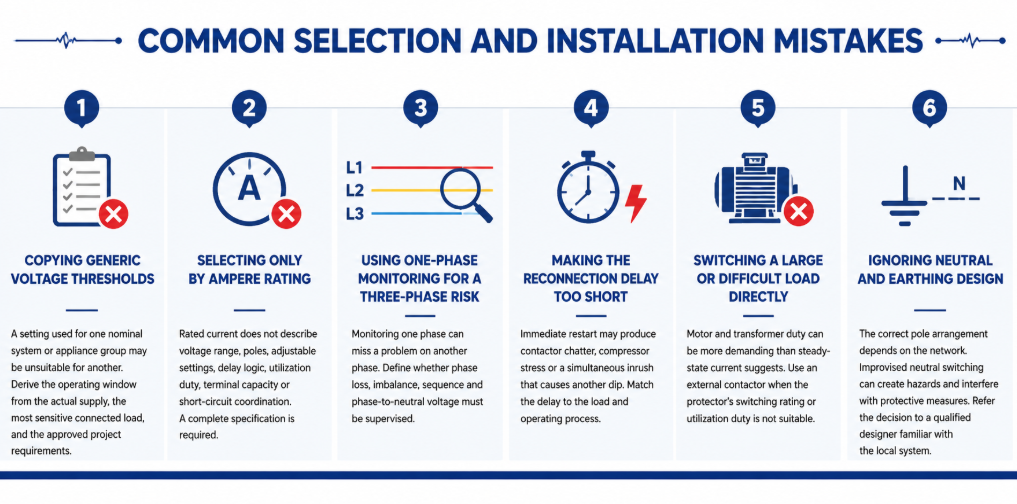
Распространённые ошибки при выборе и установке автоматического повторного включения защитного устройства напряжения- Копирование универсальных порогов напряжения: Настройка, используемая для одной номинальной системы или группы приборов, может быть неприемлема для другой. Определяйте рабочее окно исходя из фактического питания, самой чувствительной подключённой нагрузки и утверждённых требований проекта.
- Выбор только по номинальному току: Номинальный ток не описывает диапазон напряжения, количество полюсов, регулируемые настройки, логику задержек, режим эксплуатации, ёмкость клемм или координацию при коротком замыкании. Требуется полная спецификация.
- Использование однофазного мониторинга для трёхфазного риска: Мониторинг одной фазы может пропустить проблему в другой фазе. Определите, необходимо ли контролировать пропадание фазы, дисбаланс, последовательность и фазо-нейтральное напряжение.
- Слишком короткая задержка повторного включения: Немедленный перезапуск может вызвать дребезг контактора, стресс компрессора или одновременный пусковой ток, вызывающий очередной провал напряжения. Подбирайте задержку в соответствии с нагрузкой и технологическим процессом.
- Прямое включение большой или сложной нагрузки: Нагрузка электродвигателей и трансформаторов может быть более требовательной, чем указывает ток в установившемся режиме. Используйте внешний контактор, если номинал коммутации или режим эксплуатации защитного устройства не подходят.
- Игнорирование проектирования нейтрали и заземления: Правильное расположение полюсов зависит от сети. Самодельное переключение нейтрали может создавать опасности и мешать защитным мерам. Передайте решение квалифицированному проектировщику, знакомому с местной системой.
Техническое обслуживание и устранение неисправностей в эксплуатации
Защитное устройство напряжения обычно требует минимального регулярного вмешательства, но его следует включать в план осмотра щита. Проверяйте наличие обесцвечивания, тепловых повреждений, ослабленных клемм, скопления пыли, трещин в корпусе и аномальных значений на дисплее. Сравнивайте отображаемое напряжение с показаниями калиброванного прибора при сомнительных показаниях. Тепловизионное обследование под типовой нагрузкой может выявить плохое соединение клемм, хотя не заменяет проверку момента затяжки под безопасными изолированными условиями.
Ведите учет срабатываний, если важна непрерывность работы. Время, отображаемое напряжение, затронутая фаза, подключенная нагрузка и время восстановления помогут отличить проблему качества питания от падения напряжения, связанного с нагрузкой. Несколько срабатываний в одно и то же время производства могут указывать на перегрузку питающей линии. Случайные высокие и низкие показания на однофазных цепях могут свидетельствовать о проблемах с нейтралью. Срабатывания только при работе генератора могут указывать на настройки AVR, изменение частоты или плохое согласование генератора и нагрузки.
| Наблюдаемый симптом | Возможные причины для расследования | Полезные проверки |
|---|---|---|
| Срабатывания сразу после установки | Неправильная модель с номинальным напряжением, ошибка подключения, порог установлен слишком близко к нормальному напряжению питания | Проверьте модель, подключения линия/нейтраль, измеренное напряжение и график настроек |
| Повторяющийся цикл срабатывания и восстановления | Недостаточный гистерезис, нестабильное питание, пусковой ток при перезапуске вызывает новое падение напряжения | Запишите напряжение при перезапуске; проверьте уровень восстановления и задержку |
| Дисплей включен, но нагрузка не работает | Активная неисправность, задержка еще идет, поврежденный контакт, проблема с внешним контактором/управлением | Считайте индикацию состояния и проверьте цепь управления согласно руководству |
| Одна фаза показывает аномальное напряжение | Ослабленная фаза или нейтраль, дисбаланс фаз, неисправность подключения выше по цепи | Безопасно отключите и осмотрите все проводники; измерьте каждую соответствующую фазу |
| Высокая температура клеммы | Ослабленное соединение, неподходящий проводник, перегрузка, плохая вентиляция корпуса | Измерьте ток нагрузки, проверьте подготовку проводника и подтвердите заданный момент затяжки |
Не сбрасывайте и не обходите защитное устройство повторно до выяснения причины срабатывания. Обход защиты устраняет защиту в момент, когда система может демонстрировать реальную неисправность. Если устройство отключало серьёзную или повторяющуюся нагрузку, осмотрите его контакты и подключённые проводники согласно инструкциям производителя по обслуживанию. Замените устройство, если обнаружены термические повреждения, ненадёжное срабатывание или показания вне заявленной точности, вместо попыток несанкционированного ремонта.
Настройки также должны контролироваться. Для регулируемых моделей фиксируйте утвержденные значения при вводе в эксплуатацию и ограничивайте несанкционированные изменения. При добавлении оборудования, изменении питания или экспорте щита на рынок с другим номинальным напряжением пересмотрите весь график настроек. Защитное устройство, правильно настроенное для исходной установки, может стать неподходящим после модификации системы.
Часто задаваемые вопросы
Почему защитное устройство выжидает перед повторным подключением нагрузки?
Задержка подтверждает, что напряжение восстановилось, и предотвращает быстрое циклирование. Она также может обеспечить время перезапуска для компрессоров и снизить вероятность того, что одновременный пусковой ток снова снизит питание.
Может ли он защитить от потери нейтрали?
Оно может снизить воздействие, если контролирует затронутые фазно-нейтральные напряжения и отключается, когда они выходят за допустимый диапазон. Оно не может устранить повреждение нейтрали, и схема контроля должна охватывать все соответствующие фазы.
Является ли защита от перенапряжения/пониженного напряжения тем же самым, что и стабилизатор напряжения?
Нет. Протектор отключает нагрузку. Стабилизатор или АВР пытается скорректировать выходное напряжение, продолжая его подавать. Выбирайте в зависимости от того, требуется ли отключение или непрерывное регулируемое питание.
Как выбрать номинальный ток?
Определите максимальный ток, который будет проходить через устройство, учитывайте режим нагрузки и пусковые токи, выберите подходящий номинал с необходимыми клеммами и условиями установки, согласуйте его с защитой по току выше по цепи. Используйте внешний контактор, если прямое включение неприемлемо.
Какую задержку повторного включения использовать?
Используйте требования производителя подключённого оборудования и оценку рисков технологического процесса. Общее освещение может допускать небольшую задержку; компрессоры и ступенчатые системы могут требовать значительно более длительного или последовательного восстановления питания.
Почему защитное устройство постоянно срабатывает?
Возможные причины включают реальные колебания питания, ослабленную нейтраль, перегрузку питающей линии, проблемы регулирования генератора, неправильные настройки, ошибки монтажа или несоответствие устройства и нагрузки. Измерьте и диагностируйте систему перед расширением порогов.
Выберите границы защиты до выбора варианта изделия
Защитное устройство от перенапряжения и пониженного напряжения наиболее эффективно при точном определении рабочего окна. Выбор становится практической последовательностью: установите номинальную систему и контролируемые проводники, изучите нагрузку, выберите прямое переключение или управление контактором, задайте согласованные значения срабатывания и восстановления, выберите безопасную задержку повторного включения, проверьте конфигурацию полюсов и нейтрали, протестируйте готовый щит в контролируемых условиях.
Для рекомендации модели отправьте в JUTRION номинальное напряжение и частоту, расположение фаз и нейтрали, ток и тип нагрузки, требуемые пороги и задержку, конфигурацию полюсов, защитное устройство выше по цепи, условия установки, рынок сертификации и количество заказа. Ассортимент JRGQ-63, JQGQ-63 и JUGQ-63 затем можно сравнить с фактическим проектом, а не выбирать только по номинальному току.
Технические ссылки
