

Over and Under Voltage Protector: Working Principle, Settings, and Selection Guide
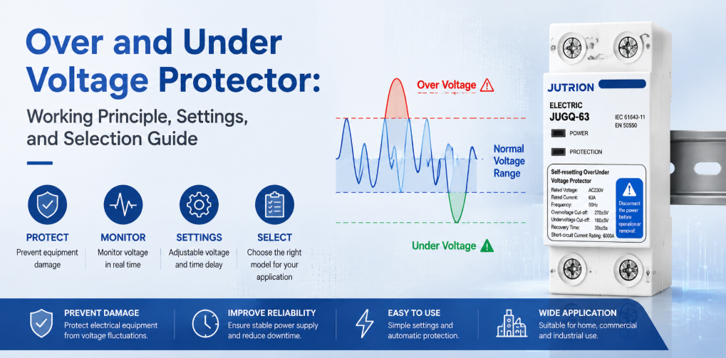
Over and under voltage protector working principle and selection guideQuick Answer: What Does an Over and Under Voltage Protector Do?
An over and under voltage protector disconnects a circuit when supply voltage remains above or below its selected limits, then reconnects after voltage recovers and a preset delay expires. It protects against sustained overvoltage, undervoltage and brownouts. It does not replace an SPD for transient surges, a circuit breaker for overcurrent, an RCD for earth leakage, or an AVR when continuous voltage correction is required.
“Voltage protection” is often treated as one subject, but a distribution panel can face several fundamentally different events. A lightning-induced transient may last microseconds. A utility regulation problem or an incorrectly tapped transformer may hold the supply above its normal range for minutes. An overloaded feeder may produce a long brownout. A loose or open neutral can drive some single-phase loads in a three-phase four-wire system far above nominal voltage while forcing others below it.
No single device handles all these conditions. A surge protective device limits short, high-energy transients. An over and under voltage protector disconnects the load when the RMS supply remains outside acceptable limits. A breaker interrupts overload and short-circuit current. An RCD or RCBO responds to residual current. The first selection rule is therefore not a current rating or a display type: it is matching the device to the disturbance.
For a panel builder or distributor, the useful question is therefore not whether “voltage protection” is present. The useful question is whether each disturbance has a defined sensing method, switching response and recovery rule.
The Protection Boundary: Match Each Voltage Problem to the Right Device
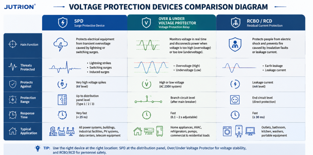
Voltage protection devices comparison diagram showing SPD, over under voltage protector, and RCBO RCD functions| Disturbance | Typical duration | Primary response | Device normally responsible |
|---|---|---|---|
| Lightning or switching surge | Microseconds to milliseconds | Clamp and divert transient energy | Surge protective device (SPD) |
| Sustained overvoltage | Seconds, minutes or longer | Disconnect the affected load | Overvoltage protector or voltage monitoring relay |
| Undervoltage or brownout | Seconds, minutes or longer | Disconnect before equipment overheats, stalls or malfunctions | Undervoltage protector or voltage monitoring relay |
| Overload or short circuit | Depends on fault magnitude | Interrupt excessive current | MCB or MCCB |
| Earth leakage | Milliseconds to sustained | Detect residual current and disconnect | RCCB or RCBO |
| Voltage fluctuation requiring continuous correction | Continuous or repeated | Boost, buck or regulate the voltage | Voltage stabilizer or AVR |
A well-designed panel may contain several of these devices because they work on different time scales and observe different electrical quantities. Installing an SPD does not make sustained overvoltage protection unnecessary. Adding a voltage protector does not increase the breaking capacity of a small circuit breaker. Correct coordination is additive, not competitive.
Why a Circuit Breaker May Not Trip on Bad Voltage
A conventional circuit breaker responds mainly to current. If supply voltage rises but the connected equipment does not immediately draw enough current to cross the breaker’s time-current curve, the breaker can remain closed while sensitive electronics experience damaging electrical stress. During undervoltage, a motor may draw more current to produce the required torque, but the exact response depends on the motor, load and controller. The breaker may eventually trip, yet it was not designed to supervise whether supply voltage is acceptable.
A voltage protector closes this blind spot by measuring voltage directly. Where overcurrent protection is also integrated into the protector, that function should still be coordinated with the upstream short-circuit protective device. The upstream MCB or MCCB remains essential for safe fault interruption.
Where the Over and Under Voltage Protector Fits
An over and under voltage protector is a monitoring and switching device used between a power source and a load or downstream distribution circuit. Its sensing circuit samples the incoming voltage. A controller compares the measured value with configured upper and lower thresholds. If voltage remains outside the permitted window for the applicable response time, the device opens its switching contacts or commands an external contactor to open.
Automatic-reclosing models continue monitoring the source while the load is disconnected. Once voltage returns within the recovery limits, the controller begins a reconnection delay. The load is restored only if the supply stays acceptable throughout that delay. This prevents rapid on-off cycling and gives compressors, refrigeration systems, electronic power supplies and other equipment time to settle before restart.
Common names include over/under voltage protector, voltage protection device, automatic voltage switcher, self-resetting voltage protector, automatic-reclosing protector and voltage monitoring relay. These terms overlap, but they do not always describe identical products. Some units switch a load directly. Others provide relay contacts for an external AC contactor. Some monitor only voltage; others add current measurement, overcurrent protection, phase-loss supervision or a digital display.
What Sustained Overvoltage and Undervoltage Do to Equipment
Sustained Overvoltage
Sustained overvoltage increases dielectric stress and can accelerate insulation aging. Power-supply capacitors, MOVs, LED drivers, control transformers and semiconductor inputs may run closer to or beyond their design limits. Resistive heating power rises approximately with the square of voltage when resistance is constant, so even a moderate voltage increase can produce a larger rise in heat. The result may be immediate failure, nuisance shutdown or shortened service life that is difficult to connect to the original supply event.
Possible causes include incorrect transformer taps, regulator faults, wiring errors, generator AVR problems, load rejection, neutral faults and a supply that is unsuitable for the connected equipment. A voltage protector cannot repair the cause, but it can isolate the load while the condition exists.
Undervoltage and Brownouts
Undervoltage is not simply “less power.” Motors can fail to accelerate or may stall under load. Contactors can chatter or drop out. Relays and controllers can reset unpredictably. Constant-power electronic loads may attempt to draw more current as voltage falls, increasing thermal stress on conductors and components. Refrigeration compressors are especially sensitive to repeated restarts before pressures equalize.
The correct response depends on the load. Some electronic equipment has a wide input range and can ride through a moderate dip. A motor-driven pump may need fast disconnection. A critical control system may require a UPS rather than simple disconnection. The protector’s threshold and delay must therefore be selected from equipment requirements, not copied blindly from another panel.
Lost Neutral: A Critical Three-Phase Four-Wire Hazard
In a balanced three-phase four-wire system, the phase-to-neutral loads are similar and the neutral current can be relatively low. Real installations are rarely perfectly balanced. If the neutral conductor becomes loose or open upstream of unequal single-phase loads, the neutral point can shift. The phase-to-neutral voltages are then determined by the load impedances instead of remaining fixed at their nominal values.
One group of loads may receive severe overvoltage while another receives undervoltage, even though the phase-to-phase voltage still appears normal. This makes an open-neutral event particularly dangerous in mixed commercial, residential, telecom and light-industrial panels. Equipment damage can occur before an ordinary overcurrent device sees a fault large enough to trip.
A three-phase voltage monitoring arrangement should evaluate every relevant phase and, where the application requires it, the phase-to-neutral voltages. Phase loss, phase imbalance and neutral integrity should be considered explicitly. A single measurement on one phase is not a substitute for complete supervision of a three-phase four-wire load.
Design note: a voltage protector reduces equipment exposure; it does not make a defective neutral safe. Loose terminations, undersized conductors, corrosion and upstream network faults must be found and corrected.
Single-Phase and Three-Phase Protection Are Different Decisions
A single-phase protector normally makes one central decision: is the measured line-to-neutral voltage inside the approved operating window? That sounds simple, but the installation still has to define the nominal voltage, the current carried by the device, whether one or two conductors must be switched, and how the neutral is treated under the local earthing system. A product marked for a nominal 230 V circuit cannot be selected from its 63 A current marking alone.
Single-phase applications commonly include apartments, small shops, telecom cabinets, refrigeration circuits, lighting panels and individual machines. Their loads can react very differently to the same event. An LED driver may tolerate a short dip that causes a contactor coil to release. A refrigerator may survive the dip but be damaged by an immediate restart. A well-chosen protector therefore combines the correct voltage window with a recovery delay that suits the most restart-sensitive load downstream.
What a Three-Phase Protector May Need to Observe
Three-phase protection is not merely three copies of a single-phase measurement. The monitoring function may need to evaluate phase-to-phase voltage, phase-to-neutral voltage, phase loss, phase sequence and voltage imbalance. Which functions matter depends on the load and conductor arrangement. A three-wire motor feeder has a different risk profile from a four-wire distribution board serving dozens of unequal single-phase circuits.
- Phase loss means one supply phase is absent or has collapsed. A running three-phase motor may continue operating with excessive current in the remaining phases, reduced torque and rapid heating. A protector intended for motor-related duty should detect the condition or work with a motor protection relay that does.
- Phase sequence determines the rotation direction of many three-phase motors. It normally matters at commissioning or after supply wiring changes. An over and under voltage function does not automatically imply phase-sequence protection, so the required feature must be stated.
- Voltage imbalance describes unequal phase voltages. A seemingly modest voltage imbalance can produce a much larger current imbalance in a motor. The acceptable limit should come from the motor and system design. A device that only trips at broad overvoltage and undervoltage thresholds may not provide dedicated imbalance supervision.
- Neutral displacement is central where phase-to-neutral loads are unequal. If a three-phase device measures only phase-to-phase values, it may not see the damaging phase-to-neutral split caused by an open neutral. Panel builders should confirm exactly which voltages the selected device senses rather than relying on the words “three phase” in a listing.
| System and load | Measurements to prioritize | Typical switching approach |
|---|---|---|
| 230 V single-phase final distribution | Line-to-neutral overvoltage and undervoltage | Direct switching when ratings and coordination permit |
| 400 V three-phase motor feeder | Phase-to-phase voltage, phase loss, imbalance and possibly phase sequence | Monitoring device controlling a motor-rated contactor |
| 400/230 V four-wire mixed-load panel | All relevant phase-to-neutral voltages, phase loss and neutral-related displacement | Multi-pole isolation selected for the earthing arrangement |
| Generator-backed distribution | Voltage on the active source plus frequency and transfer-system status where required | Coordinate with generator controller and transfer equipment |
This distinction also affects product comparison. A compact single-phase self-resetting protector may be an excellent device for a consumer unit but the wrong control architecture for a large three-phase motor board. Conversely, a complex phase-monitoring relay and contactor assembly may add cost and panel space that a standardized single-phase circuit does not need. The correct choice is the smallest architecture that supervises every voltage condition capable of harming the actual load.
How an Automatic-Reclosing Voltage Protector Works
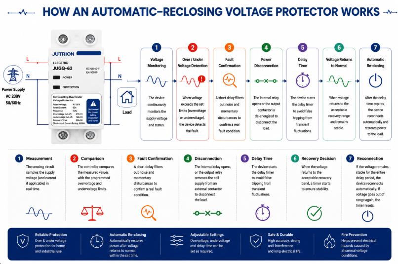
Automatic Re-closing Voltage Protector Working Principle Diagram- Measurement: the sensing circuit samples supply voltage and, on applicable models, current or additional phase conditions.
- Comparison: the controller compares measured values with the programmed overvoltage and undervoltage limits.
- Fault confirmation: filtering or a trip delay rejects insignificant noise and very short disturbances that should not disconnect the load.
- Disconnection: internal contacts open, or an output relay removes the coil supply from an external contactor.
- Continued monitoring: the source remains under observation while the downstream load is isolated.
- Recovery decision: when voltage returns to the acceptable recovery band, a timer starts.
- Reconnection: if the source stays stable for the full delay, the device reconnects automatically. If voltage becomes unacceptable again, the timer resets.
Microprocessor-based digital sampling makes adjustable thresholds, time delays, displays and status logic practical in a compact DIN-rail device. Filtering is important in electrically noisy installations because nuisance trips can be nearly as disruptive as the voltage event itself. The filter and confirmation time should reject insignificant deviations without masking a sustained condition that can damage the load.
Why the Trip Level, Recovery Level, and Delay Must Work Together
A protector does not make one voltage decision. It normally makes at least three related decisions: when the supply has become unacceptable, when it has recovered far enough to be considered acceptable again, and how long it must remain stable before the load is reconnected. These values form one control strategy and should be reviewed together.
If the trip and recovery levels are too close, a supply hovering near the boundary can cause repeated opening and closing. A separate recovery value creates hysteresis: after an undervoltage trip, for example, voltage must rise to a healthier level before reconnection becomes possible. The reconnection timer then confirms that the recovery is stable rather than momentary.
The correct timing follows the load. A resistive heater may accept a relatively quick return. A refrigeration compressor may need a longer pause before restart. A panel with several motors may need staged reconnection so their combined inrush does not pull the supply below the threshold again. This is why an adjustable delay is an engineering parameter, not merely a convenience feature.
For an adjustable model, record the approved trip, recovery, and delay values as one setting set. Changing only the high or low threshold can alter the intended hysteresis and restart behavior. For a factory-calibrated model, confirm that the preset control window matches the destination supply and the connected equipment before standardizing it across a project.
How to Select an Over and Under Voltage Protector
1. Confirm the System Voltage, Frequency and Phase Arrangement
Start with the actual distribution system, not a catalogue headline. Record nominal phase-to-neutral and phase-to-phase voltage, frequency, single- or three-phase arrangement, number of conductors, neutral use and acceptable supply tolerance. IEC 60038 provides standard voltage references, including common 230/400 V low-voltage systems, but the project specification and local supply rules determine the final requirements.
For three-phase loads, determine whether the device must also supervise phase loss, phase sequence, imbalance and phase-to-neutral displacement. For a panel containing many single-phase loads, neutral-related monitoring may be more important than it is for a balanced three-wire motor load.
2. Define the Load That Will Be Disconnected
List the connected load, maximum demand, continuous current, inrush current and load type. A 40 A resistive circuit, a 40 A motor feeder and a 40 A bank of switched-mode power supplies do not impose identical switching duty. Identify compressors, pumps, transformers, capacitive inputs and equipment with internal undervoltage or restart controls.
Do not select solely from the service breaker rating. The protector must be suitable for the current it carries and the switching duty it performs, while the upstream protective device must provide the required short-circuit protection. Terminal capacity, conductor size, ambient temperature and enclosure ventilation also matter.
3. Decide Between Direct Switching and an External Contactor
A compact protector can switch a suitably rated load directly when its contact rating, utilization duty and prospective fault coordination are appropriate. For a larger panel, a motor-heavy load, frequent operation or a current beyond the protector’s direct-switching capability, use a monitoring relay or protector to control a correctly selected contactor. This separates the measurement logic from the power switching duty.
When an external contactor is used, check coil voltage, contactor utilization category, auxiliary contacts, control-circuit protection and fail-safe behavior. Decide what happens after a power loss and whether automatic restart is permitted by the process risk assessment.
4. Set the Overvoltage and Undervoltage Limits
The trip window should be wide enough to tolerate normal supply variation and narrow enough to protect the connected equipment. Use the most restrictive credible requirement from the equipment manufacturer, project specification and local installation rules. A value seen in a generic example is not automatically suitable for motors, refrigeration, medical equipment, telecom power supplies or process controls.
| Setting | Purpose | Selection question |
|---|---|---|
| Overvoltage trip level | Defines the high-voltage disconnection point | What sustained input can the most sensitive connected equipment tolerate? |
| Undervoltage trip level | Defines the low-voltage disconnection point | At what voltage can motors, contactors or power supplies no longer operate safely? |
| Trip delay | Rejects brief deviations | Which short disturbances can the load ride through without harm? |
| Recovery level | Defines when voltage is acceptable again | Is sufficient hysteresis provided to avoid repeated switching? |
| Reconnection delay | Waits for stable supply and safe restart | Does the load need seconds or minutes before restart? |
5. Select Reconnection Delay for the Load
A short delay can restore lighting or non-critical resistive loads quickly. Refrigeration and air-conditioning compressors often require a longer delay to allow pressure equalization and avoid a hard restart. Multiple loads reconnecting simultaneously can create a new voltage dip, so large installations may require staged restarting rather than one common timer.
Automatic reconnection is convenient, but it is not appropriate everywhere. Machinery that could move unexpectedly may require manual reset, a safety controller or another supervised restart sequence. Voltage restoration must never bypass machine-safety requirements.
6. Check Poles, Neutral Arrangement and Isolation
Select the number of poles from the system earthing arrangement and installation requirements. Switching the neutral is not a universal rule. In some systems it is required; in others it may be prohibited or unnecessary. The choice must be coordinated with upstream bonding, source transfer arrangements and local codes. Never treat a two-pole or four-pole catalogue option as proof that it is correct for every network.
7. Verify Coordination and Installation Conditions
Confirm rated current, operational voltage, frequency, terminal capacity, mounting method, temperature range, enclosure protection and the required upstream protective device. Check short-circuit coordination rather than assuming a small modular device can interrupt any available fault current. Verify conductor torque and provide working space and ventilation according to the manufacturer’s instructions.
IEC 60364-4-44 addresses protection of low-voltage installations against voltage disturbances and electromagnetic disturbances. Apply the edition and national adoption required by the destination market; do not use an IEC reference as a substitute for a complete project design.
Standards and Export-Market Questions That Change the Specification
Standards references should define the engineering boundary, not decorate a product description. IEC 60364-4-44:2024 addresses protection of low-voltage installations against voltage disturbances and electromagnetic disturbances. It is an installation-level document: it helps designers consider the consequences of disturbances within an electrical installation, but it is not a model datasheet and does not by itself prove that a particular protector is suitable for a project.
IEC 60038 defines standard voltage values used as references for equipment and supply systems. Nominal voltage is the starting point for a protector setting, not the complete setting decision. Normal service variation, the connected equipment’s permissible input range, regional supply-quality requirements and the behavior of the recovery logic all affect the usable window.
Product Standard, Installation Code and Supply Quality
These three layers answer different questions. A product standard describes how a device is classified, constructed and tested. An installation code determines how equipment is selected and erected in a building or plant. A supply-quality document describes characteristics expected at the point of supply. A buyer should not substitute one layer for another. For example, knowing that a country uses a 230/400 V nominal system does not determine the required neutral switching, and an installation-code reference does not establish the short-circuit capability of an individual product.
The destination market may also use a national adoption of an IEC document with local modifications. North American projects use different system conventions, product listings and installation rules. The familiar functions—measure, compare, disconnect and delay reconnection—remain understandable, but product acceptance, conductor switching, enclosure marking and coordination have to be checked in the regional framework.
Certification Claims Must Match the Exact Model
Terms such as IEC, UL and CB should be supported by documentation that identifies the relevant standard, model or series, electrical ratings and issuing body. A general factory capability statement is not the same as a certificate covering every variant. Importers and panel builders should match the document reference to the ordered catalogue number and destination-market requirement.
The same discipline applies to rated current and protection claims. If a series includes several current or pole variants, evidence for one variant should not automatically be extended to all others. Where a protector includes overcurrent functionality, clarify its operating characteristic and its relationship to the upstream breaker. “Overcurrent” on a display does not automatically mean the device provides the short-circuit interruption performance expected from an MCB or MCCB.
A Compact Export Specification
Before comparing models, put the project conditions on one line: destination market; nominal voltage and frequency; phase and neutral arrangement; continuous current and load type; overvoltage and undervoltage limits; trip and reconnection timing; number of switched poles; direct switching or contactor control; upstream protection; mounting and environmental conditions; and required conformity documents. That line exposes mismatches quickly and prevents three products with the same front-panel current marking from being treated as equivalent.
For distributors serving several countries, adjustable models can reduce stock fragmentation, but only when setting control is managed. A setting range is useful if commissioning personnel know the approved values and unauthorized changes are prevented. For one stable market and a repeatable panel design, factory-calibrated thresholds may produce more consistent installation and simpler training. The export decision is therefore partly electrical and partly operational.
Choosing Between the Three JUTRION Series
JUTRION offers three over and under voltage protector series for different panel and procurement priorities. Product selection should still be confirmed against the required electrical ratings and project documentation.
| Selection point | JRGQ-63 | JQGQ-63 | JUGQ-63 |
|---|---|---|---|
| Series position | Flagship adjustable model | Compact digital model | Cost-effective preset model |
| Display and monitoring | Dual digital display with real-time voltage and current monitoring | Compact digital display with smart monitoring | Simplified interface for plug-and-play use |
| Voltage settings | Adjustable overvoltage and undervoltage parameters | Adjustable thresholds | Factory-calibrated thresholds |
| Additional function stated on the public page | Overcurrent protection and automatic reclosing | Automatic reclosing | Automatic reclosing |
| Installation format | 35 mm DIN-rail modular format | Space-saving DIN-rail format | Streamlined DIN-rail format |
| Best fit | Projects needing visible operating data and broad parameter control | High-density distribution boards where space matters | Standardized, high-volume applications requiring simple installation |
| Confirm from the ordered model datasheet | Rated voltage, current, poles, exact setting and delay ranges, terminals, temperature limits, dimensions, switching duty, upstream protection and model-specific conformity documents | ||
Choose JRGQ-63 when adjustment, current information and a more complete on-device interface are valuable. Choose JQGQ-63 when adjustable digital protection is needed but panel density is the main constraint. Choose JUGQ-63 when the required protection window matches the factory-calibrated configuration and consistency, simplicity and volume economics are more important than field adjustment.
A buyer should not compare only unit price. Normalize rated voltage, current, poles, adjustable range, trip and recovery logic, delay range, switching method, display, overcurrent function, terminals, certifications, packaging and customization. Two devices described as “63 A automatic voltage protectors” can offer materially different functions.
Apply the Selection Logic to Four Panel Scenarios
Commercial Distribution Board on an Unstable Grid
A small commercial facility experiences long evening brownouts and occasional high voltage during light-load periods. The panel supplies lighting, point-of-sale equipment, refrigeration and office electronics. A voltage protector can disconnect selected downstream circuits outside the approved window. Because refrigeration has a different restart requirement from lighting and office loads, the designer may divide the loads or use separate control so one common reconnection delay does not compromise either continuity or compressor protection.
OEM Panel for Pumps or HVAC Equipment
The load includes motors with high starting current and a control circuit sensitive to low voltage. Direct switching through a compact protector may not be the preferred architecture. The protector can monitor the source and command an AC contactor selected for the motor duty. The control design should prevent unsafe automatic restart and coordinate undervoltage behavior with the motor protection relay and process controller.
Three-Phase Panel with Many Single-Phase Loads
A 400/230 V panel distributes different single-phase circuits across the three phases. Unequal loading makes an open neutral hazardous. The monitoring strategy should observe all relevant phase-to-neutral voltages and disconnect the affected distribution section if values diverge beyond permitted limits. Maintenance procedures must still locate and repair the neutral fault.
High-Volume Standardized Consumer Unit
An OEM produces many panels for one market with a stable, predefined protection specification. Field adjustment is not needed and could create commissioning inconsistency. A factory-calibrated automatic-reclosing model such as JUGQ-63 may provide a simpler fit, provided its nominal voltage, current, thresholds, poles and certification match the project.
Install, Commission, and Diagnose the Protection System
Installation and Commissioning Checklist
- Confirm the source is isolated and follow the project’s lockout procedure.
- Verify nominal voltage, frequency, phase arrangement and conductor identification.
- Confirm whether the protector switches the load directly or controls a contactor.
- Check upstream short-circuit and overload protection.
- Match conductor size and terminal capacity; tighten to the specified torque.
- Program thresholds and delays from the approved setting schedule.
- Test overvoltage and undervoltage operation with suitable test equipment rather than by creating unsafe supply conditions.
- Verify the trip indication, contact state and reconnection timer.
- Confirm that motors and machinery restart safely.
- Record settings, model, serial or batch information and commissioning results.
After commissioning, investigate frequent trips instead of simply widening thresholds. Repeated operation may reveal a loose neutral, undersized feeder, overloaded transformer, generator-control issue or supply-quality problem. The protector is often the messenger, not the cause.
Common Selection and Installation Mistakes
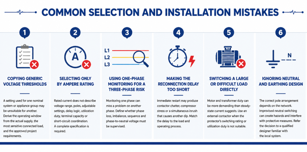
Common selection and installation mistakes of automatic re-closing voltage protector- Copying generic voltage thresholds: A setting used for one nominal system or appliance group may be unsuitable for another. Derive the operating window from the actual supply, the most sensitive connected load, and the approved project requirements.
- Selecting only by ampere rating: Rated current does not describe voltage range, poles, adjustable settings, delay logic, utilization duty, terminal capacity or short-circuit coordination. A complete specification is required.
- Using one-phase monitoring for a three-phase risk: Monitoring one phase can miss a problem on another phase. Define whether phase loss, imbalance, sequence and phase-to-neutral voltage must be supervised.
- Making the reconnection delay too short: Immediate restart may produce contactor chatter, compressor stress or a simultaneous inrush that causes another dip. Match the delay to the load and operating process.
- Switching a large or difficult load directly: Motor and transformer duty can be more demanding than steady-state current suggests. Use an external contactor when the protector’s switching rating or utilization duty is not suitable.
- Ignoring neutral and earthing design: The correct pole arrangement depends on the network. Improvised neutral switching can create hazards and interfere with protective measures. Refer the decision to a qualified designer familiar with the local system.
Maintenance and Troubleshooting in Service
A voltage protector normally requires little routine intervention, but it should still be included in the panel inspection plan. Check for discoloration, heat damage, loose terminals, dust accumulation, cracked housings and abnormal display values. Compare the displayed voltage with a calibrated instrument when readings appear doubtful. Thermal imaging under representative load can help reveal a poor terminal connection, although it does not replace torque checks performed under safe isolated conditions.
Keep a record of trip events where operational continuity matters. The time, displayed voltage, affected phase, connected load and recovery time can distinguish a supply-quality issue from a load-related voltage drop. Several trips at the same production time may indicate feeder demand. Random high and low readings across single-phase circuits may point toward a neutral problem. Trips only during generator operation may indicate AVR settings, frequency variation or poor generator/load matching.
| Observed symptom | Possible causes to investigate | Useful checks |
|---|---|---|
| Trips immediately after installation | Wrong nominal-voltage model, wiring error, threshold set too close to normal supply | Verify model, line/neutral connections, measured voltage and setting schedule |
| Repeated trip and reconnect cycle | Insufficient hysteresis, unstable supply, restart inrush causing another dip | Record voltage during restart; review recovery level and delay |
| Display is on but load remains off | Active fault, delay still counting, damaged contact, external contactor/control issue | Read status indication and test control circuit according to the manual |
| One phase shows abnormal voltage | Loose phase or neutral, phase imbalance, upstream connection fault | Isolate safely and inspect all conductors; measure every relevant phase |
| Terminal temperature is high | Loose termination, unsuitable conductor, overload, poor enclosure ventilation | Measure load current, inspect conductor preparation and verify specified torque |
Do not repeatedly reset or bypass a protector until the cause is known. Bypassing removes the protection at the moment the system may be demonstrating a genuine fault. If the device has switched a severe or repeated load, inspect its contacts and connected conductors according to the manufacturer’s service instructions. Replace a unit that shows heat damage, unreliable switching or readings outside its declared accuracy rather than attempting an unapproved repair.
Settings should also be controlled. For adjustable models, record the approved values during commissioning and restrict unauthorized changes. If equipment is added, the supply changes, or the panel is exported to a market with a different nominal voltage, review the entire setting schedule. A protector that was correctly configured for the original installation may be inappropriate after a system modification.
Frequently Asked Questions
Why does the protector wait before reconnecting the load?
The delay confirms that voltage has recovered and prevents rapid cycling. It can also provide restart time for compressors and reduce the chance that simultaneous inrush drives the supply low again.
Can it protect against a lost neutral?
It can reduce exposure if it monitors the affected phase-to-neutral voltages and disconnects when they leave the permitted range. It cannot repair the neutral fault, and the monitoring arrangement must cover all relevant phases.
Is an over/under voltage protector the same as a voltage stabilizer?
No. A protector disconnects the load. A stabilizer or AVR attempts to correct the output voltage while continuing to supply it. Choose according to whether shutdown or continuous regulated power is required.
How do I choose the ampere rating?
Determine the maximum current the device will carry, consider load duty and inrush, select a suitable rating with the required terminals and installation conditions, and coordinate it with upstream fault protection. Use an external contactor when direct switching is unsuitable.
What reconnection delay should I use?
Use the connected equipment manufacturer’s requirement and the process risk assessment. General lighting may accept a short delay; compressors and staged systems may need substantially longer or sequenced reconnection.
Why does the protector keep tripping?
Possible causes include genuine supply variation, a loose neutral, overloaded feeder, generator regulation problems, incorrect settings, wiring errors or a device/load mismatch. Measure and diagnose the system before widening the thresholds.
Choose the Protection Boundary Before the Product Variant
An over and under voltage protector is most effective when its operating window is defined precisely. Selection becomes a practical sequence: establish the nominal system and monitored conductors, understand the load, choose direct switching or contactor control, set coordinated trip and recovery values, choose a safe reconnection delay, verify poles and neutral design, and test the completed panel under controlled conditions.
For a model recommendation, send JUTRION the nominal voltage and frequency, phase and neutral arrangement, load current and type, required thresholds and delay, pole configuration, upstream protective device, installation conditions, certification market and order quantity. The JRGQ-63, JQGQ-63 and JUGQ-63 ranges can then be compared against the actual project instead of selected from current rating alone.
Technical References
