

275 V เทียบกับ 320 V เทียบกับ 385 V SPD: วิธีการเลือก Uc ที่ถูกต้อง
275 V, 320 V หรือ 385 V: คำตอบสั้น ๆ
สำหรับการติดตั้ง 230/400 V AC, SPD 275 V มักจะเป็นตัวเลือกแรกเมื่อโหมดการป้องกันของมันมักจะเห็นประมาณ 230 V แต่ไม่ใช่ตัวเลือกอัตโนมัติสำหรับทุกเครือข่าย ใช้ 320 V เมื่อการออกแบบที่ได้รับการอนุมัติจำเป็นต้องมีแรงดันไฟฟ้าต่อเนื่องหรือแรงดันไฟฟ้าชั่วคราวที่สูงขึ้น และใช้ 385 V เฉพาะเมื่อโหมดการป้องกันจริง การจัดการดิน และข้อมูลของผู้ผลิตยืนยันว่าค่าที่สูงกว่านั้นเหมาะสม อย่าเลือกจากแรงดันไฟฟ้าระบบที่ตั้งชื่อเพียงอย่างเดียว.
U ที่ถูกต้องc คือแรงดันไฟฟ้าสูงสุดที่ได้รับการอนุมัติซึ่งยังคงอยู่เหนือแรงดันไฟฟ้าสูงสุดที่ SPD สามารถประสบได้อย่างต่อเนื่องในโหมดที่เชื่อมต่อ มันต้องสามารถทนต่อสภาวะแรงดันไฟฟ้าชั่วคราวที่คาดหวังในจุดนั้นได้ หลังจากเลือก Uc, ตรวจสอบว่าแรงดันไฟฟ้าระดับการป้องกันที่ได้ Up ยังคงต่ำพอสำหรับอุปกรณ์ที่ได้รับการป้องกัน.
การตรวจสอบครั้งสุดท้ายนี้มีความสำคัญเพราะ Uc ไม่ใช่การจัดอันดับกระแสเกิน A 385 V cartridge ไม่ใช่เวอร์ชันที่แข็งแกร่งกว่าของ 275 V cartridge ในทุกด้าน มันอาจทนต่อแรงดันไฟฟ้าความถี่พลังงานที่สูงขึ้น แต่สามารถเริ่มจำกัดที่แรงดันไฟฟ้าที่สูงขึ้นและอาจมี U ที่ประกาศสูงกว่าp. ดังนั้นการเลือกที่ดีที่สุดจึงต้องมีความสมดุลระหว่างความเสถียรในการบริการกับระดับการป้องกัน.
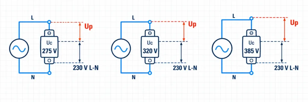
การเปรียบเทียบการจัดอันดับ Uc ของ SPD 275 V, 320 V และ 385 V บนวงจร 230 V ระหว่างสายกับกลางUc หมายถึงอะไรใน SPD AC
Uc คือแรงดันไฟฟ้าทำงานต่อเนื่องสูงสุดที่อาจถูกนำไปใช้ข้ามขั้ว SPD ภายใต้เงื่อนไขที่ระบุโดยผู้ผลิต สำหรับผลิตภัณฑ์ AC มันมักจะเป็นค่ารากที่สองที่ความถี่ที่ประกาศ ในระหว่างการทำงานปกติ SPD ต้องยังคงเสถียรที่แรงดันไฟฟ้านี้โดยไม่ทำตัวเหมือนว่าแต่ละยอดของไฟฟ้าหลักเป็นการกระชาก.
คำจำกัดความนี้อธิบายว่าทำไม Uc ต้องอ่านข้ามโหมดการป้องกันเฉพาะหนึ่งโหมด:
- L–N: เฟสกับกลาง;
- L–PE: เฟสกับดินป้องกัน;
- N–PE: กลางกับดินป้องกัน; หรือ
- L–L: เฟสกับเฟสในการจัดเรียงที่ออกแบบสำหรับโหมดนั้น.
เครือข่ายสามเฟสอาจถูกอธิบายว่าเป็น 230/400 V แต่แรงดันไฟฟ้าข้ามโมดูล SPD แต่ละตัวสามารถเป็น 230 V หรือ 400 V ขึ้นอยู่กับว่าโมดูลนั้นเชื่อมต่อที่ไหน ป้ายระบบและป้าย cartridge จึงไม่สามารถใช้แทนกันได้.
อย่าสับสน Uc กับตัวเลขอื่น ๆ ที่พิมพ์บน SPD:
| การทำเครื่องหมาย | สิ่งที่มันอธิบาย | สิ่งที่มันไม่พิสูจน์ |
|---|---|---|
| Uc | แรงดันไฟฟ้าสูงสุดที่อาจคงอยู่ตลอดในโหมดการป้องกันที่ประกาศ | ความสามารถในการปล่อยกระแสเกินหรือแรงดันไฟฟ้าที่ส่งไปยังโหลดในระหว่างการกระชาก |
| Up | ระดับการป้องกันแรงดันไฟฟ้าที่ประกาศภายใต้เงื่อนไขการทดสอบแรงกระตุ้นที่ระบุ | ความทนทานต่อแรงดันไฟฟ้าทำงานต่อเนื่อง |
| In | หน้าที่กระแสปล่อยตาม nominal โดยใช้รูปคลื่น 8/20 µs | ความสามารถในการทนต่อฟ้าผ่าโดยตรง |
| Iสูงสุด | กระแสปล่อยสูงสุดสำหรับ SPD ประเภท 2 ภายใต้การทดสอบ 8/20 µs ที่ระบุ | หน้าที่ซ้ำที่ค่านั้นสูงสุด |
| Iimp | หน้าที่กระแสกระตุ้นที่เกี่ยวข้องกับการทดสอบประเภท 1 และรูปคลื่น 10/350 µs | แทนที่ Uc หรือ Up |
| UT / ข้อมูล TOV | พฤติกรรมภายใต้แรงดันไฟฟ้าชั่วคราวที่กำหนดสำหรับระยะเวลาที่ระบุ | อนุญาตให้ทำงานต่อเนื่องที่แรงดันไฟฟ้านั้น |
สำหรับคำอธิบายที่กว้างขึ้นเกี่ยวกับประเภทของ SPD, การจัดอันดับกระแสการปล่อยและตำแหน่งการติดตั้ง, ใช้ คู่มืออุปกรณ์ป้องกันการกระชากของ JUTRION. บทความนี้จะมุ่งเน้นไปที่การตัดสินใจที่แคบกว่า: การเลือกในหมู่ค่า Uc 275 V, 320 V และ 385 V.
ทำไมการจัดอันดับทั้งสามจึงปรากฏในโครงการ 230/400 V
The three ratings exist because a low-voltage system does not present one perfectly fixed voltage under all operating and fault conditions. Supply tolerance, voltage regulation, harmonic distortion, neutral displacement, earth faults and the earthing arrangement can change the voltage applied to a protection mode. Product families also differ in their TOV behaviour and internal technology.
For a nominal 230 V phase-to-neutral supply, the simple ratio is:
275 / 230 = 1.20, 320 / 230 = 1.39, and 385 / 230 = 1.67.
These ratios are useful for seeing the increasing continuous-voltage margin, but they are not a complete selection formula. They do not describe the site’s maximum steady-state voltage, the protection mode, or how the SPD behaves during a TOV. Two SPDs with the same Uc can also have different UT, ค่า Up, backup-protection and disconnection data.
| Uc class | Typical reason it enters the shortlist | Main benefit | Main check before approval |
|---|---|---|---|
| 275 V AC | The protection mode normally sees approximately 230 V and the product’s TOV data suits the network | Tighter voltage margin often supports a relatively low protection level | Can it remain stable at the site’s highest continuous voltage and survive the specified TOV? |
| 320 V AC | The design needs additional operating-voltage margin, or the manufacturer assigns this class to the required network arrangement | More tolerance to sustained voltage elevation than a 275 V class | Is its Up still coordinated with the equipment impulse withstand voltage? |
| 385 V AC | The connected mode or approved TOV strategy requires substantially more voltage margin | Reduced risk of unwanted operation from elevated power-frequency voltage | Does the higher class leave a sufficiently low effective protection level at the load? |
This is a screening table, not a universal substitution chart. A 320 V device cannot automatically replace a 275 V device, and a 385 V device cannot be approved merely because it is less likely to react to an elevated mains voltage.
Start with the Voltage Across Each Protection Mode
Draw the SPD connection before choosing the cartridge. Mark the normal voltage across every mode and ask what voltage can appear there during the credible operating and fault states defined by the project.
Single-Phase 230 V, L–N Protection
An SPD connected from line to neutral normally sees the phase-to-neutral voltage. In an ordinary, correctly regulated 230 V system, 275 V is commonly shortlisted. The approval still depends on the permitted supply range, site measurements where relevant, TOV requirements and the exact datasheet.
If the site regularly operates near or above the upper boundary assumed by the design, selecting 275 V from the nominal label alone can cause accelerated ageing or unnecessary thermal disconnector operation. The engineering response is not automatically “fit 385 V.” First determine whether the elevated voltage is a valid operating condition, a supply-quality problem, a neutral fault or an application outside the original design.
Three-Phase 230/400 V, L–N or L–PE Protection
In a 230/400 V wye system, each phase is about 230 V to neutral and about 400 V to another phase. A module connected L–N is therefore not continuously exposed to 400 V during normal operation. A module connected in another mode may face a different requirement.
This distinction is why pole count does not select Uc. “Four-pole SPD for a 400 V panel” is incomplete. The specification must state the network configuration and protection circuit, such as 3+1 or 4+0, and identify the voltage across each module.
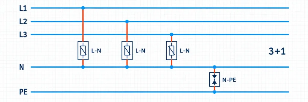
Three-phase 3+1 SPD arrangement with L1, L2 and L3 protected to neutral and a separate N-PE module.Earthing System and Circuit Arrangement Change the Answer
The same 230/400 V nominal supply can require a different SPD assembly depending on whether it is TN-C, TN-S, TT or IT. The important question is not only how many modules are installed, but which components are connected between which conductors.
TN Systems
TN-C and TN-S systems have different PEN or N/PE connection points, so use an assembly declared for the specific TN arrangement. A 275 V cartridge is common for a 230 V protection mode, but its TOV performance still has to pass; 320 V or 385 V variants are used only where the required continuous-voltage or TOV margin supports them.
TT Systems and 3+1 Circuits
A 3+1 arrangement commonly places voltage-limiting components from phase to neutral and a spark-gap-based component from neutral to PE. The phase cartridges are therefore selected for L–N duty; the N–PE component has different data. This arrangement can control TOV consequences in TT systems, but it must follow the applicable installation standard and manufacturer instructions.
IT Systems
In an IT system, healthy conductors can rise relative to earth after the first earth fault. Do not specify a 275 V L–PE cartridge solely because the loads are called 230 V. Use an assembly declared for the IT arrangement and verify conductor-to-earth voltage, protection modes and TOV behaviour.
The Real Trade-Off: Nuisance Ageing Versus Protection Level
Choosing Uc too low and choosing it too high create different problems.
If Uc Is Too Low
A metal-oxide varistor is voltage-dependent. Repeated or sustained operation too close to its continuous limit can increase leakage, temperature and ageing. A temporary overvoltage outside the declared capability can cause the internal thermal disconnector to operate, leaving the downstream circuit energized but no longer surge-protected. In a severe mismatch, the failure can be unsafe unless the product and backup protection clear it correctly.
A red indicator shortly after commissioning does not necessarily prove that the site experienced an exceptional lightning event. The investigation should include steady-state voltage, neutral integrity, wiring, TOV exposure, backup protection and whether the installed Uc and circuit match the network.
If Uc Is Too High
A higher-Uc varistor normally begins significant conduction at a higher voltage. Depending on the product design, this can raise Up. For example, one manufacturer’s otherwise comparable single-pole Type 2 family declares Up at no more than 1.5 kV for its 275 V and 320 V versions, but no more than 1.75 kV for its 385 V version. That is a product example, not a universal conversion rule, but it shows why the higher number is not automatically superior.
The relevant protection at the load is not just the catalogue Up. Connection-lead inductance adds voltage while surge current rises. Long conductors can erase the apparent advantage of a lower Up. Uc, ค่า Up, conductor length and equipment impulse withstand voltage must therefore be coordinated together.
Selection principle: choose the lowest Uc class that is approved for the maximum continuous voltage, protection mode, earthing arrangement and TOV duty. Then confirm that its Up and installed lead voltage remain below the protected equipment’s impulse withstand requirement with an adequate margin.
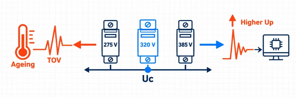
SPD Uc selection trade-off between low-voltage ageing and a higher downstream voltage protection level.Field Case: Why Moving Straight to 385 V Left the VFDs Exposed
An anonymized cold-chain packaging facility in Southeast Asia experienced repeated SPD disconnector operation on secondary 230/400 V distribution panels during the first three months after commissioning. The indicators on several installed 275 V Type 2 cartridges changed to red. The local contractor assumed that frequent lightning surges were exhausting the SPDs and replaced the cartridges with 385 V versions, treating the higher Uc as a heavier-duty rating.
Two months later, a grid-switching event was followed by dielectric failure in three variable frequency drives and two digital controller cards. The 385 V cartridges remained serviceable, forcing the investigation to separate the original nuisance disconnection from the later failure of protection coordination.
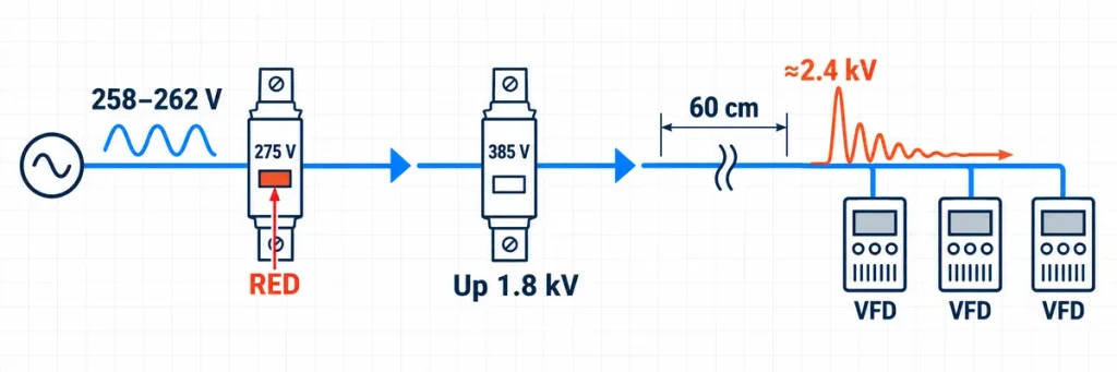
Field case showing a 385 V SPD, 60 cm connection path and approximately 2.4 kV reaching downstream VFDs.Why the 275 V Cartridges Were Disconnecting
Recorded phase-to-neutral voltage repeatedly reached 258–262 V AC RMS and contained notable fifth-harmonic distortion. The investigation attributed rising varistor leakage and temperature to prolonged power-frequency stress rather than repeated lightning impulses. This does not mean every 275 V SPD will fail at 262 V: the response also depends on TOV data, waveform, ambient temperature and ageing. Here, the site measurements and product data had not been reviewed together.
Why the 385 V Replacement Was Not an Equivalent Upgrade
The 385 V cartridges tolerated the elevated supply, but their declared Up was 1.8 kV versus no more than 1.35 kV for the original cartridges. The 60 cm connection path was estimated, for the assessed surge current and geometry, to add about 0.6 kV. The resulting 2.4 kV first-pass estimate did not exceed the drives’ stated 2.5 kV impulse withstand, but it left almost no margin for tolerance, waveform and installation effects.
Resolution: Use the Middle Voltage Class and Shorten the Current Path
The replacement used a JUTRION 320 V Type 2 configuration declared at Up ≤ 1.4 kV. Its Uc provided approximately 22% margin over the recorded 262 V RMS, subject to confirmation against the product documentation and site TOV assessment. Busbar comb connections and optimized V-wiring reduced the total path from about 60 cm to less than 25 cm; under the same estimation method, inductive addition fell below approximately 0.25 kV and the effective protection estimate stayed below about 1.65 kV.
No repeat nuisance disconnection or related controller damage was reported during the observation period. The correction combined sufficient continuous-voltage margin, a lower Up and a shorter discharge path instead of automatically selecting the highest Uc.
A Worked 230/400 V Panel Comparison
For an illustrative 230/400 V commercial board with separate N and PE conductors and a 3+1 SPD, review the candidates in this order:
- Identify the mode voltage. Each phase module is connected L–N, so it normally sees about 230 V, not 400 V.
- Establish the highest continuous supply voltage. Use the project’s supply tolerance and any verified site data. Do not treat an abnormal neutral condition as an ordinary continuous operating point.
- Define TOV duty. Review the earthing system, plausible neutral and earth faults, and the UT-versus-time data required by the installation design.
- Compare approved products. A 275 V version may provide adequate continuous and TOV performance. If it does not, the 320 V version may be evaluated. A 385 V version remains a candidate only if the higher margin is actually necessary.
- Recheck protection performance. Compare Up for each exact model, then include the effect of the connecting conductors and coordination with downstream protection.
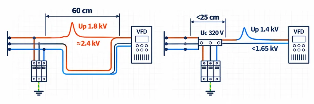
Comparison of a 60 cm SPD connection and optimized V-wiring under 25 cm for improved VFD protection.If 275 V passes the continuous-voltage and TOV checks, it normally remains the first candidate. Move to 320 V when additional margin is required and Up remains acceptable. Use 385 V only when the mode or TOV duty justifies it and the downstream protection calculation still passes.
Read Uc, ค่า UT and Up as One Set
An SPD datasheet should allow the designer to trace three different voltage questions:
- Uc: What voltage may remain continuously across this protection mode?
- UT or TOV characteristic: What happens at a stated power-frequency overvoltage and duration—does the SPD withstand it or fail safely?
- Up: To what declared level does the SPD limit a specified impulse at its terminals?
Do not infer one value from another. After voltage compatibility is established, separately verify Type 1, Type 2 or Type 1+2 duty; Iimp, In และ Iสูงสุด; prospective short-circuit current; disconnection; backup protection; and remote indication.
What to Put in an SPD Enquiry or Specification
“Need 4P 385 V SPD” is not enough information for a reliable product match. Send the electrical context that determines the cartridge duty:
- nominal system voltage and frequency;
- single-phase or three-phase conductor arrangement;
- earthing system: TN-C, TN-S, TT, IT or another defined arrangement;
- required protection circuit, such as 1+1, 3+1 or 4+0;
- SPD type and installation position;
- required Uc, TOV and Up performance;
- Iimp, In และ Iสูงสุด requirements;
- prospective short-circuit current and upstream protection;
- remote contact, replaceable module and certification requirements; and
- destination market, quantity and project documentation needs.
ประเภท JUTRION AC SPD range includes Type 2 and Type 1+2 options for low-voltage distribution systems. A final model should be matched to the actual network and connection diagram rather than selected from the Uc number in isolation.
Common Questions About 275 V, 320 V and 385 V SPDs
Can I use a 385 V SPD on a 230 V system?
Possibly, but it is not automatically the best choice. Confirm that the product is declared for the network and protection mode, then compare its Up with the protected equipment. The extra Uc margin is useful only if the design needs it and the resulting protection level remains acceptable.
Is a 275 V SPD always correct for a 230 V supply?
No. It is a common candidate for a mode that normally sees 230 V, but suitability depends on maximum continuous voltage, earthing system, TOV exposure, circuit arrangement and the exact datasheet.
Why would an SPD fail when no lightning strike was reported?
Possible causes include repeated switching surges, sustained overvoltage, a lost or unstable neutral, incorrect Uc, wrong protection circuit, ageing, loose connections or inadequate backup coordination. A failed indicator is a reason to investigate the system, not merely to fit a higher-voltage cartridge.
Does 320 V Uc mean a 320 V nominal system?
No. Uc is the maximum continuous voltage across the SPD protection mode, not necessarily the nominal line-to-line or line-to-neutral system designation. Read it with the connection diagram.
Are Uc and UCPV interchangeable?
No. UCPV is used for photovoltaic DC SPD applications and must be selected from the maximum PV string voltage under the project’s temperature conditions. For that task, use the separate DC SPD selection guide for solar PV.
The Practical Selection Rule
Do not choose 275 V, 320 V or 385 V from the front label of the distribution board. First establish the voltage across each SPD protection mode, then verify the highest continuous voltage, earthing arrangement and TOV duty. From the ratings that pass those checks, choose the option that still gives adequate Up coordination at the protected equipment.
In many ordinary 230 V protection modes, that process begins with 275 V. It moves to 320 V or 385 V only when the network conditions and manufacturer data support the change. Higher Uc is additional voltage margin—not a universal measure of better surge protection.
เอกสารอ้างอิงทางเทคนิค
