

ขนาดของ AC Contactor ที่ต้องการคือเท่าไหร่? การแปลงกำลังมอเตอร์จาก kW เป็น A, การจัดอันดับ AC-1 ถึง AC-4 และการเลือกขดลวด
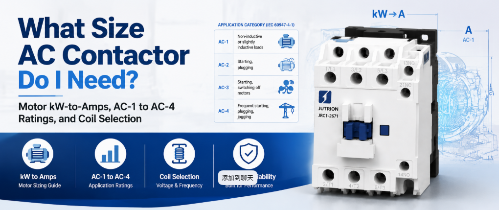
คำตอบด่วน: คอนแทคเตอร์ AC ทำหน้าที่อะไร?
คอนแทคเตอร์ AC คือสวิตช์ที่ควบคุมด้วยไฟฟ้า ใช้แม่เหล็กไฟฟ้าขับเคลื่อนขดลวดเพื่อเชื่อมต่อและตัดวงจรกำลังตามคำสั่ง ถูกออกแบบให้ทำงานได้หลายพันถึงล้านครั้งโดยไม่ให้ขั้วต่อเกิดการเชื่อมติดหรือสึกหรอ มันทำหน้าที่สวิตช์กระแสโหลดตามคำสั่ง แต่ไม่ใช่อุปกรณ์ป้องกันวงจร การเลือกขนาดที่ถูกต้องหมายถึงการเลือกตามเกรดที่เหมาะสมกับภาระงานจริง ไม่ใช่ตัวเลขสูงสุดที่ระบุบนฉลาก
คอนแทคเตอร์ที่ระบุ 20 A ไม่ใช่อุปกรณ์ 20 A สำหรับมอเตอร์เดียวกัน อุปกรณ์เดียวกันอาจได้รับการจัดอันดับ 20 A สำหรับฮีตเตอร์แบบต้านทาน และ 9 A สำหรับมอเตอร์แบบกรงกระรอก เนื่องจากกระแสเริ่มต้นและการตัดวงจรแบบเหนี่ยวนำของมอเตอร์ทำให้ขั้วต่อได้รับความเสียหายมากกว่าฮีตเตอร์ ความแตกต่างนี้เป็นสาเหตุหลักของความล้มเหลวของคอนแทคเตอร์ก่อนเวลาอันควรมากกว่าความผิดพลาดในการเลือกอื่นๆ
คู่มือนี้ครอบคลุมถึงภาระที่คอนแทคเตอร์ต้องรับ, วิธีการคำนวณ, หมวดหมู่การใช้งานที่เกี่ยวข้อง, รวมถึงการตรวจสอบขั้ว, ขดลวด, อุปกรณ์เสริม, อายุการใช้งาน และการประสานงานตามค่ากระแส
จับคู่ภาระงานสวิตช์กับอุปกรณ์ที่เหมาะสม
ก่อนเลือกขนาดใดๆ ให้ยืนยันว่าคอนแทคเตอร์เป็นอุปกรณ์ที่เหมาะสมสำหรับงานนั้น การออกแบบตู้ควบคุมมักล้มเหลวเพราะคาดหวังให้อุปกรณ์ชิ้นเดียวทำหน้าที่สองอย่างที่ไม่เกี่ยวข้องกัน
| อุปกรณ์ | งานหลัก | ความถี่ในการสวิตช์ | ตัดวงจรเมื่อเกิดความผิดปกติ (ฟอลต์) |
|---|---|---|---|
| คอนแทคเตอร์ AC | ปิดและตัดกระแสโหลดตามคำสั่ง | ออกแบบสำหรับการสวิตช์บ่อยครั้ง | ไม่ ต้องใช้รีเลย์โอเวอร์โหลดหรือเบรกเกอร์แยกต่างหาก |
| รีเลย์อเนกประสงค์ | สวิตช์กำลังต่ำและควบคุมสัญญาณ | ได้รับการจัดอันดับสำหรับงานเบา | No |
| MCB หรือ MCCB | ป้องกันกระแสเกินและลัดวงจร | ใช้งานเป็นครั้งคราว ไม่ใช่การสวิตช์เป็นประจำ | ใช่ |
| มอเตอร์สตาร์ทเตอร์ (Motor starter) | คอนแทคเตอร์และรีเลย์โอเวอร์โหลดในชุดเดียวกัน | เหมือนกับคอนแทคเตอร์ | ใช่ ผ่านรีเลย์โอเวอร์โหลด |
| ซอฟต์สตาร์ทเตอร์ หรือ VFD | การเพิ่มกระแสของมอเตอร์อย่างควบคุม | การควบคุมอย่างต่อเนื่องแทนการเปิด/ปิด | ขึ้นอยู่กับรุ่น |
ถ้าคำถามคือวิธีการสวิตช์โหลดเปิด-ปิดซ้ำ ๆ ตามคำสั่ง คำตอบคือคอนแทคเตอร์ แต่ถ้าคำถามคืออุปกรณ์ที่ป้องกันวงจรจากการโอเวอร์โหลด นั่นคืออุปกรณ์ที่แตกต่างกัน การถือว่าคอนแทคเตอร์ทำหน้าที่ทั้งสองอย่างเป็นหนึ่งในข้อผิดพลาดที่พบบ่อยที่สุดในการออกแบบตู้ควบคุม.
เหตุผลที่รีเลย์หรือเบรกเกอร์ไม่สามารถทดแทนได้
รีเลย์ทั่วไปสามารถปิดวงจรได้ แต่ไม่ได้ออกแบบมาให้ทำงานที่กระแสมอเตอร์หรือฮีตเตอร์ในระยะยาว คอนแทคเตอร์มีอายุการใช้งานทางกลนับล้านครั้ง ในขณะที่รีเลย์ทั่วไปมีอายุการใช้งานเพียงเศษเสี้ยวภายใต้ภาระไฟฟ้าจริง ความแตกต่างอยู่ที่วัสดุของคอนแทค แรงสปริง และการดับอาร์ค คอนแทคเตอร์ใช้รูปทรงคอนแทคและในกรอบขนาดใหญ่มีช่องดับอาร์คที่จำเป็นสำหรับตัดกระแสมอเตอร์เหนี่ยวนำซ้ำ ๆ โดยไม่ให้คอนแทคเกิดรอยบุ๋มหรือเชื่อมติด รีเลย์ที่ถูกใช้งานในหน้าที่นี้มักล้มเหลวโดยการเชื่อมติดภายใต้ภาระ ซึ่งเป็นโหมดล้มเหลวที่แย่กว่าการสึกหรอของคอนแทคเตอร์อย่างค่อยเป็นค่อยไป
เบรกเกอร์ถูกออกแบบมาเพื่อป้องกันวงจรและใช้งานเป็นครั้งคราว ไม่ได้ออกแบบมาให้สวิตช์เปิด-ปิดซ้ำ ๆ เป็นส่วนหนึ่งของตรรกะอัตโนมัติ การใช้เบรกเกอร์เป็นสวิตช์หน้าที่จะลดอายุการใช้งานป้องกันและไม่ใช่การใช้งานที่เหมาะสม คอนแทคเตอร์และอุปกรณ์ป้องกันทำหน้าที่ต่างกันและควรอยู่ในวงจรเดียวกัน.
การทำงานของคอนแทคเตอร์ AC
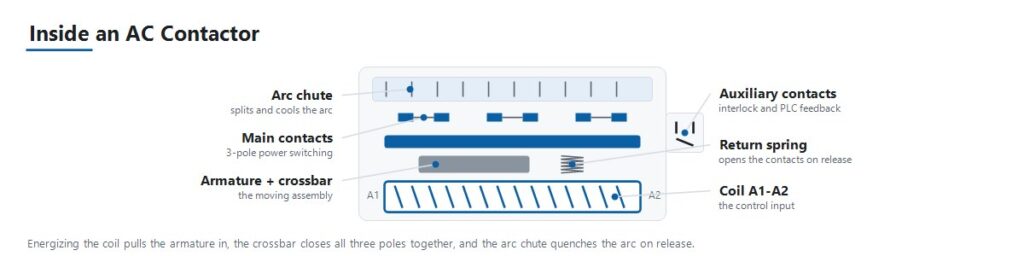
ลำดับการทำงานอธิบายโหมดล้มเหลวส่วนใหญ่ที่กล่าวถึงในคู่มือนี้
- สัญญาณควบคุมจ่ายพลังงานให้ขดลวด วงจรควบคุม เช่น เอาต์พุต PLC เทอร์โมสตัท หรือตรรกะปุ่มกด จะจ่ายแรงดันไฟฟ้าให้ขดลวดที่แรงดันขดลวดที่กำหนด
- แม่เหล็กไฟฟ้าดึงอาร์มาเจอร์เข้าหา ขดลวดที่มีกระแสไฟฟ้าสร้างสนามแม่เหล็กที่ดึงอาร์มาเจอร์เคลื่อนที่เข้าหาแกนแม่เหล็กคงที่
- คอนแทคหลักปิด การเคลื่อนที่ของอาร์มาเจอร์ปิดคอนแทคหลักผ่านแถบข้ามร่วม เชื่อมต่อโหลดกับแหล่งจ่ายไฟ
- คอนแทคเสริมเปลี่ยนสถานะ คอนแทคเสริมขนาดเล็กที่เชื่อมต่อกับอาร์มาเจอร์เดียวกันจะเปิดหรือปิดพร้อมกับคอนแทคหลัก เพื่อให้มีการล็อก การแสดงสถานะ และยืนยันกับ PLC ว่าคอนแทคเตอร์ปิดจริง
- แรงสปริงรักษาแรงกดคอนแทค แรงกดคอนแทคที่มั่นคงภายใต้การสั่นสะเทือนและภาระช่วยป้องกันการกระเด้งของคอนแทคและความร้อนจากความต้านทานที่ผิวคอนแทค
- การตัดพลังงานขดลวดเปิดวงจร เมื่อสัญญาณควบคุมลดลง สนามแม่เหล็กจะสลายและสปริงดึงอาร์มาเจอร์กลับ เปิดคอนแทคหลัก
- การดับอาร์คจัดการการตัดวงจร การเปิดวงจรภายใต้ภาระ โดยเฉพาะภาระมอเตอร์เหนี่ยวนำ จะเกิดอาร์คข้ามคอนแทคที่แยกออก ช่องดับอาร์คและรูปทรงคอนแทคช่วยดับอาร์คอย่างรวดเร็วพอที่จะป้องกันความเสียหายในทุก ๆ รอบ
หมวดหมู่การใช้งานกำหนดเรตติ้งกระแสจริง
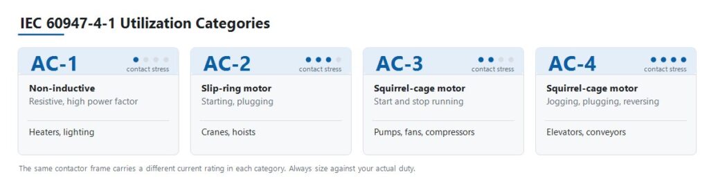
มาตรฐาน IEC 60947-4-1 กำหนดหมวดหมู่การใช้งานที่อธิบายความรุนแรงของโหลดต่อคอนแทค ไม่ใช่แค่จำนวนแอมแปร์ที่ดึง นี่คือขั้นตอนที่ทำให้เกิดข้อผิดพลาดในการเลือกส่วนใหญ่
| ประเภท | ประเภทโหลด | ลักษณะการสับสวิตช์ | การใช้งานทั่วไป |
|---|---|---|---|
| AC-1 | โหลดไม่เหนี่ยวนำหรือเหนี่ยวนำเล็กน้อย มีค่าปัจจัยกำลังสูง | ไม่มีการกระชากกระแสสำคัญ | ฮีตเตอร์แบบต้านทาน, ธนาคารความร้อน HVAC, แสงสว่างทั่วไป |
| AC-2 | มอเตอร์สลิปริง (โรเตอร์พันขดลวด) | การสตาร์ทและการหยุดภายใต้ภาระ | เครน, รอก |
| AC-3 | มอเตอร์แบบกรงกระรอก | การสตาร์ทและการตัดการทำงานของมอเตอร์ที่กำลังทำงาน | ปั๊ม, พัดลม, คอมเพรสเซอร์ |
| AC-4 | มอเตอร์แบบกรงกระรอก | การเดินช้า, การสต็อปแบบย้อนกลับ, การกลับทิศทางอย่างรวดเร็ว | ลิฟต์, สายพานลำเลียง, เครื่องมือเครื่องจักร |
ผลที่ตามมาคือคอนแทคเตอร์ตัวเดียวมีเรตติ้งกระแสไฟฟ้าหลายค่า JUTRION JRC1-D09 มีเรตติ้ง 20 A ในหมวด AC-1 และ 9 A ในหมวด AC-3 ทั้งสองค่าบรรยายอุปกรณ์ทางกายภาพเดียวกัน การเลือกขนาดปั๊มโดยใช้ค่า 20 A จะทำให้คอนแทคเตอร์ทำงานเกินกว่าค่าที่กำหนดสำหรับมอเตอร์มากกว่าสองเท่า และหน้าสัมผัสจะได้รับผลกระทบ
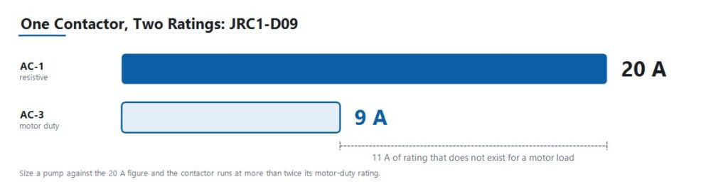
อ่านเรตติ้งที่เผยแพร่ทุกค่า พร้อมกับหมวดหมู่ที่เกี่ยวข้อง เฟรมไม่ใช่รุ่นเครนหรือรุ่นเดินช้า แต่เป็นเฟรมเดียวที่มีเรตติ้งหลายค่า และภาระงานจะเป็นตัวกำหนดว่าเรตติ้งใดใช้กับโครงการ
แปลงข้อมูลมอเตอร์เป็นกระแสไฟฟ้า (แอมป์)
ใช้กระแสไฟฟ้าระดับเต็มโหลดที่ได้รับการยืนยันโดยตรงเมื่อโครงการมีข้อมูลนี้แล้ว เมื่อข้อมูลเป็นกำลังมอเตอร์ ให้แปลงโดยใช้แรงดันและการจัดเฟสที่ถูกต้อง
มอเตอร์สามเฟส
I = P × 1,000 / (√3 × VLL × cos φ × η)
โหลดเฟสเดียว
I = P × 1,000 / (V × cos φ × η)
โดยที่, I คือกระแสไฟฟ้าสาย (line current) เป็นแอมแปร์, P คือกำลังขาออกของมอเตอร์เป็นกิโลวัตต์, VLL คือแรงดันสายต่อสายสามเฟส, V คือแรงดันเฟสเดียว, cos φ คือตัวประกอบกำลัง (power factor) และ η คือประสิทธิภาพ
กำลังไฟฟ้าสัมพัทธ์สำหรับมอเตอร์เหนี่ยวนำมาตรฐานมักอยู่ระหว่าง 0.80 ถึง 0.88 และประสิทธิภาพระหว่าง 0.85 ถึง 0.93 ขึ้นอยู่กับระดับประสิทธิภาพ ใช้ค่าจากแผ่นป้ายชื่อเมื่อมีอยู่ ช่วงค่าที่ระบุเป็นค่าประมาณสำหรับงานเบื้องต้นก่อนที่ข้อมูลมอเตอร์จะมาถึง
สำหรับโหลดเฟสเดียวที่เป็นตัวต้านทานล้วน เช่น ตัวทำความร้อน กำลังไฟฟ้าสัมพัทธ์และประสิทธิภาพจะเท่ากับหนึ่ง และสมการจะลดลงเป็น I = P × 1,000 / V.
ประเภท เครื่องคำนวณขนาดคอนแทคเตอร์ AC ของ JUTRION ทำการคำนวณเดียวกันและแสดงค่ากระแสไฟฟ้าขั้นต่ำสำหรับการทำงานในหมวด AC-3 เป็นจุดเริ่มต้นสำหรับการกำหนดสเปค ไม่ใช่ตัวแทนของแผ่นป้ายชื่อมอเตอร์หรือ ตารางเรตติ้งของผู้ผลิต
ใช้ตัวคูณประเภทโหลดและการลดค่าตามสภาพแวดล้อม
โหลดบางประเภทดึงกระแสไฟฟ้ามากกว่ากระแสคงที่ในช่วงเวลาที่สวิตช์เปิด การปฏิบัติในอุตสาหกรรมที่ยาวนานใช้ตัวคูณเพื่อชดเชยพฤติกรรมนี้ ข้อตกลงเหล่านี้ไม่ใช่ค่าที่กำหนดใน IEC 60947-4-1 ดังนั้นให้ใช้เป็นการประมาณครั้งแรกและยืนยันกับข้อมูลกระแสไฟฟ้าเริ่มต้นจริงสำหรับวงจรที่สำคัญหรือขนาดใหญ่
| ประเภทโหลด | ตัวคูณตามมาตรฐาน | เหตุผล |
|---|---|---|
| แบงค์ตัวเก็บประจุ | ประมาณ 1.5 × กระแสเรตติ้งของตัวเก็บประจุ | กระแสไฟฟ้าเริ่มต้นของตัวเก็บประจุเมื่อสวิตช์เปิดมีความรุนแรงและสั้นมาก |
| หม้อแปลงและชุดเชื่อม | ประมาณ 2 × กระแสพิกัด | กระแสเริ่มแม่เหล็กสามารถสูงกว่ากระแสคงที่หลายเท่า |
| โคมไฟชนิดปล่อยก๊าซและ HID | ประมาณ 1.1 ถึง 1.4 × กระแสพิกัด | พฤติกรรมกระแสเริ่มและการอุ่นเครื่องของบัลลาสต์ |
| การระบายความร้อนไม่ดีหรือกล่องบรรจุแน่น | 110 ถึง 120 เปอร์เซ็นต์ของกระแสพิกัดโหลด | อุณหภูมิภายในที่สูงขึ้นลดความสามารถในการจ่ายกระแส |
| มอเตอร์ที่ทำงานต่อเนื่อง, งานระยะยาว | กระแสพิกัดของคอนแทคเตอร์ลดลงประมาณ 30 เปอร์เซ็นต์ | การรับภาระความร้อนอย่างต่อเนื่องของขั้วติดต่อ |
อุณหภูมิแวดล้อมและสภาพกล่องบรรจุ
กระแสพิกัดของคอนแทคเตอร์ถือว่าอุณหภูมิแวดล้อมอ้างอิงตามที่ระบุในแผ่นข้อมูลสินค้า เมื่ออุณหภูมิสูงกว่านั้น ความสามารถในการจ่ายกระแสจะลดลง แต่ความชันของการลดค่าจะขึ้นอยู่กับผู้ผลิตและโครงสร้าง ใช้กราฟการลดค่าจากเอกสารผลิตภัณฑ์จริงแทนเปอร์เซ็นต์ทั่วไป.
มีสองเงื่อนไขที่ใช้ได้กับทุกผลิตภัณฑ์ ประการแรก ให้คำนวณจากอุณหภูมิภายในกล่องบรรจุ ไม่ใช่อุณหภูมิห้อง แผงควบคุมที่บรรจุแน่นในโรงงานที่ร้อนจะร้อนกว่าค่าอุณหภูมิแวดล้อมมาก ประการที่สอง คอนแทคเตอร์ที่ติดตั้งชิดกันโดยไม่มีช่องว่างจะทำให้ความร้อนสะสมซึ่งกันและกัน ดังนั้นควรปฏิบัติตามระยะห่างขั้นต่ำของผู้ผลิตหรือปรับลดค่ากระแสพิกัดเพิ่มเติม
ตัวอย่างการคำนวณ: มอเตอร์ปั๊ม 4 kW ที่ 400 V
มอเตอร์ปั๊มแรงเหวี่ยงสามเฟสในแผง OEM สำหรับบำบัดน้ำ งานสตาร์ทและหยุดปกติ ประมาณ 20 ครั้งต่อชั่วโมง อุณหภูมิแวดล้อมแผงประมาณ 35 °C
ขั้นตอนที่ 1 กำหนดหมวดหมู่การใช้งาน มอเตอร์เหนี่ยวนำแบบกรงกระรอกที่สตาร์ทและหยุดตามปกติเป็นหมวดหมู่ AC-3 ไม่ใช่ AC-1 แม้ว่าจะเป็นโหลดปั๊มธรรมดาก็ตาม
ขั้นตอนที่ 2 คำนวณกระแสเต็มโหลด ค่าบนแผ่นชื่อคือ 4 kW, 400 V, cos φ = 0.85, η = 0.90
I = 4 × 1,000 / (1.732 × 400 × 0.85 × 0.90)
คำนวณตัวส่วน: 1.732 × 400 = 692.8, จากนั้น × 0.85 = 588.9, จากนั้น × 0.90 = 530.0
I = 4,000 / 530.0 ≈ 7.6 A
ขั้นตอนที่ 3 เลือกตามเรตติ้ง AC-3 ต้องการคอนแทคเตอร์ที่มีเรตติ้ง AC-3 ครอบคลุม 7.6 A พร้อมเฮดรูม คอนแทคเตอร์ JRC1-D09 มีเรตติ้ง 9 A ที่ AC-3 ให้เฮดรูมประมาณ 18 เปอร์เซ็นต์เหนือกระแสเต็มโหลดที่คำนวณ โปรดสังเกตสิ่งที่ไม่ได้ทำ: JRC1-D09 เดียวกันมีเรตติ้ง AC-1 ที่ 20 A และการเลือกคอนแทคเตอร์โดยใช้ตัวเลขนี้เป็นข้อผิดพลาดที่พบบ่อยที่สุด
ขั้นตอนที่ 4 ตรวจสอบอุณหภูมิแวดล้อมและงาน ที่อุณหภูมิแวดล้อมแผง 35 °C พร้อมเฮดรูม 18 เปอร์เซ็นต์ ให้ตรวจสอบค่ากับกราฟการลดค่าของผลิตภัณฑ์ก่อนตัดสินใจ เฮดรูมนี้เหมาะสมในแผงที่มีการระบายอากาศดีและแคบในแผงที่บรรจุแน่น ที่ 20 ครั้งสตาร์ทต่อชั่วโมง ให้ยืนยันว่าจำนวนการทำงานต่อชั่วโมงและอายุไฟฟ้า AC-3 เกินกว่าที่คาดไว้ตลอดอายุการใช้งานของแผง
ขั้นตอนที่ 5 ระบุแรงดันขดลวด หม้อแปลงควบคุมในแผงมีแรงดันทุติยภูมิ 220 V AC ดังนั้นขดลวดจึงระบุที่ 220 V ไม่ใช่ 400 V แม้ว่ามอเตอร์จะทำงานที่ 400 V
ขั้นตอนที่ 6 เพิ่มการป้องกัน จับคู่คอนแทคเตอร์กับรีเลย์โอเวอร์โหลดที่มีขนาดเหมาะสมตั้งค่าตามกระแสเต็มโหลดของมอเตอร์ และยืนยันการประสานงานประเภท 1 หรือ 2 กับเบรกเกอร์หรือฟิวส์ด้านบน การสตาร์ทปกติภายใน 10 วินาทีแนะนำให้ใช้คลาสทริป Class 10 ที่นี่ เครื่องคำนวณการตั้งค่ารีเลย์โอเวอร์โหลด แปลงกระแสบนแผ่นชื่อ, ปัจจัยบริการ และระยะเวลาสตาร์ทเป็นการตั้งค่าเบื้องต้นและคลาสทริป
ผลลัพธ์: JRC1-D09 แบบสามขั้ว พร้อมขดลวด 220 V AC และรีเลย์โอเวอร์โหลด การเลือกนี้มาจากโหลด ไม่ใช่จากแคตตาล็อก
ขั้นตอนเดียวกันนี้ใช้ได้กับกำลังไฟสูงกว่า มอเตอร์ 18.5 kW ที่ 400 V จะมีกระแสเต็มโหลดประมาณ 35 A และต้องการคอนแทคเตอร์ที่มีเรตติ้ง AC-3 สูงกว่าค่านี้
ใช้กระบวนการเลือก AC Contactor เจ็ดขั้นตอนนี้
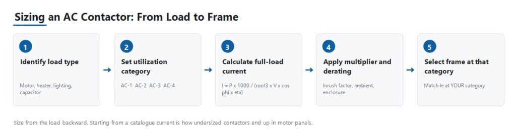
ขั้นตอนที่ 1: ระบุประเภทโหลดและหมวดหมู่การใช้งาน
กำหนดว่าโหลดเป็นแบบต้านทาน มอเตอร์แบบกรงกระรอกมาตรฐาน มอเตอร์โรเตอร์พันขดที่เริ่มต้นภายใต้โหลด หรือมอเตอร์ที่มีการวิ่งจ็อกกิ้งและย้อนกลับ ทุกอย่างที่ตามมาขึ้นอยู่กับคำตอบนี้ เพราะจะกำหนดว่ากระแสไฟฟ้าระบุของคอนแทคเตอร์ตัวใดที่ใช้จริง
ขั้นตอนที่ 2: คำนวณกระแสการทำงานและยืนยันแรงดันไฟฟ้า
ใช้สูตรด้านบนเพื่อหากระแสเต็มโหลด นำตัวคูณประเภทโหลดที่เกี่ยวข้องมาใช้ จากนั้นยืนยันว่ากระแสการทำงานที่ระบุ Ie ในหมวดหมู่การใช้งานของคุณครอบคลุมพร้อมเผื่อไว้ ให้ตรงกับแรงดันไฟฟ้าการทำงานที่ระบุ Ue กับแรงดันไฟฟ้าระบบสาย
ขั้นตอนที่ 3: เลือกแรงดันขดลวด
แรงดันขดลวดเป็นข้อกำหนดแยกต่างหากจากแรงดันโหลด วงจรมอเตอร์ 380 V อาจถูกสวิตช์โดยขดลวด 24 V DC หรือ 220 V AC ขึ้นอยู่กับสถาปัตยกรรมการควบคุม ยืนยันว่าวงจรควบคุมจ่ายอะไรจริง ๆ ไม่ว่าจะเป็นเอาต์พุต PLC หม้อแปลงควบคุมทุติยภูมิ หรือแหล่งจ่ายไฟ DC ก่อนสั่งซื้อ
ขั้นตอนที่ 4: เลือกจำนวนขั้วและการจัดวาง
สามขั้วเป็นมาตรฐานสำหรับโหลดมอเตอร์สามเฟส สี่ขั้วใช้เมื่อจำเป็นต้องสวิตช์นิวตรัลหรือวงจรอิสระเพิ่มเติม ยืนยันการจัดวางตามการออกแบบระบบกราวด์ เนื่องจากบางระบบต้องสวิตช์นิวตรัลและบางระบบไม่จำเป็นหรือห้าม
ขั้นตอนที่ 5: ระบุขั้วเสริม
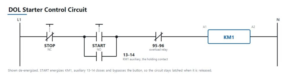
กำหนดจำนวนขั้วเสริมแบบปกติเปิดและปกติปิดที่ต้องการสำหรับการล็อกวงจร การส่งสถานะ PLC และหลอดไฟแสดงสถานะ และว่าขั้วเสริมเหล่านั้นเป็นแบบบูรณาการหรือเพิ่มเป็นบล็อกเสริมแยก ในสตาร์ทเตอร์แบบตรง (DOL) ขั้วเสริมที่เดินสายขนานกับปุ่มสตาร์ทจะล็อกวงจรควบคุมเพื่อให้คอนแทคเตอร์ยังคงทำงานหลังจากผู้ปฏิบัติงานปล่อยปุ่ม ขั้วเสริมมีราคาถูกเมื่อระบุในขั้นตอนออกแบบและยุ่งยากเมื่อติดตั้งภายหลัง
ขั้นตอนที่ 6: ตรวจสอบอายุการใช้งานไฟฟ้าตามรอบการใช้งานจริง
สำหรับแอปพลิเคชันที่มีการสลับบ่อย เช่น การวิ่งจ็อกกิ้ง การย้อนกลับ หรือซีเควนซ์อัตโนมัติความถี่สูง ให้ตรวจสอบจำนวนการทำงานที่ระบุต่อชั่วโมงและอายุการใช้งานไฟฟ้าในหมวดหมู่การใช้งานของคุณ อายุการใช้งานทางกลที่วัดโดยไม่มีโหลดมักสูงกว่าและไม่เกี่ยวข้องมาก
ขั้นตอนที่ 7: ประสานงานกับการป้องกันด้านต้นทาง
จับคู่ contactor กับรีเลย์โอเวอร์โหลดที่มีขนาดเหมาะสมสำหรับโหลดมอเตอร์ จากนั้นประสานงานกับเบรกเกอร์หรือฟิวส์ด้านต้นทางที่มีขนาดสำหรับการป้องกันลัดวงจร ในตู้จ่ายไฟขนาดใหญ่ อุปกรณ์ต้นทางนั้นมักเป็น เบรกเกอร์อากาศการเลือก contactor เป็นส่วนหนึ่งของโซ่ที่เชื่อมจากกระแสโหลด ไปยังเรตติ้งเบรกเกอร์ ไปยังกระแสลัดวงจรที่คาดการณ์ และหน้าที่การตัดวงจรของอุปกรณ์ การเลือก contactor ให้ถูกต้องแต่ไม่ตรวจสอบโซ่ทั้งหมดจะทำให้ปัญหาเลื่อนไปที่อื่น
มาตรฐาน IEC 60947-4-1 และเรตติ้ง NEMA ไม่ใช่ป้ายกำกับที่ใช้แทนกันได้
AC contactor ที่จำหน่ายทั่วโลกโดยทั่วไปผลิตตาม IEC 60947-4-1 ซึ่งกำหนดหมวดหมู่การใช้งานและโครงสร้างเรตติ้งที่ใช้ในคู่มือนี้ ฉบับที่ห้าปัจจุบันเผยแพร่ในปี 2023 และแทนที่ฉบับปี 2018 ควรตรวจสอบว่าข้อกำหนดโครงการอ้างอิงฉบับใด เพราะไม่เหมือนกันทั้งหมด
ตลาดอเมริกาเหนือมักอ้างอิงเรตติ้ง contactor ตาม NEMA ICS 2 แทนหรือควบคู่กับหมวดหมู่การใช้งาน IEC ทั้งสองระบบจำแนก contactor แตกต่างกัน เนื่องจาก NEMA ใช้ขนาดคลาสแทน AC-1 ถึง AC-4 ข้อกำหนดที่เขียนสำหรับตลาดหนึ่งไม่สามารถแปลโดยอัตโนมัติไปยังอีกตลาดหนึ่ง เมื่อจัดหาโครงการอเมริกาเหนือ ให้ยืนยันกรอบข้อกำหนดที่ผู้ซื้อระบุจริงก่อนเสนอราคา
พิจารณามาตรฐานผลิตภัณฑ์ รหัสการติดตั้ง และข้อกำหนดเฉพาะตลาดเป็นคำถามแยกสามข้อ การยืนยันข้อใดข้อหนึ่งไม่ตอบคำถามอื่น
การประสานงานประเภท 1 และประเภท 2
การประสานงานลัดวงจรภายใต้ IEC 60947-4-1 กำหนดความเสียหายที่เกิดกับ contactor และสตาร์ทเตอร์ ประเภท 1 อนุญาตให้เกิดความเสียหายกับอุปกรณ์หลังลัดวงจรได้ ตราบใดที่ความเสียหายจำกัดและไม่ก่อให้เกิดอันตราย และอุปกรณ์อาจต้องซ่อมหรือเปลี่ยนใหม่ ประเภท 2 กำหนดให้อุปกรณ์ยังคงเหมาะสมสำหรับใช้งานต่อไป โดยอนุญาตให้เกิดการเชื่อมติดของขั้วเพียงเล็กน้อยเท่านั้น ผลลัพธ์ทางการค้าและวิศวกรรมแตกต่างกัน ยืนยันข้อกำหนดโครงการก่อนเลือกชุดอุปกรณ์
การเลือกเรตติ้ง JUTRION JRC1
JUTRION ผลิต AC contactor ซีรีส์ JRC1 บนสายการผลิตของตนเองที่เวินโจว เจ้อเจียง ผลิตตาม IEC 60947-4-1 ตัวเลือกแรงดันขดลวดมีตั้งแต่ 24 V, 48 V, 110 V, 220 V และ 380 ถึง 415 V ที่ 50 หรือ 60 Hz ทุกหน่วยผ่านการทดสอบการทำงานทางกล ประสิทธิภาพขดลวด และการสวิตช์ไฟฟ้าก่อนจัดส่ง
ต่อไปนี้เป็นจุดเรตติ้งที่เผยแพร่ในสี่หมวดหมู่การใช้งาน อ่านตารางตามหมวดหมู่แทนตามรุ่น เนื่องจากเฟรมเดียวกันอาจปรากฏในมากกว่าหนึ่งหมวดหมู่ด้วยเรตติ้งต่างกัน
| ประเภท | จุดเรตติ้ง | หน้าที่ที่แสดงถึง |
|---|---|---|
| AC-1 | JRC1-D09, 20 A | ฮีตเตอร์แบบต้านทาน, ธนาคารความร้อน HVAC, แสงสว่างทั่วไป |
| AC-2 | JRC1-D25, 25 A | มอเตอร์โรเตอร์พันขดลวด (Wound-rotor motors) ที่สตาร์ทภายใต้ภาระ, เครนและรอก |
| AC-3 | JRC1-D09, 9 A | มอเตอร์กรงกระรอก, การสตาร์ทและหยุดปกติ, ปั๊มและพัดลม |
| AC-4 | JRC1-D18, 7.7 A | การเคลื่อนที่แบบจ็อกกิ้ง, การเสียบปลั๊ก, การกลับทิศทางอย่างรวดเร็ว, ลิฟต์และสายพานลำเลียง |
JRC1-D09 ปรากฏสองครั้ง คือ 20 A ภายใต้ AC-1 และ 9 A ภายใต้ AC-3 เนื่องจากเป็นเรตติ้งสองแบบของคอนแทคเตอร์ตัวเดียวกันภายใต้หน้าที่ที่แตกต่างกัน สำหรับวงจรมอเตอร์เหนี่ยวนำมาตรฐาน ซึ่งครอบคลุมการใช้งานส่วนใหญ่ของปั๊ม, พัดลม และคอมเพรสเซอร์ ให้เลือกขนาดตามเรตติ้ง AC-3 ตามตัวอย่างที่แสดง สำหรับงานจ็อกกิ้งหรือการกลับทิศทาง ให้เลือกขนาดตาม AC-4 แทน ซึ่งเฟรมเดียวกันจะรับกระแสได้ต่ำกว่ามาก
เรตติ้งเฟรมที่สูงกว่าจุดที่เผยแพร่เหล่านี้มีให้เลือก การเลือกโมเดลสุดท้ายควรขึ้นอยู่กับเรตติ้งเฉพาะรุ่นและเงื่อนไขโครงการ ไม่ใช่แค่ตัวเลขกระแสเท่านั้น
ใช้ตรรกะการเลือกกับสถานการณ์แผงควบคุมห้าแบบ
แผงมอเตอร์มาตรฐานสำหรับปั๊ม, พัดลม และคอมเพรสเซอร์
OEM ที่ผลิตแผงควบคุมสำหรับ HVAC หรืออุปกรณ์บำบัดน้ำ กำหนดคอนแทคเตอร์สำหรับงานสตาร์ทและหยุดมอเตอร์แบบตรงไปตรงมา ซึ่งเป็นหมวดหมู่ AC-3 ให้เลือกขนาดเรตติ้ง AC-3 ตามกระแสโหลดเต็มที่ที่คำนวณได้ จับคู่กับรีเลย์โอเวอร์โหลดที่มีขนาดเหมาะสม และเลือกแรงดันขดลวดให้ตรงกับเอาต์พุตหม้อแปลงควบคุมของแผง
แผงเครนหรือรอกที่ใช้มอเตอร์โรเตอร์พันขดลวด
OEM เครนต้องการคอนแทคเตอร์ที่รองรับงานสตาร์ทแรงบิดสูงและการเสียบปลั๊กบนมอเตอร์โรเตอร์พันขดลวด ซึ่งเป็นหมวดหมู่ AC-2 ภาระเหล่านี้ทำให้เกิดความเสียหายต่อคอนแทคมากกว่างาน AC-3 ปกติ เนื่องจากการสตาร์ทซ้ำภายใต้ภาระและการกลับทิศทาง การเลือกขนาดเล็กเกินไปที่นี่จะแสดงออกเป็นการสึกหรอของคอนแทคก่อนเวลาแทนที่จะล้มเหลวทันที ซึ่งทำให้วินิจฉัยผิดพลาดว่าเป็นปัญหาคุณภาพได้ง่าย
การควบคุมลิฟต์หรือสายพานลำเลียงที่มีการจ็อกกิ้งและกลับทิศทาง
ผู้ผลิตเครื่องจักรต้องการคอนแทคเตอร์สำหรับงานที่มีการกลับทิศทางบ่อยและการเคลื่อนที่แบบจังหวะ ซึ่งเป็นหมวดหมู่ AC-4 ซึ่งเป็นงานที่ต้องการมากที่สุดในสี่หมวดหมู่ ชีวิตไฟฟ้าที่อัตราการทำงานจริงต่อชั่วโมงมีความสำคัญมากกว่าสถานการณ์อื่นๆ การเลือกขนาดเล็กเกินไปในหมวดหมู่นี้เป็นวิธีที่เร็วที่สุดในการลดอายุการใช้งานที่ระบุของคอนแทคเตอร์
การสวิตช์แบงค์ตัวเก็บประจุเพื่อปรับปรุงกำลังไฟฟ้า
สถานที่ที่เพิ่มตัวเก็บประจุปรับปรุงกำลังไฟฟ้าต้องการคอนแทคเตอร์ที่เลือกขนาดตามกระแสพุ่งของตัวเก็บประจุ ซึ่งโดยทั่วไปประมาณ 1.5 เท่าของกระแสเรตติ้งตัวเก็บประจุ และมักระบุให้มีตัวต้านทานพรีชาร์จหรือเป็นคอนแทคเตอร์เฉพาะสำหรับสวิตช์ตัวเก็บประจุ การเลือกขนาดตาม AC-1 มาตรฐานไม่เพียงพอ เนื่องจากกระแสพุ่งของตัวเก็บประจุเป็นงานสวิตช์ที่แตกต่างจากงานต้านทานแบบอ่อน
แผงทำความร้อนแบบต้านทานหรือแสงสว่าง
ผู้ผลิตแผงที่สวิตช์แบงค์ทำความร้อน HVAC หรือโหลดแสงสว่างขนาดใหญ่ทำงานในหมวดหมู่ AC-1 ซึ่งเป็นงานที่ต้องการน้อยที่สุด เนื่องจากไม่มีการพุ่งกระแสหรือแรงเหนี่ยวนำที่สำคัญที่ต้องจัดการ การคายประจุและแสง HID เป็นข้อยกเว้นและต้องใช้ตัวคูณ 1.1 ถึง 1.4 สำหรับกระแสพุ่งของบัลลาสต์ นี่คือกรณีที่ผู้ซื้อบางครั้งเลือกชิ้นส่วนเรตติ้ง AC-3 ซึ่งเกินความจำเป็น แต่ไม่เป็นอันตราย เพียงแต่เพิ่มต้นทุนโดยไม่จำเป็น
หลีกเลี่ยงข้อผิดพลาดเก้าประการที่ทำให้คอนแทคเตอร์เสียก่อนเวลา
| ข้อผิดพลาด | ผลลัพธ์ | การป้องกัน |
|---|---|---|
| เลือกขนาดตามเรตติ้ง AC-1 สำหรับโหลดมอเตอร์ | คอนแทคเตอร์มีขนาดเล็กเกินไปสำหรับงานจริง คอนแทคติดหรือสึกหรอก่อนเวลา | เลือกขนาดตามเรตติ้งสำหรับหมวดหมู่การใช้งานจริงเสมอ |
| ละเลยรีเลย์โอเวอร์โหลด | มอเตอร์และคอนแทคเตอร์เผชิญกับกระแสเกินอย่างต่อเนื่อง | จับคู่วงจรมอเตอร์ทุกวงกับรีเลย์โอเวอร์โหลดที่มีขนาดเหมาะสม |
| ไม่สนใจความถี่การสวิตช์เทียบกับอายุการใช้งานไฟฟ้า | คอนแทคเตอร์ที่มีขนาดกระแสถูกต้องยังล้มเหลวก่อนเวลาในงานที่มีรอบการทำงานสูง | ตรวจสอบจำนวนครั้งที่ทำงานต่อชั่วโมงและอายุการใช้งานไฟฟ้าที่หมวดหมู่ของคุณ |
| แรงดันขดลวดไม่ตรงกัน | คอนแทคเตอร์ไม่ดึงเข้าหรือขดลวดไหม้ | ยืนยันกับแรงดันวงจรควบคุมจริง ไม่ใช่แรงดันโหลด |
| ไม่มีการตรวจสอบการประสานงานด้านต้นทาง | ความผิดพลาดลัดวงจรทำลายคอนแทคเตอร์โดยไม่จำเป็น | ตรวจสอบการประสานงานประเภท 1 หรือประเภท 2 ก่อนสรุปแบบ |
| การสลับทิศทางคอนแทคเตอร์โดยไม่มีการล็อกกลไก | คอนแทคเตอร์ทั้งสองตัวสามารถปิดพร้อมกัน ทำให้เกิดลัดวงจรเฟสต่อเฟส | ระบุการล็อกกลไกและไฟฟ้าทั้งคู่ในคู่สลับทิศทาง |
| ละเลยอุณหภูมิแวดล้อมและการลดค่ากำลังของตู้ | อายุการใช้งานสั้นลงแม้ว่าสเปคอื่น ๆ จะถูกต้อง | ลดค่ากำลังโดยใช้กราฟผลิตภัณฑ์และอุณหภูมิตู้ |
| ลืมตัวคูณประเภทโหลด | กระแสไฟกระชากของตัวเก็บประจุ หม้อแปลง หรือแสงสว่างทำให้หน้าสัมผัสเสื่อมสภาพตามเวลา | ใช้ตัวคูณตามปกติสำหรับประเภทโหลด |
| ระบุหน้าสัมผัสเสริมช้าเกินไป | ต้องแก้ไขแผงวงจรอย่างมีค่าใช้จ่ายหรือบล็อกเสริมที่ไม่สะดวก | กำหนดความต้องการล็อกกลไกและฟีดแบ็กในขั้นตอนออกแบบ |
ติดตั้ง ทดสอบ และวินิจฉัยคอนแทคเตอร์
ข้อผิดพลาดของคอนแทคเตอร์ส่วนใหญ่ที่รายงานว่าเป็นข้อบกพร่องของผลิตภัณฑ์เป็นอาการของปัญหาการกำหนดขนาด การประสานงาน หรือแหล่งจ่ายควบคุม ตารางด้านล่างแสดงอาการทั่วไปกับการตรวจสอบที่ช่วยระบุสาเหตุ
| อาการ | สาเหตุที่เป็นไปได้ | การตรวจสอบที่มีประโยชน์ |
|---|---|---|
| เสียงคลิกหรือฮัมดัง | แรงดันขดลวดต่ำหรือไม่เสถียร ขดลวดบังแม่เหล็กสึกหรอ แกนแม่เหล็กสกปรกหรือหลวม | วัดแรงดันขดลวดขณะมีโหลด ตรวจสอบผิวแกนแม่เหล็ก ยืนยันความเสถียรของแหล่งจ่ายควบคุม |
| หน้าสัมผัสติดกัน | ขนาดเล็กกว่าประเภทที่แท้จริง เหตุการณ์ลัดวงจรโดยไม่มีการประสานงานที่เหมาะสม ความถี่การสวิตช์สูงเกินไป | ตรวจสอบขนาดตามประเภท ทบทวนประวัติความผิดพลาดด้านต้นทาง เปรียบเทียบจำนวนครั้งการทำงานต่อชั่วโมงกับอายุการใช้งานไฟฟ้าที่กำหนด |
| ไม่ทำงานแม้มีสัญญาณควบคุม | ขดลวดเปิดวงจร แรงดันขดลวดผิดพลาด การติดขัดทางกล ฟิวส์ควบคุมขาด | วัดความต้านทานและแรงดันขดลวดที่ขั้ว ตรวจสอบฟิวส์ควบคุม ตรวจสอบสิ่งกีดขวาง |
| หน้าสัมผัสเป็นหลุมหรือไหม้ | การสึกหรอตามอายุการใช้งานปกติ ขนาดเล็กกว่าประเภทงาน การระงับประกายไฟไม่ดีที่ความถี่สวิตช์สูง | เปรียบเทียบสภาพกับอายุการใช้งานไฟฟ้าที่กำหนด ตรวจสอบขนาดประเภทอีกครั้ง ตรวจสอบช่องระบายประกายไฟ |
| ฟีดแบ็กเสริมไม่ตรงกับสถานะหน้าสัมผัสหลัก | บล็อกเสริมสึกหรอหรือไม่ตรงตำแหน่ง การสึกหรอของกลไกลิงก์ | ทดสอบความต่อเนื่องของเสริมแยกต่างหาก ตรวจสอบลิงก์กับชุดหน้าสัมผัสหลัก |
| ขั้วต่อร้อนเกินไป | การต่อสายหลวม ตัวนำไฟฟ้าขนาดเล็กเกินไป แรงบิดไม่ถูกต้องขณะติดตั้ง | ตรวจสอบแรงบิดที่ขั้วต่อเทียบกับข้อกำหนด ตรวจสอบขนาดตัวนำไฟฟ้า ใช้ภาพความร้อนขณะมีโหลด |
| ขดลวดไหม้ซ้ำ ๆ | แรงดันเกินอย่างต่อเนื่องในวงจรควบคุม อุณหภูมิแวดล้อมสูงเกินไป การติดขัดทางกลทำให้ไม่สามารถดึงเต็มที่ได้ | วัดแรงดันควบคุมในทุกสภาวะการทำงาน ตรวจสอบการติดขัด ตรวจสอบอุณหภูมิแวดล้อม |
ความล้มเหลวซ้ำ ๆ ในแอปพลิเคชันเดียวกันมักบ่งชี้ถึงการเลือกขนาด การประสานงาน หรือวงจรงานที่ไม่ตรงกัน มากกว่าชุดชิ้นส่วนที่มีข้อบกพร่อง วิเคราะห์สาเหตุก่อนสั่งซื้อหมายเลขชิ้นส่วนเดิมซ้ำ
ปกป้องขดลวดและอุปกรณ์ที่ขับเคลื่อน
การตัดพลังงานให้กับขดลวดเหนี่ยวนำทำให้เกิดแรงดันทรานเซียนต์ เมื่อเอาต์พุตทรานซิสเตอร์ของ PLC รีเลย์อินเทอร์โพสซิ่งขนาดเล็ก หรือตัวควบคุมอิเล็กทรอนิกส์สวิตช์ขดลวดนั้นโดยตรง ทรานเซียนต์จะเดินทางย้อนกลับเข้าไปในอุปกรณ์นั้น นี่เป็นสาเหตุที่พบบ่อยของความล้มเหลวของเอาต์พุต PLC และหน้าสัมผัสสึกกร่อนบนรีเลย์อินเทอร์โพสซิ่ง และสามารถออกแบบป้องกันได้โดยตรง ใช้ RC สนับเบอร์คร่อมขดลวด AC และใช้ฟลายแบ็กไดโอดหรือวาริสเตอร์กับขดลวด DC โปรดสังเกตข้อแลกเปลี่ยน: ฟลายแบ็กไดโอดแบบธรรมดาทำให้เวลาปลดปล่อยยาวขึ้นอย่างเห็นได้ชัด ซึ่งมีความสำคัญเมื่อคอนแทกเตอร์เป็นส่วนหนึ่งของฟังก์ชันหยุดที่เกี่ยวข้องกับความปลอดภัยซึ่งมีเวลาตอบสนองที่กำหนดไว้.
ยืนยันพิกัดความทนแรงดันใช้งานของขดลวด แทนที่จะสมมติว่าค่าพิกัดระบุนั้นถูกต้อง สายควบคุมที่ยาวหรือหม้อแปลงควบคุมขนาดเล็กเกินไปอาจทำให้แรงดันจริงที่ขดลวดต่ำกว่าช่วงที่ขดลวดจะดูดเข้าและค้างไว้ได้ และอาการจะปรากฏเป็นการสั่นกระพือมากกว่าจะเป็นความผิดปกติของสายไฟที่ชัดเจน.
ระบุพารามิเตอร์เหล่านี้เมื่อขอใบเสนอราคา
การสอบถามเกี่ยวกับคอนแทกเตอร์ที่มีข้อมูลต่อไปนี้สามารถตอบกลับด้วยรุ่นเฉพาะได้ในการตอบครั้งแรก การสอบถามที่ให้เพียงค่าแอมแปร์มักต้องมีการสอบถามเพิ่มเติมหลายรอบ เนื่องจากค่ากระแสเพียงอย่างเดียวไม่สามารถระบุลักษณะงานที่ใช้ได้.
- การใช้งานหรืออุปกรณ์ที่ถูกควบคุม
- ประเภทโหลด: มอเตอร์ ฮีตเตอร์ ไฟแสงสว่าง คาปาซิเตอร์ หรือหม้อแปลง
- ประเภทการใช้งาน หากทราบแล้ว
- กำลังพิกัดมอเตอร์เป็นกิโลวัตต์ หรือโหลดเป็นกิโลวัตต์
- แรงดันระบบและความถี่
- กระแสโหลดเต็มพิกัดที่คำนวณได้
- ลักษณะงาน: จำนวนสตาร์ตต่อชั่วโมง และการใช้งานมีการกลับทางหรือจ็อกหรือไม่
- แรงดันขดลวดที่ต้องการ และเป็น AC หรือ DC
- จำนวนขั้ว สามขั้วหรือสี่ขั้ว
- หน้าสัมผัสช่วยที่ต้องการ ปกติเปิดและปกติปิด
- อุปกรณ์ป้องกันด้านต้นทาง เบรกเกอร์หรือฟิวส์
- อุณหภูมิแวดล้อมภายในตู้
- วิธีการติดตั้ง ราง DIN หรือสกรู
- ปริมาณสั่งซื้อและตลาดปลายทาง
- ข้อกำหนด OEM หรือ ODM ใดๆ
คำถามที่พบบ่อย
ความแตกต่างระหว่างคอนแทกเตอร์ AC กับมอเตอร์สตาร์ตเตอร์คืออะไร?
มอเตอร์สตาร์ตเตอร์คือคอนแทกเตอร์ที่รวมกับโอเวอร์โหลดรีเลย์ในชุดประกอบเดียว บรรจุเฉพาะสำหรับวงจรมอเตอร์ คอนแทกเตอร์แบบเดี่ยวให้ฟังก์ชันการสวิตช์เท่านั้น และการป้องกันโอเวอร์โหลดจะเพิ่มแยกต่างหาก.
คอนแทกเตอร์ตัวเดียวใช้กับโหลด AC-1 และ AC-3 ได้หรือไม่?
คอนแทกเตอร์ตัวเดียวกันมักมีพิกัดสำหรับหลายประเภท แต่มีพิกัดกระแสต่างกันในแต่ละประเภท เลือกขนาดตามพิกัดที่ตรงกับประเภทการใช้งานของโหลดจริง ไม่ใช่ตัวเลขสูงสุดบนฉลาก.
คำนวณกระแสสำหรับการเลือกขนาดคอนแทกเตอร์อย่างไร?
สำหรับมอเตอร์สามเฟส ใช้ I = P × 1,000 / (√3 × VLL × cos φ × η) โดยที่ P คือกำลังพิกัดเป็นกิโลวัตต์ VLL คือแรงดันระหว่างเฟส cos φ คือตัวประกอบกำลัง และ η คือประสิทธิภาพ จากนั้นใช้ตัวคูณตามประเภทโหลดและยืนยันผลลัพธ์กับพิกัดของคอนแทกเตอร์ที่ประเภทการใช้งานของคุณ.
คอนแทกเตอร์ขนาดใหญ่กว่าจะปลอดภัยกว่าเสมอหรือไม่?
ไม่ การเลือกขนาดใหญ่เกินทำให้สิ้นเปลืองต้นทุนและพื้นที่ตู้ และในโหลดบางประเภท หน้าสัมผัสของคอนแทกเตอร์ขนาดใหญ่เกินไปมีกระแสไหลผ่านน้อยเกินไปจนไม่สามารถรักษาความสะอาดได้ เลือกขนาดโดยมีส่วนเผื่อที่สมเหตุสมผลเหนือกระแสโหลดเต็มพิกัดที่คำนวณได้ในประเภทที่ถูกต้อง แทนที่จะข้ามขนาดเฟรมไปสองระดับ.
ควรเลือกแรงดันขดลวดเท่าใด?
เลือกให้ตรงกับสิ่งที่วงจรควบคุมจ่ายจริง ไม่ว่าจะเป็นเอาต์พุต PLC ขดลวดทุติยภูมิของหม้อแปลงควบคุม หรือแหล่งจ่าย DC ของตู้ ไม่ใช่แรงดันด้านโหลดที่คอนแทกเตอร์สวิตช์.
ทำไมคอนแทกเตอร์ของฉันจึงมีเสียงฮัมหรือสั่นกระพือ?
สาเหตุที่พบบ่อยคือแรงดันคอยล์ต่ำ ไม่เสถียร หรือไม่ถูกต้อง หรือหน้าขั้วแม่เหล็กสึกหรอหรือสกปรกบนชุดคอยล์ AC วัดแรงดันคอยล์ภายใต้สภาวะโหลดจริงและตรวจสอบหน้าขั้วแม่เหล็กก่อนสรุปว่าอุปกรณ์เสีย.
ฉันยังจำเป็นต้องใช้โอเวอร์โหลดรีเลย์หรือไม่หากใช้คอนแทคเตอร์อยู่แล้ว?
จำเป็น สำหรับวงจรมอเตอร์ คอนแทคเตอร์ตัดต่อตามคำสั่งแต่ไม่ตัดวงจรเมื่อมีกระแสเกินต่อเนื่อง ซึ่งเป็นหน้าที่ของโอเวอร์โหลดรีเลย์ อุปกรณ์ทั้งสองทำงานร่วมกันและไม่สามารถใช้แทนกันได้.
คอนแทคเตอร์รองรับรอบการสวิตชิ่งได้กี่ครั้ง?
ขึ้นอยู่กับขนาดเฟรมและที่สำคัญกว่านั้นคือประเภทการใช้งานและระดับกระแสที่ทำงาน อายุการใช้งานเชิงกลที่วัดโดยไม่มีโหลดมักสูงกว่าอายุการใช้งานทางไฟฟ้าภายใต้โหลดมาก และอายุการใช้งานทางไฟฟ้าจะลดลงอีกเมื่อความถี่ในการสวิตชิ่งสูงขึ้น ตรวจสอบอายุการใช้งานทางไฟฟ้าที่กำหนดที่รอบการทำงานจริง.
สามารถต่อคอนแทคเตอร์สองตัวแบบขนานเพื่อแบ่งกระแสได้หรือไม่?
โดยทั่วไปไม่แนะนำสำหรับการสวิตชิ่งโหลดหลัก หน้าสัมผัสไม่เคยปิดพร้อมกันพอดี ดังนั้นอุปกรณ์ตัวหนึ่งจะรับกระแสเมคกิ้งเต็มจำนวน ใช้คอนแทคเตอร์ตัวเดียวที่มีขนาดถูกต้องแทน.
ความแตกต่างระหว่างการประสานงานแบบ Type 1 และ Type 2 คืออะไร?
ตามมาตรฐาน IEC 60947-4-1 Type 1 อนุญาตให้คอนแทคเตอร์และสตาร์ทเตอร์เสียหายได้หลังจากเกิดความผิดพร่องลัดวงจร โดยความเสียหายต้องถูกจำกัดและไม่ก่อให้เกิดอันตราย Type 2 กำหนดให้อุปกรณ์ยังคงเหมาะสำหรับการใช้งานต่อไป โดยอนุญาตให้มีการเชื่อมติดของหน้าสัมผัสเพียงเล็กน้อยเท่านั้น ตรวจสอบว่าข้อกำหนดของโครงการต้องการแบบใด.
ฉันจำเป็นต้องลดพิกัดคอนแทคเตอร์สำหรับอุณหภูมิแวดล้อมสูงหรือไม่?
จำเป็น กระแสพิกัดอ้างอิงจากอุณหภูมิแวดล้อมตามเอกสารข้อมูล เมื่ออุณหภูมิสูงกว่านั้น ความสามารถในการรับกระแสจะลดลง ใช้กราฟลดพิกัดของผู้ผลิตและอ้างอิงจากอุณหภูมิภายในตู้แทนอุณหภูมิห้อง.
ฉันจะทดสอบคอนแทคเตอร์ AC ด้วยมัลติมิเตอร์ได้อย่างไร?
เมื่อวงจรถูกแยกและล็อกไว้ วัดความต้านทานคอยล์ระหว่าง A1 และ A2 วงจรเปิดหรือค่าที่อ่านได้ใกล้ศูนย์บ่งชี้ว่าคอยล์เสีย จากนั้นตรวจสอบความต่อเนื่องของขั้วหลักแต่ละขั้ว ซึ่งควรอ่านค่าเปิดเมื่อไม่จ่ายไฟและปิดเมื่อกดคอนแทคเตอร์ด้วยมือ เปรียบเทียบทั้งสามขั้ว เนื่องจากขั้วหนึ่งที่อ่านค่าแตกต่างอย่างเห็นได้ชัดบ่งชี้ถึงความเสียหายของหน้าสัมผัสที่ขั้วนั้น.
เลือกขนาดจากโหลด ไม่ใช่จากแคตตาล็อก
การเลือกคอนแทคเตอร์ที่เชื่อถือได้มาจากสิ่งที่การใช้งานต้องการและทำงานไปข้างหน้าสู่หมายเลขรุ่น การเริ่มจากขนาดเฟรมที่มีอยู่และหวังว่ารอบการทำงานจะพอดีคือวิธีที่คอนแทคเตอร์ขนาดเล็กเกินไปไปอยู่ในตู้มอเตอร์.
ลำดับการปฏิบัติตรงไปตรงมา: กำหนดโหลดและประเภทการใช้งาน คำนวณกระแสโหลดเต็มพิกัด ใช้ตัวคูณประเภทโหลดและการลดพิกัดจากอุณหภูมิแวดล้อม จากนั้นตรวจสอบกระแสการทำงานพิกัดของคอนแทคเตอร์ที่ประเภทนั้น หลังจากตัวเลขแอมแปร์ถูกกำหนดแล้วเท่านั้น การตรวจสอบขั้ว คอยล์ หน้าสัมผัสเสริม อายุการใช้งานทางไฟฟ้า และการประสานงานการลัดวงจรจึงจะทำให้ข้อกำหนดสมบูรณ์.
เมื่อข้อมูลเหล่านั้นได้รับการยืนยันแล้ว เปรียบเทียบกับรูปแบบที่มีอยู่ใน กลุ่มผลิตภัณฑ์คอนแทคเตอร์ AC JUTRION. การเลือกโมเดลขั้นสุดท้ายควรเป็นไปตามพิกัดเฉพาะของโมเดลและเงื่อนไขของโครงการ ไม่ใช่ตัวเลขปัจจุบันเพียงอย่างเดียว.
เอกสารอ้างอิงทางเทคนิค
