

Trong môi trường kỹ thuật thực tế, mất điện không bao giờ chỉ là “vài phút tối om.” Đối với các trung tâm dữ liệu hay bệnh viện, chỉ vài giây gián đoạn nguồn điện cũng có thể đồng nghĩa với thảm họa. Trên các dây chuyền sản xuất công nghiệp, một sự sụt áp bất ngờ có thể khiến cả mẻ nguyên liệu bị loại bỏ và dẫn đến quá trình khởi động lại thiết bị kéo dài. Ngay cả trong các tòa nhà thương mại cao cấp, sự cố của hệ thống phòng cháy và an ninh cũng là một rủi ro không thể chấp nhận.
Thiết bị chuyển nguồn tự động (ATS) chính là “tuyến phòng thủ cuối cùng” trong mạch nguồn cấp điện sống còn này. Là trung tâm cốt lõi của hệ thống nguồn kép, khi nguồn điện lưới chính gặp tình trạng thấp áp, mất điện hoặc thậm chí mất pha, ATS phải đưa ra quyết định chính xác trong thời gian rất ngắn, chuyển an toàn các tải quan trọng sang nguồn dự phòng và chỉ chuyển trở lại một cách êm ái sau khi nguồn điện lưới đã hoàn toàn ổn định trở lại.
Nhiều dự án mắc một sai lầm chết người trong quá trình mua sắm: họ cho rằng ATS chỉ là một “công tắc lớn” thông thường và chỉ cần chọn đúng dòng định mức là đủ. Trên thực tế, nó là “bộ điều khiển giao thông” giữa hai nguồn điện. Từ độ trễ tạo điện áp của máy phát, đến chiến lược chuyển mạch trung tính (lựa chọn cực), đến phối hợp bảo vệ ngắn mạch với các bộ ngắt mạch phía trước và phía sau, bất kỳ quyết định sai lầm nào ở một trong những chi tiết này đều có thể khiến toàn bộ hệ thống hỏng hóc vào thời điểm then chốt.
Nếu bạn vẫn đang ở giai đoạn đánh giá thiết bị của dự án, chúng tôi khuyên bạn trước tiên nên xem qua [Mục sản phẩm cốt lõi về Thiết bị chuyển nguồn tự động (ATS)],để bạn có thể nhanh chóng xác định kiến trúc cơ bản phù hợp nhất với hệ thống của mình.
Trong các dự án quốc tế, việc lựa chọn ATS không nên chỉ dựa vào catalog sản phẩm. Cần phải đánh giá theo các tiêu chuẩn và quy phạm hiện hành đứng sau sản phẩm, bao gồm IEC 60947-6-1 cho thiết bị đóng cắt chuyển nguồn dùng để đảm bảo tính liên tục của nguồn cấp, NFPA 70 (NEC) cho thiết kế và lắp đặt điện an toàn trong các dự án tại Hoa Kỳ, và NFPA 110 cho hệ thống nguồn khẩn cấp và dự phòng trong các tòa nhà và cơ sở.
Thiết bị chuyển nguồn tự động (ATS) là gì?
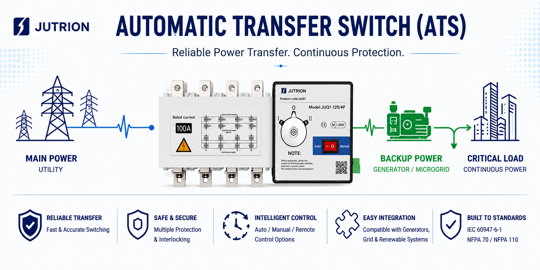
Thiết bị chuyển nguồn tự động (ATS) là một thiết bị đóng cắt quan trọng được sử dụng trong các hệ thống cấp nguồn kép. Nó thường được lắp đặt giữa nguồn điện chính và nguồn điện dự phòng, cho phép tải được chuyển từ nguồn này sang nguồn khác khi cần thiết. Các tổ hợp nguồn phổ biến bao gồm điện lưới - máy phát, điện lưới - điện lưới, và điện lưới - bộ lưu trữ năng lượng hoặc đầu ra biến tần.
Không giống như bộ ngắt mạch thông thường, mục đích chính của ATS không phải là trực tiếp cắt dòng sự cố. Chức năng cốt lõi của nó là đảm bảo việc chuyển đổi tin cậy, có kiểm soát và được khóa liên động đúng cách giữa hai nguồn điện khả dụng. Vì lý do này, thiết kế ATS thường tập trung vào cơ cấu chuyển mạch, logic điều khiển, giám sát nguồn, khóa liên động cơ khí và điện, và tính liên tục của toàn bộ hệ thống cấp nguồn.
Từ góc độ kỹ thuật, ATS về bản chất là một thiết bị dùng để duy trì tính liên tục của nguồn cấp. IEC cũng cung cấp một khung tiêu chuẩn rõ ràng cho thiết bị đóng cắt chuyển nguồn và thiết bị đóng cắt chuyển nguồn tự động. Do đó, trong các dự án xuất khẩu, dự án EPC và các ứng dụng kỹ thuật xuyên biên giới, các tiêu chuẩn hiện hành, tài liệu thử nghiệm và giới hạn vận hành của ATS đều là những yếu tố cần cân nhắc then chốt.
Cách ATS hoạt động giữa nguồn điện chính và nguồn dự phòng
Quy trình làm việc của ATS giữa nguồn điện chính và nguồn điện dự phòng chủ yếu bao gồm giám sát thời gian thực, phán đoán sự cố, chuyển mạch đáng tin cậy và tự động chuyển nguồn trở lại. Toàn bộ quá trình hoàn toàn tự động và được trang bị khóa liên động an toàn, có thể chia cụ thể thành bốn giai đoạn:
Giai đoạn vận hành bình thường (Nguồn điện chính đang hoạt động)
Theo mặc định, ATS cấp nguồn cho tải từ nguồn điện chính (điện lưới), trong khi bộ điều khiển liên tục giám sát các thông số chính của nguồn chính 24/7, chẳng hạn như điện áp, tần số và tình trạng pha. Nguồn điện dự phòng vẫn ở chế độ chờ nóng, và các thiết bị chuyển mạch chính và dự phòng được khóa liên động cơ khí và/hoặc điện để ngăn chặn nghiêm ngặt việc đóng đồng thời, nhờ đó tránh được hiện tượng ngắn mạch giữa hai nguồn điện.
Giai đoạn sự cố nguồn chính (Kích hoạt chuyển nguồn)
Khi nguồn điện chính gặp sự cố mất điện, điện áp thấp, quá áp, mất pha hoặc tần số bất thường, ATS trước tiên sẽ áp dụng độ trễ xác nhận sự cố có thể cấu hình (thường là 0,5–5 giây) để lọc bỏ các dao động tức thời. Khi sự cố được xác nhận là có thật, trình tự sau sẽ diễn ra:
- Bộ điều khiển gửi lệnh để dẫn động cơ cấu mở công tắc nguồn chính;
- Sau khi công tắc nguồn chính được mở hoàn toàn, công tắc nguồn dự phòng sau đó được đóng lại. Trong một số ứng dụng, hệ thống trước tiên phải đợi cho đến khi nguồn điện dự phòng ổn định, chẳng hạn như khi máy phát điện đã khởi động và đạt đến điện áp và tần số định mức;
- Tải sau đó được chuyển sang nguồn điện dự phòng. Toàn bộ quá trình thường được hoàn thành trong vòng mili giây, do đó các tải quan trọng có thể gặp rất ít hoặc gần như không có gián đoạn đáng kể.
Giai đoạn cấp nguồn dự phòng
ATS tiếp tục giám sát trạng thái phục hồi của nguồn điện chính trong khi duy trì cấp nguồn ổn định từ nguồn dự phòng cho tải. Một số mẫu còn bao gồm giám sát sự cố nguồn dự phòng, giúp giảm rủi ro cả hai nguồn điện cùng hỏng.
Giai đoạn phục hồi nguồn chính (Tự động chuyển nguồn trở lại)
Khi điện áp và tần số của nguồn điện chính trở về phạm vi chấp nhận được và duy trì ổn định trong một khoảng thời gian nhất định (có thể cấu hình, ví dụ 1–30 phút), ATS thực hiện tự động chuyển nguồn trở lại từ nguồn dự phòng sang nguồn chính:
- Trước tiên nó mở công tắc nguồn dự phòng, sau đó đóng công tắc nguồn chính;
- Tải được chuyển trở lại nguồn điện chính, trong khi nguồn dự phòng trở về
Thiết kế an toàn chính: ATS sử dụng cơ cấu khóa liên động cơ khí và/hoặc điện để đảm bảo rằng công tắc nguồn chính và công tắc nguồn dự phòng không bao giờ có thể đóng đồng thời trong bất kỳ trường hợp nào, ngăn chặn hoàn toàn các rủi ro nghiêm trọng như dòng điện tuần hoàn và ngắn mạch. Đây cũng là điểm khác biệt cơ bản nhất giữa ATS và cách bố trí công tắc kép thông thường.
Các thành phần chính của Bộ chuyển nguồn tự động (ATS)
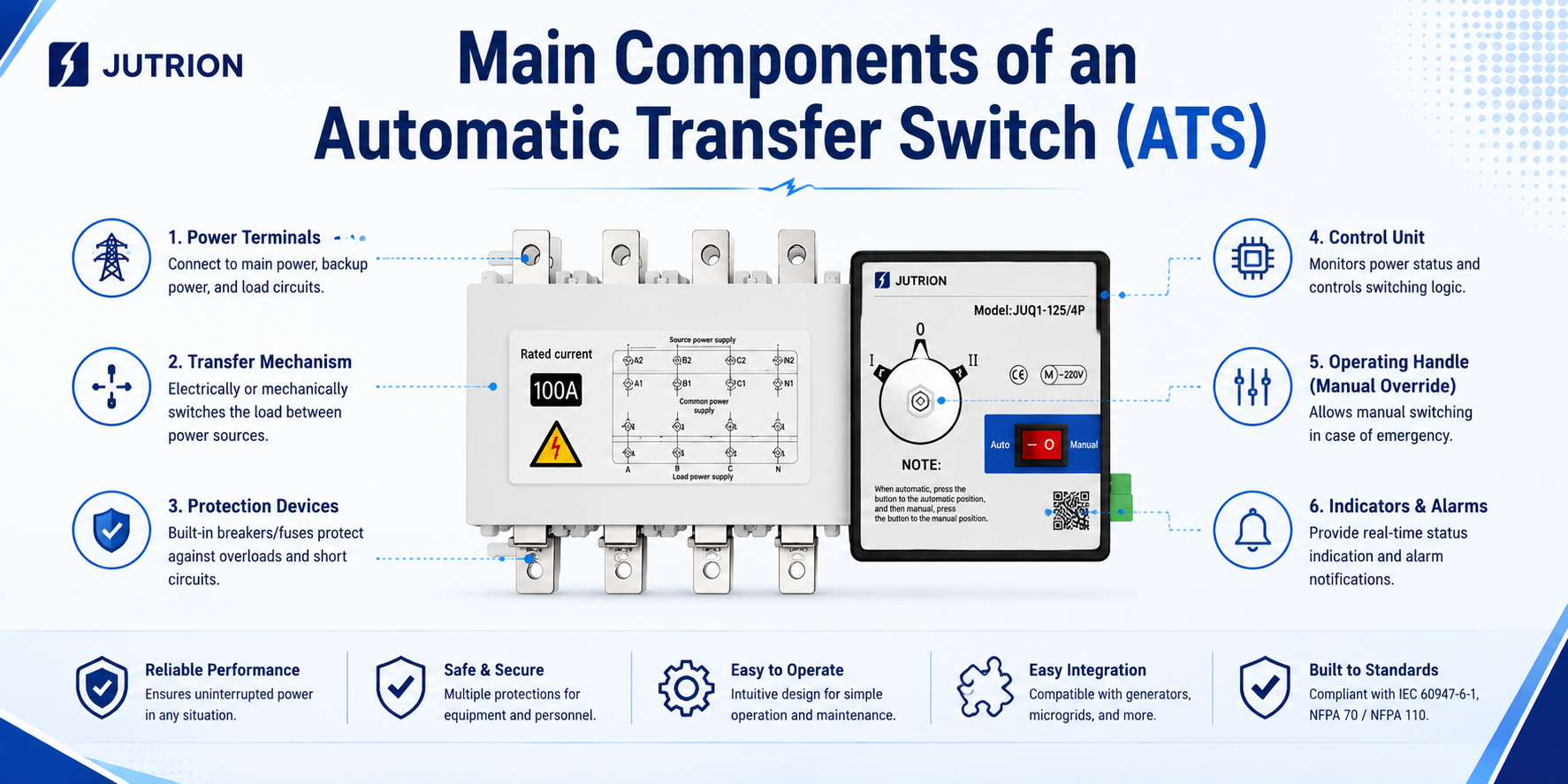
ATS không phải là một thiết bị chuyển mạch đơn lẻ, mà là một hệ thống hoàn chỉnh tích hợp giám sát, điều khiển, vận hành và bảo vệ an toàn. Các thành phần cốt lõi của nó chủ yếu được chia thành bốn mô-đun chính, cùng nhau thực hiện toàn bộ quá trình giám sát trạng thái nguồn điện, phát hiện sự cố, chuyển nguồn an toàn và tự động chuyển nguồn trở lại, như sau:
Khối chuyển mạch nguồn kép (Cơ cấu chấp hành)
Đây là khối thực thi lõi của ATS, chịu trách nhiệm chuyển đổi vật lý giữa nguồn điện chính và nguồn điện dự phòng. Nó thường được chia thành hai dạng chính:
- ATS cấp PC tích hợp: a single integrated transfer switch with a dedicated mechanical interlocking structure, designed to achieve a “break-before-make” operation. It can withstand relatively high short-circuit current and is widely used in critical-load applications.
- CB Class ATS: composed of two circuit breakers (or isolating switches) together with mechanical and/or electrical interlocking. It provides both protection and transfer functions, usually at a lower cost, and is commonly used for generally important loads.
2. Intelligent Controller (Control Brain)
This is the “decision-making center” of the ATS, responsible for power status monitoring and transfer logic control:
- Real-time monitoring of parameters of both power sources, such as voltage, frequency, phase loss, overvoltage, and undervoltage;
- Execution of logic such as delay confirmation (to prevent false operation), fault transfer, retransfer from backup to main supply, and generator start/stop coordination;
- Provision of functions such as local/remote control, status indication, fault alarm, and communication interfaces (such as Modbus).
3. Driving and Interlocking Mechanism (Safety Core)
- Driving mechanism: may be motor-operated, electromagnetic, or spring energy-storage type, providing the switching force for the switch body and ensuring reliable operation;
- Interlocking mechanism: adopts both mechanical and electrical interlocking to strictly prevent the main and backup power sources from being closed at the same time, completely avoiding short circuits and circulating current accidents between the two sources. This is the key safety design that distinguishes an ATS from an ordinary dual-switch arrangement.
4. Auxiliary and Supporting Components
- Power sampling unit: provides the controller with voltage and current signals from the two power sources
- Status feedback contacts: feed back the opening/closing position of the switch and fault status to the external system
- Generator control interface: some ATS units can directly output signals to control generator start and stop, enabling the generator to start automatically and supply power when the utility power fails;
- Operating panel / display screen: used for parameter setting, manual/automatic transfer control, and operating status display.
Supplementary Note:
The differences in the core components of different types of ATS are essentially different implementation forms under IEC standards. For example, the differences between PC Class ATS and CB Class ATS are mainly reflected in the structural design of the switch body and the level of protection capability, while the design logic of core safety modules such as the controller and interlocking mechanism must all comply with the mandatory requirements of the applicable standards.
Quick ATS Selection Checklist
✅ Load category and application scenario confirmed
✅ Rated current and frame size meet load and short-circuit requirements
✅ Number of poles (3P/4P) matches the system configuration
✅ ATS type (PC Class / CB Class) matches the required load reliability level
✅ Control mode and delay parameters can be adjusted according to site conditions
✅ Additional functions (interlocking / communication / bypass) configured as needed
✅ Coordination logic with upstream and downstream protection devices, generator, and fire protection system is clearly defined
Start with the Application: Define the Load Level and Project Requirements First
Confirm the Core Parameters: Prioritize the Key Indicators
1. Rated Current and Frame Size
- Rated current (Ie): should be at least 1.25 times the calculated load current, taking into account starting current and long-term operating margin. For example, if the load current is 160A, a 200A or 250A ATS should be selected.
- Frame size: should be selected according to the system short-circuit current and must meet the requirement for rated short-time withstand current (Icw), in order to avoid burnout under fault conditions.
2. Pole Selection (P)
- 3P ATS: suitable for three-phase three-wire systems, where the neutral conductor does not participate in switching. It is applicable to TN/IT systems and generally offers lower cost.
- 4P ATS: suitable for three-phase four-wire systems, where the neutral conductor is switched simultaneously. It is applicable to scenarios involving neutral shift, severe harmonic distortion, or non-common neutral between two power sources (such as hospitals and data centers), helping avoid neutral circulating current.
Type Selection: PC Class vs CB Class (Core Differences)
| Dimension | PC Class ATS | CB Class ATS |
| Core structure | Integrated transfer switch with dedicated mechanical interlocking | Two circuit breakers with interlocking mechanism |
| Protection function | Transfer function only, without short-circuit or overload protection | Built-in circuit breaker protection, capable of short-circuit interruption |
| Short-circuit withstand capability | High, able to withstand large short-time current impact | Depends on the breaking capacity of the circuit breakers and requires coordination with upstream and downstream protection |
| Transfer speed | Faster, typically 10–50 ms | Slower, typically 100–500 ms |
| Typical applications | Critical loads, generator power supply, and systems with high short-circuit current | Generally important loads and applications requiring built-in protection |
Control and Transfer Modes
- Control modes: automatic (priority), manual, and remote control (Modbus / dry contact), to be selected according to operation and maintenance requirements.
- Transfer modes:
Automatic transfer and automatic retransfer: after the main power source recovers, the load is automatically transferred back to utility power. This is suitable for applications where utility power is the preferred source.
Automatic transfer without automatic retransfer: after switching to the backup power source, the ATS remains in that state and requires manual reset. This is suitable for applications where utility power quality is poor or fluctuates frequently. - Delay settings: fault confirmation delay (to filter out momentary fluctuations), generator start delay, and utility power recovery delay should all be adjusted according to actual site conditions.
Additional Functional Requirements
- Generator linkage: can directly output start/stop signals to enable automatic generator startup when utility power fails.
- Bypass function: supports online maintenance of the ATS without interrupting the load power supply, suitable for high-reliability applications.
- Communication function: Modbus/RS485 interfaces allow integration with building automation or power monitoring systems.
- Fire protection linkage: supports forced fire control logic and disconnects the power supply to non-firefighting loads in the event of a fire.
Key Pitfalls to Avoid During ATS Selection
- Neutral handling: for 4P ATS, special attention should be paid to the switching sequence of the neutral conductor to avoid load overvoltage caused by opening the neutral before closing it again. In TN-S systems, if the neutrals of both power sources share a common grounding point, a 3P+N solution (neutral makes first and breaks last) may be considered first.
- Short-circuit protection coordination: the interrupting capacity of the circuit breakers used in CB Class ATS must be higher than the prospective short-circuit current of the system, and selective coordination with the upstream circuit breaker should also be achieved to avoid nuisance tripping at higher levels.
- Transfer time coordination: for critical loads, such as those located downstream of a UPS, it is necessary to confirm whether the ATS transfer time is within the acceptable range of the load, so as to avoid UPS battery discharge or load restart caused by the transfer process.
- Environmental adaptability: in high-temperature, humid, or dusty environments, models with an IP protection rating of at least IP40 should be selected, and cabinet ventilation or dehumidification devices should be added when necessary.
Environmental adaptability: in high-temperature, humid, or dusty environments, models with an IP protection rating of IP40 or above should be selected, and cabinet ventilation or dehumidification devices should be added when necessary.
PC Class vs CB Class ATS: What’s the Difference?
PC Class Automatic Transfer Switch
Standard definition: a transfer switching device that is only capable of making, carrying the rated operating current, and withstanding the rated short-time current, but does not have the ability to interrupt short-circuit current.
Product positioning: a device dedicated purely to power source transfer. It does not include overload or short-circuit trip protection mechanisms. Its core function is only to ensure reliable transfer between two power sources, while system fault protection is provided by upstream devices such as circuit breakers and fuses.
CB Class Automatic Transfer Switch
Standard definition: a transfer switching device equipped with an overcurrent trip device, whose contacts are capable of making and carrying current, and which can also directly interrupt short-circuit fault current.
Product positioning: composed of two circuit breakers together with an interlocking mechanism, it combines both power source transfer and overload/short-circuit fault protection functions, and can itself interrupt fault current in the circuit.
Typical Applications of PC Class ATS
- Critical Level 1 loads such as hospitals, data centers, and financial server rooms, where power interruption may lead to major losses;
- Emergency power supply circuits for fire pumps, smoke exhaust fans, and other firefighting systems;
- Dual-power supply systems used together with generator sets;
- Precision industrial control production lines with extremely high requirements for outage duration and transfer stability.
Typical Applications of CB Class ATS
- Level 2 power supply loads in office buildings, shopping malls, and general commercial buildings;
- Small equipment rooms, emergency lighting, and residential backup power supply;
- Conventional power distribution projects with limited budget and relatively low short-circuit current in the circuit.
Key Considerations for Selection
- PC Class ATS must be coordinated with upstream protective devices and cannot be used alone as a fault protection switch;
- CB Class ATS usually has a longer transfer time, so it should be used with caution for sensitive electronic loads to prevent unexpected shutdown or restart of equipment;
- In many locations, fire protection codes require the use of PC Class ATS to ensure that emergency power supply remains effective.
If your project involves upstream protection coordination, you may also refer to our MCCB product page and ACB product page for more information on protection coordination and system matching.
ATS Installation and Wiring Considerations
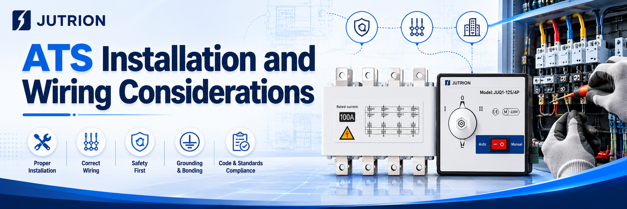
Key Installation Requirements
Installation environment:
Avoid humid, dusty, corrosive gas, and strong vibration areas. The ambient temperature should be controlled within -25°C to +40°C, the cabinet should have good ventilation and heat dissipation, and the protection rating should match the actual site conditions.
Installation fixing:
Install the ATS vertically in the upright position. The cabinet should remain level and stable, with sufficient space reserved for inspection and operation. Inclined or inverted installation is strictly prohibited. When multiple units are arranged together, adequate spacing for heat dissipation should be reserved.
Safety clearance:
Standard electrical clearance should be maintained between different phase conductors and between incoming and outgoing lines. The insulation withstand requirements must be met to prevent creepage and phase-to-phase discharge.
Grounding requirements:
The equipment enclosure and cabinet must be reliably grounded. The grounding conductor specification should comply with the applicable electrical code requirements to eliminate potential electric leakage hazards.
Core Wiring Requirements
Phase sequence verification:
Strictly distinguish the incoming phase sequence of the normal power source and the backup power source, and ensure that the phase positions of both power sources are consistent. Incorrect phase sequence may cause transfer failure or equipment damage.
Separation of incoming and outgoing lines:
The incoming terminals are connected to the main and backup power sources, while the outgoing terminals are uniformly connected to the downstream load. Reverse wiring or mixed wiring is not allowed. Wiring must follow the terminal layout and identification marks of the equipment.
Cable selection:
The conductor current-carrying capacity must be greater than the rated current of the switch, and should meet the requirements for voltage drop and temperature rise. Wiring terminals must be firmly tightened to prevent false contact and overheating caused by looseness.
Neutral conductor handling:
3P/4P switches must be wired according to the system configuration. The neutral conductors of the two power sources must never be mixed or incorrectly connected, so as to avoid neutral circulating current and voltage shift problems.
Control circuits:
Secondary control wiring should be arranged neatly, with strong-current and weak-current circuits routed separately to reduce electromagnetic interference. Interlocking, communication, and generator start/stop circuits must be wired according to the drawings.
Inspection and Commissioning After Wiring
- Before energizing, check whether there is any short circuit, incorrect wiring, or missed connection, and tighten all wiring points.
- Test the automatic transfer function and manual transfer function in sequence, and verify that the actions of fault power-off and utility power recovery transfer-back are normal.
- Verify the delay parameters, protection logic, and interlocking signals to ensure they are consistent with the design scheme.
- During trial operation, observe the temperature rise of the switch, abnormal noise, and indicator light status. The ATS can only be put into formal operation when no abnormality is found.
Prohibited Actions
It is strictly forbidden to dismantle the mechanical and electrical interlocking mechanism without authorization; it is prohibited to manually close the two power sources in parallel; overload connection to the load is not allowed; and it is strictly forbidden to open the cover for wiring or disassembly while energized.
Common ATS Selection Mistakes and Troubleshooting Resources
The most common selection mistakes include choosing the ATS only according to load current without leaving a margin, mistaking an ATS for a UPS, failing to verify the pole configuration, overlooking generator start signal requirements, ignoring generator voltage build-up delay, failing to consider high-temperature derating, and directly applying a conventional generator-based solution to solar PV or energy storage systems.
Key Takeaways:
If ATS is treated simply as “just another ordinary switch to buy,” it will almost certainly create hidden risks later, such as wiring confusion, incorrect transfer actions, and even improper upstream tripping. A selection logic that can truly stand up to real-world testing must always follow this principle: define the system boundaries first, and then define the product parameters. Only after the system structure and application scenario are clearly understood should the pole configuration, control strategy, and protection coordination be determined, so that the final product model can be selected accurately.
Different types of projects have fundamentally different technical demands for ATS:
Residential buildings and commercial complexes: the core requirement is absolute reliability of basic switching action together with a balanced budget.
Large industrial facilities and critical infrastructure: priority must be given to upstream and downstream protection coordination, as well as the ability to withstand extreme short-circuit fault conditions.
Renewable energy and microgrid systems: low-level control logic compatibility and inverter coordination have become new technical priorities.
Therefore, it is meaningless to discuss ATS selection without reference to the actual system architecture. That is the essence of engineering design: there is no “one-size-fits-all” model here, only a solution tailored specifically to your system.
There is no universal ATS solution for every project. If you need help evaluating your system architecture, pole configuration, or protection coordination, you are welcome to contact our engineering team for professional support.
Frequently Asked Questions About ATS:
Q: If a PC Class ATS is used, is an upstream circuit breaker such as an MCCB or ACB still required?
A:Yes, it is absolutely necessary. A PC Class ATS is like the “railway switch operator” in a power distribution system: it is only responsible for changing the track, that is, switching the power source, but it is not responsible for braking, that is, interrupting short-circuit faults.
When a severe short circuit occurs, it can only withstand the extremely high rated short-time withstand current (Icw) for a short period, while waiting for the upstream MCCB or ACB to trip and clear the fault.
Without a circuit breaker acting as its protection, a PC Class ATS is very dangerous under short-circuit conditions.
Q:How should the rated current be selected? Is it enough to simply add up the load power shown on the drawings?
A:Never select it right at full-load current. Real engineering conditions are far more complicated than theoretical calculations. If the temperature inside the distribution cabinet rises to 50°C or even 60°C in summer, the equipment must operate under derating conditions. In addition, inductive loads such as pumps and fans can produce high inrush current during startup. For this reason, we usually recommend leaving at least a 20% safety margin above the actual maximum operating current.
Q:Can two power sources with different voltage levels share the same ATS?
A:This is strongly not recommended unless a specially customized controller is used. The ATS controller usually needs to sample the voltage of both power sources at the same time for comparison and decision-making. If the two power sources are not at the same voltage level, the control logic may become completely disordered.
In standard engineering practice, the proper solution is to first unify the voltage reference through a transformer and then perform the transfer.
