

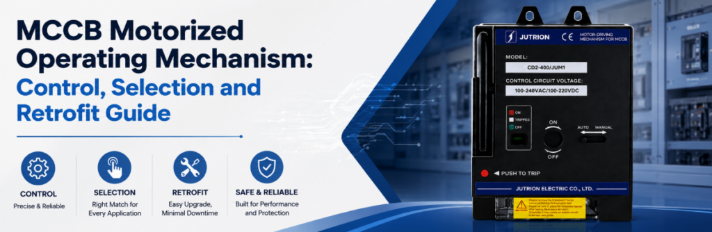
Hướng dẫn điều khiển, lựa chọn và trang bị thêm cơ cấu vận hành bằng động cơ MCCBTrả lời nhanh: Cơ cấu vận hành bằng động cơ MCCB làm gì?
Cơ cấu vận hành bằng động cơ MCCB, còn được gọi là bộ vận hành động cơ MCCB, là một bộ truyền động điện di chuyển bộ ngắt mạch dạng khối tương thích giữa các trạng thái cơ học theo lệnh. Tùy thuộc vào bộ ngắt và cơ cấu phù hợp, nó có thể đóng, mở và đặt lại bộ ngắt sau khi ngắt. Đây là phụ kiện bộ ngắt duy nhất có thể đóng bộ ngắt từ xa — cuộn cắt và cuộn thấp áp chỉ có thể mở bộ ngắt.
Phòng điều khiển gửi lệnh ĐÓNG đến bộ ngắt nguồn cấp và không có gì xảy ra. Giả định đầu tiên thường là động cơ bị hỏng. Động cơ thường vẫn khỏe mạnh: bộ ngắt có thể vẫn ở trạng thái ĐÃ NGẮT, bộ chọn có thể ở chế độ BẰNG TAY, có thể thiếu điều kiện cho phép đóng, hoặc nguồn điều khiển có thể sụt áp trong quá trình vận hành.
Đó là điểm trọng tâm của hướng dẫn này. Bộ vận hành động cơ không phải là bàn tay điện xoay tay cầm. Nó là một mắt xích trong chuỗi: hệ thống tự động hóa phát lệnh, logic cho phép quyết định lệnh có được phép hay không, cơ cấu di chuyển bộ ngắt, và tiếp điểm phụ xác nhận kết quả. Nếu bất kỳ mắt xích nào không được chỉ rõ, “vận hành MCCB từ xa” không phải là một chức năng hoàn chỉnh.
Bộ vận hành động cơ cũng không phải là thiết bị bảo vệ. Nó không cảm nhận dòng điện, không ngắt khi có sự cố, và không làm tăng Iđóng của bộ ngắt hoặc thay đổi bộ phận ngắt của nó. Nó cũng không thay thế công tắc tơ: bộ ngắt có bộ vận hành động cơ được chế tạo cho vận hành không thường xuyên, không phải cho hàng nghìn chu kỳ mỗi ngày mà mạch động cơ yêu cầu.
Sử dụng hướng dẫn này theo ba lượt:
- Xác nhận dự án chỉ cần mở từ xa, hay cũng cần đặt lại và đóng từ xa.
- Kiểm tra tính tương thích cơ khí, điện áp điều khiển, nhu cầu dòng khởi động và sụt áp cáp.
- Xác định các điều kiện cho phép, phản hồi, khóa liên động và hành vi sau khi ngắt bảo vệ.
Thông số kỹ thuật tóm tắt
| Quyết định | Yếu tố quyết định | Sai lầm thường gặp của người mua |
|---|---|---|
| Loại phụ kiện | Có cần đóng từ xa hay không, không chỉ ngắt Đặt mua cuộn cắt cho "điều khiển từ xa" | Chuyển động yêu cầu“ |
| Chỉ mở, hoặc mở–đặt lại–đóng sau khi ngắt | Cho rằng "đóng từ xa" bao gồm đặt lại từ trạng thái ĐÃ NGẮT | Độ khớp cơ khí |
| Dòng bộ ngắt, khung, số cực và cách lắp — từ nhãn máy | Chỉ khớp theo định mức ampe | Điện áp điều khiển |
| Sụt áp trên chiều dài cáp thực tế | Chọn 24 V DC theo thói quen cho đường dây dài | Kích cỡ nguồn điều khiển |
| Tổng VA khởi động (dòng xung) cộng với biên dự phòng nguồn của dự án | Tính kích cỡ theo tải duy trì | Phản hồi |
| Tiếp điểm vị trí cộng với tiếp điểm ngắt/báo động riêng | Một tiếp điểm phụ cho mọi thứ | Chế độ làm việc |
| Số lần vận hành mỗi năm so với độ bền định mức | Dùng bộ ngắt ở nơi cần công tắc tơ | Vận hành từ xa bắt đầu với ba trạng thái của bộ ngắt, không phải hai |
Công tắc thủ công là BẬT hoặc TẮT. MCCB có trạng thái thứ ba chi phối mọi thiết kế điều khiển từ xa: ĐÃ NGẮT. Lệnh đóng không thể xử lý bộ ngắt đã ngắt như thể nó chỉ đơn giản là đang mở.
BẬT.
nghĩa là các tiếp điểm chính đã đóng. Bộ vận hành động cơ không nên nhận lệnh đóng lặp lại khi bộ ngắt đã đóng, đó là lý do phản hồi vị trí đáng tin cậy hơn việc cho rằng lệnh cuối cùng đã thành công. TẮT.
nghĩa là các tiếp điểm đang mở và cơ cấu sẵn sàng cho thao tác đóng bình thường nếu các điều kiện cho phép được thỏa mãn. Chỉ báo TẮT không chứng minh mạch an toàn để làm việc; cách ly, khóa và xác nhận không còn điện vẫn là các yêu cầu riêng biệt. nghĩa là các tiếp điểm đang mở và cơ cấu sẵn sàng cho thao tác đóng bình thường nếu các điều kiện cho phép được thỏa mãn. Chỉ báo TẮT không chứng minh mạch an toàn để làm việc; cách ly, khóa và xác nhận không còn điện vẫn là các yêu cầu riêng biệt.
VẤP NGÃ có nghĩa là cơ cấu đã phản hồi với một giải phóng bảo vệ hoặc lệnh cắt. Trước khi máy cắt có thể đóng lại, cơ cấu thường phải di chuyển qua một hành trình đặt lại. Một lần cắt do sự cố là thông tin, không chỉ đơn thuần là vị trí tay cầm khác.
| Trạng thái quan sát được | Ý nghĩa đối với hệ thống điều khiển | Hành động tiếp theo được phép | Phản hồi cần có |
|---|---|---|---|
| nghĩa là các tiếp điểm chính đã đóng. Bộ vận hành động cơ không nên nhận lệnh đóng lặp lại khi bộ ngắt đã đóng, đó là lý do phản hồi vị trí đáng tin cậy hơn việc cho rằng lệnh cuối cùng đã thành công. | Tiếp điểm chính đã đóng | Giữ, hoặc phát lệnh MỞ khi cần | Tiếp điểm vị trí |
| nghĩa là các tiếp điểm đang mở và cơ cấu sẵn sàng cho thao tác đóng bình thường nếu các điều kiện cho phép được thỏa mãn. Chỉ báo TẮT không chứng minh mạch an toàn để làm việc; cách ly, khóa và xác nhận không còn điện vẫn là các yêu cầu riêng biệt. | Tiếp điểm mở, cơ cấu sẵn sàng đóng | CHỈ ĐÓNG khi các điều kiện cho phép đều đúng | Chỉ báo vị trí mở và trạng thái cho phép đóng |
| VẤP NGÃ | Một lần cắt bảo vệ hoặc cắt từ xa đã tác động | Điều tra, đặt lại nếu được phép, sau đó đánh giá lại việc đóng | Chỉ báo cắt/báo động khác biệt với trạng thái TẮT bình thường |
| Đang di chuyển hoặc chưa xác nhận | Cơ cấu đang vận hành, bị kẹt, hoặc phản hồi không nhất quán | Chặn các lệnh tiếp theo cho đến khi hết thời gian chờ và chẩn đoán | Bộ định thời lệnh cộng với so sánh vị trí |
Hành Trình Đặt Lại Là Một Yêu Cầu Cơ Khí Riêng Biệt
Sau một lần cắt bảo vệ, nhiều máy cắt yêu cầu tay cầm phải di chuyển vượt quá vị trí TẮT bình thường trước khi cơ cấu đặt lại. Một bộ truyền động động cơ chỉ dành cho chuyển mạch BẬT/TẮT có thể không cung cấp hành trình đó. Hãy chỉ rõ “đặt lại từ xa sau khi cắt” một cách tường minh thay vì mặc định rằng nó đã bao gồm trong “đóng từ xa”.
Việc đặt lại cũng thay đổi logic phản hồi. Một tiếp điểm báo động có thể xóa khi cơ cấu đặt lại, trong khi một tiếp điểm phụ TẮT có thể đã cho thấy trạng thái tiếp điểm chính mở. Nếu bộ điều khiển chỉ dùng TẮT làm bằng chứng, nó có thể phát lệnh ĐÓNG trong khi máy cắt vẫn còn bị cắt về mặt cơ khí.
Bộ Truyền Động Động Cơ, Cuộn Cắt hoặc Cuộn Thấp Áp: Chọn Phụ Kiện Phù Hợp Với Công Việc
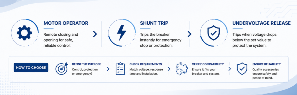
Bộ truyền động động cơ so với cuộn cắt so với cuộn thấp áp để chọn phụ kiện MCCBĐiều khiển từ xa thường bị chỉ định quá mức vì các phụ kiện này bị coi là có thể thay thế cho nhau. Chúng bổ trợ cho nhau, và hiểu lầm đắt đỏ nhất trong nhóm này là mua một cuộn cắt và phát hiện ra nó không thể đóng máy cắt lại.
| Khả năng | Bộ truyền động động cơ | Cuộn cắt (MX) | Cuộn thấp áp (MN) | Tiếp điểm phụ (OF) |
|---|---|---|---|---|
| Đóng máy cắt từ xa | Có, khi thiết kế phù hợp cho phép | Không | Không | Không |
| Mở máy cắt từ xa | Có | Có | Có, khi mất nguồn | Không |
| Đặt lại sau khi cắt | Tùy từng model — cần xác nhận | Không | Không | Không |
| Báo vị trí máy cắt | Không tự nó | Không | Không | Có |
| Cần nguồn cấp liên tục | Không — chỉ tiêu thụ khi vận hành | Không — chỉ được cấp điện để cắt | Có — được giữ cấp điện | Không — tiếp điểm khô |
| Khi mất nguồn điều khiển | Máy cắt giữ trạng thái; không có điều khiển từ xa | Không thể cắt | Cắt — an toàn theo bản chất | Trạng thái tiếp điểm không đổi |
| Vai trò điển hình | Bộ truyền động mở, đặt lại và đóng từ xa | Đường cắt báo cháy hoặc khẩn cấp | Fail-safe trip and close permission | Command confirmation and interlocking |
Read the last two rows together. A shunt trip needs a healthy control supply to do its job; an undervoltage release does its job precisely when the supply is lost. Choose between them by asking what should happen if the control supply itself fails. A motor operator answers a different question: who closes the breaker when nobody is standing in front of it.
A motor operator may open the breaker mechanically and the project may still require a shunt trip, because protection or emergency circuits often need an independent, defined trip path. They are fitted together, not chosen between.
How a Motor Operator Actually Moves the Breaker
The command reaches the mechanism, a geared motor runs, and the breaker changes state. What happens between those points varies by design, and the difference affects command duration, timing and what the controller should expect after a power loss.
Direct drive. The motor moves the operating interface through the complete stroke while it is energised. The command must last long enough for the full travel, and the actuator movement broadly follows the breaker handle, which makes the operation easy to observe during commissioning.
Stored energy. The motor charges a spring, and the spring is then released to move the contacts in one fast action. This decouples contact speed from motor speed, which is what allows the contacts to close quickly enough to limit pre-arcing. The charging sequence and the contact operation are two separate events, and the controller should allow for both.
Neither approach is universally better. The decisive question is whether the complete breaker-and-mechanism assembly performs the required open, reset and close sequence on the available control supply and within the project timing. In both cases the motor stops once the operation completes, which is why a motor operator presents a large momentary demand and effectively no standing load.
Manual operation must remain defined either way. The current JUTRION portfolio page lists a built-in Auto/Manual switch for its motorised operating mechanism range. Confirm the ordered model’s mechanical engagement, whether MANUAL blocks remote commands, whether it disconnects motor power, and whether the controller receives selector-position feedback. A manual selector is not an isolation device and must be coordinated with the panel’s locking procedure.
Build the Command, Permission, Motion and Feedback Chain
A dependable motor-control circuit has four linked functions. Each needs a defined input, output, failure response and commissioning test.
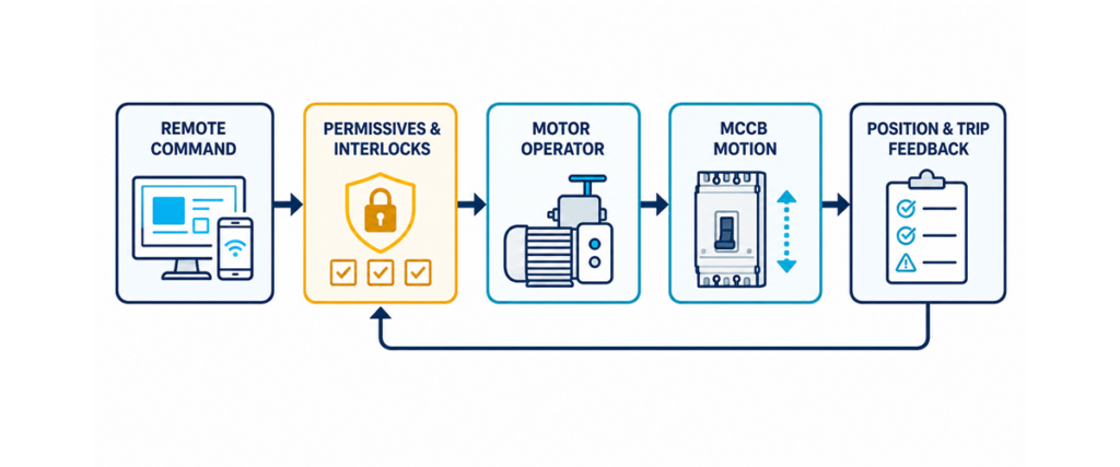
MCCB motorized operating mechanism control chain showing remote command, permissives and interlocks, breaker motion, and position and trip feedback.Command
- The command may come from local pushbuttons, a PLC output, a BMS relay, a transfer controller or a protection relay. Define whether the mechanism expects a pulse, a maintained signal, or separate OPEN and CLOSE inputs. Do not infer the arrangement from the control voltage. Commands must be mutually exclusive: if OPEN and CLOSE can be energised together through relay overlap or a software error, the circuit must resolve the conflict predictably.
Permission
- A command is a request, not authority to energise a circuit. Close permissives typically include healthy source voltage, no lockout active, breaker not in maintenance, alternate source open, trip cause cleared, and the selector in REMOTE. Opening usually has fewer permissives, but the required logic still belongs in the project cause-and-effect document rather than in an installer’s judgement.
Motion
- Once permitted, the mechanism draws control power and moves the breaker. The supply must hold its voltage through that transient demand. A supply that measures correctly at rest can dip when the motor starts, leaving the operation incomplete. Allow the manufacturer-declared operating time plus a supervision margin, and never issue rapid repeated commands to force completion.
Tiếp điểm vị trí cộng với tiếp điểm ngắt/báo động riêng
- Confirm the physical state after the command. A position contact indicates ON or OFF; a separate alarm contact distinguishes a protective trip from a commanded opening. If the command expires without the expected state, raise a failure-to-open or failure-to-close alarm and block retries. That turns a silent failure into actionable diagnostic information.
Size the Control Supply on the Pickup Surge, Not the Holding Load
This is the calculation most often skipped, and it separates a panel that works from one that fails intermittently. Accessory coils draw two very different currents.
- Pickup (inrush) VA — the brief surge as the coil energises and the motor starts. It sets the momentary capability the supply needs and the voltage dip every other device on that supply will see.
- Holding VA — the continuous draw once energised. It sets the steady thermal load.
A supply that comfortably carries the holding load but sags during pickup will let the coil drop out, or prevent it pulling in at all. The device is not faulty; the supply is undersized for a demand lasting a fraction of a second.
Peak (pickup) demand:
Peak VA = Σ (pickup VA × quantity)
Peak current at the coil voltage:
Ipeak = Peak VA / V
Steady (holding) demand:
Steady VA = Σ (holding VA × quantity)
Recommended supply rating:
Illustrative first-pass supply = Peak VA × 1.25
The 1.25 multiplier is the illustrative allowance used by the JUTRION calculator, not a universal requirement stated by IEC 60947-2. Replace it where the power-supply manufacturer, control-transformer data, project standard, duty, temperature, or simultaneous-operation study requires a different margin.
Where several accessories can energise together — a motor operator running its cycle while an undervoltage release is held in — add their pickup figures. That combination, not any single device, is the worst case. The JUTRION breaker accessory power calculator runs these equations directly.
| Phụ kiện | Pickup (VA) | Duy trì (VA) | Số lần vận hành mỗi năm so với độ bền định mức |
|---|---|---|---|
| Bộ truyền động động cơ | Approx. 300–600 | 0 | Draws only during the operating cycle |
| Cuộn cắt (MX) | Approx. 100–300 | 0 | Tức thời; chỉ được cấp điện để cắt |
| Cuộn thấp áp (MN) | Approx. 200–350 | Approx. 5–10 | Continuously energised |
| Tiếp điểm phụ / báo động | Negligible | Negligible | Volt-free contact |
These are the illustrative default ranges published by the JUTRION calculator, not IEC values or ordered-product ratings. Coil demand varies by series, frame and AC or DC type, so replace every default with the datasheet figure for the device actually ordered. The table is useful for understanding pickup versus holding duty, not for issuing a final transformer or power-supply specification.
Check the Volt Drop Before Choosing a 24 V DC Coil
Low-voltage DC is often specified for compatibility with a PLC rail or a UPS-backed control supply. For a motor operator it deserves a second look: the same power at a lower voltage means proportionally more current, and volt drop rises with it.
For a two-wire DC control circuit:
ΔU = 2 × L × I × ρ / A
Where ΔU is volt drop in V, L is the one-way run in m, I is the operating current in A, ρ is copper resistivity (about 0.0175 Ω·mm²/m at 20 °C, rising with temperature) and A is conductor area in mm². Rearranged for the permissible run:
Lmax = ΔU × A / (2 × I × ρ)
For an illustrative comparison, assume a mechanism with a 450 VA pickup demand and allow a 10% drop. The 450 VA value is a constructed input within the calculator’s typical range, not a JUTRION model rating:
| Coil voltage | Pickup current | Permitted drop | Max. run on 2.5 mm² | Max. run on 6 mm² |
|---|---|---|---|---|
| DC 24 V | 18.8 A | 2.4 V | Approx. 9 m | Approx. 22 m |
| DC 110 V | 4.1 A | 11 V | Approx. 192 m | Approx. 460 m |
| AC 220 V | 2.0 A | 22 V | Approx. 768 m | Approx. 1844 m |
Under these specific assumptions, the 24 V DC option on 2.5 mm² conductor reaches the 10% drop allowance at roughly nine metres. This is not a universal cable-length limit: the result changes directly with the ordered mechanism’s pickup demand, conductor size, temperature, terminal losses, and permitted operating-voltage range. For long control-room runs, compare a larger conductor, a local supply at the breaker, and a higher control voltage.
This is why accessory coils are offered across such a wide voltage range. JUTRION motorised operating mechanisms are available in AC 110 V, AC 220 V and AC 400 V, and in DC 24 V, DC 36 V, DC 110 V and DC 220 V, so the control voltage can be chosen to suit the cable run rather than the cable being sized around a voltage chosen by habit.
A Worked Example: 400 A Feeder with a Remote Motor Operator
The application. A 400 A MCCB feeds a pumping station from a control room about 60 m away. The breaker must be opened, reset and closed remotely. An undervoltage release is fitted so the breaker trips on loss of the control supply.
Step 1 — list what can energise together. The motor operator runs its cycle while the undervoltage release is held in. Both sit on the same control supply, so both count.
Step 2 — define illustrative inputs. Assume a motor operator at 450 VA pickup / 0 holding and an undervoltage release at 275 VA pickup / 7 VA holding. These constructed values sit within the JUTRION calculator’s illustrative ranges; replace them with the ordered accessory datasheets.
Step 3 — peak demand.
Peak VA = (450 × 1) + (275 × 1) = 725 VA
Step 4 — steady demand.
Steady VA = (0 × 1) + (7 × 1) = 7 VA
The ratio is the lesson: the momentary demand is more than a hundred times the continuous one.
Step 5 — size the supply.
Illustrative supply = 725 × 1.25 = 906 VA
Step 6 — check the voltage against the run. At DC 24 V the peak current is 725 / 24 = 30.2 A, and holding a 10 % drop over 60 m would need roughly 26 mm² — impractical for a control circuit. At AC 220 V the peak is 725 / 220 = 3.3 A and 2.5 mm² is comfortable with margin.
Illustrative result: AC 220 V is the more practical option for the assumed 60 m run. A control transformer around 1 kVA and 2.5 mm² conductors are the first-pass result under the stated inputs; final selection requires the transformer’s short-time regulation, protection, installation method, temperature, actual accessory data, and permitted voltage range. At DC 24 V, this example points toward a local supply or a substantially larger conductor.
Automatic Closing Needs Permissives, Interlocks and a Reset Policy
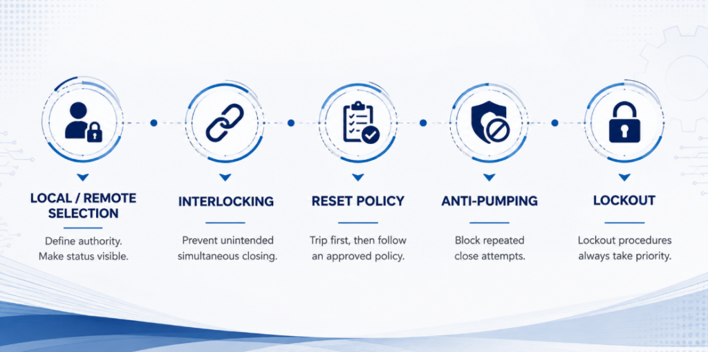
Automatic closing permissives, source interlocking, reset policy, anti-pumping and maintenance lockoutRemote opening is straightforward. Remote closing can energise damaged equipment, restart machinery, parallel sources, or expose people who believed a circuit would stay open. The close path deserves more engineering attention than the motor.
Local/remote selection. A selector defines who has authority. Its state should be visible to the controller, so a blocked command produces a clear “local mode” indication rather than a generic failure alarm.
Source interlocking. Where two breakers select between utility, generator or bus sources, logic must prevent unintended simultaneous closing unless the system is designed to parallel. Mechanical interlocking adds a physical layer, but its compatibility must be verified with the chosen breakers and mechanisms.
Reset and reclose policy. A protective trip should normally block automatic closing until the cause is classified. Some systems permit one supervised reclose for a defined transient; others require investigation after every trip. The motor operator executes the approved policy — it should not create one by default.
Anti-pumping. If a CLOSE command remains present while the breaker trips, the system must not cycle between closing and tripping. The control architecture should block repeated attempts until the command is removed and a new authorised sequence begins.
Maintenance lockout. Software inhibition is not a substitute for an approved lockout procedure. A remote system can issue commands unexpectedly during testing, communication recovery or a software restart.
Apply the Logic to Three Common Architectures
Generator and Source Transfer
Two breakers, each with a motor operator, are switched by a transfer controller so that only one is ever closed. A motor operator is essential because the controller must đóng a breaker, not merely trip one.
The controller opens the active source, confirms it is open through position feedback, and only then permits the alternate source to close. Interlocking is mandatory. The control supply must also be available from whichever source is live — a detail easily missed when the control transformer is fed from the utility side alone.
Key distinction: a motor operator supplies motion; it does not by itself make two breakers a transfer switch.
Unattended Site or Remote Substation
A breaker in a rooftop plant room, a pumping station or an unmanned substation is motorised so a trip can be investigated and supply restored without a site visit. The cable run is usually long, which makes the control-voltage decision the governing constraint rather than the mechanism. Fit an alarm contact alongside the position contact so the control system can distinguish a fault trip from a commanded opening before anyone attempts a remote reset.
Load Shedding and Scheduled Switching
An energy-management system opens non-critical feeders when generator capacity or site demand reaches a limit, then restores them in stages to avoid a second demand peak. Each feeder needs a priority, a minimum off time, a close permissive and a failure alarm.
One opening and one closing movement per day totals about 10,950 movements over fifteen years. Confirm how the ordered mechanism defines an operation or cycle before comparing this figure with endurance. Frequent routine switching may belong to a contactor, with the breaker left to provide protection and isolation.
Retrofitting a Motor Operator to a Breaker Already Installed
Most writing on this subject assumes breaker and accessory are specified together. A large share of real enquiries are the opposite: the breaker has been in service for years, the requirement for remote operation appeared later, and the question is whether a mechanism can be added without replacing it.
Some installed MCCBs can accept a retrofit operator without replacing the breaker. Where the approved mechanism mounts on the front, the current path and trip settings may remain unchanged, but the panel must be isolated and the breaker condition checked before installation. Three things decide whether the retrofit is practical:
- Series and frame. The mechanism is matched to the specific breaker, not to its ampere rating. Two 250 A breakers from different series will usually need different mechanisms.
- Front clearance. A motor operator adds depth. Check the distance to the enclosure door and to any escutcheon before ordering.
- Control supply. An existing panel may have no control transformer or DC supply, or one without the capacity calculated above. On retrofits this is more often the real constraint than the mechanism.
Brand is not an automatic barrier. Model-specific adaptation can cover approximately 99% of mainstream breaker designs, with the mounting interface, terminal layout and coil voltage matched to the target breaker. This percentage describes the breadth of an adaptation programme; it does not mean that one universal mechanism fits every MCCB.
Compatibility check: record the breaker manufacturer, series, frame and number of poles, then provide clear nameplate and front-view photographs. These inputs allow the mounting interface and operating travel to be checked before a mechanism is selected.
A serviceable breaker may then gain remote operation without replacement, subject to its condition, available space, required documentation and an approved mechanism match.
Check the Supporting Accessory Options
A complete MCB and MCCB accessory range may include motorised operating mechanisms, shunt trips, undervoltage releases, auxiliary contacts and alarm contacts. The table below compares their control-side functions; mechanical fitment still has to be confirmed against the breaker nameplate.
| Phụ kiện | Control voltage options | Configuration | Rated endurance |
|---|---|---|---|
| Motorised operating mechanism | AC 110 V, AC 220 V, AC 400 V; DC 24 V, DC 36 V, DC 110 V, DC 220 V | Built-in auto/manual selector | 10,000 remote operations |
| Shunt trip (MX / ST) | AC 230 V, AC 400 V; DC 24 V | Instantaneous tripping | 4,000 tripping operations |
| Undervoltage release (MN / UVR) | AC 230 V, AC 400 V; DC 24 V, DC 48 V | Drop-out at 35 %–70 % Un | 4,000 tripping operations |
| Tiếp điểm phụ (OF) | Volt-free | 1 NO + 1 NC, or 2 NO + 2 NC | 10,000 electrical cycles |
| Alarm contact (SD) | Volt-free | 1 NO + 1 NC, or 2 NO + 2 NC | 10,000 electrical cycles |
The wide voltage range lets the control supply follow the installation. Inside one switchboard, DC 24 V can integrate conveniently with PLC logic; on a long run, a higher control voltage may reduce conductor demand.
The published portfolio figures list 10,000 remote operations for the mechanism category and 4,000 tripping operations for the trip accessories. Confirm how the ordered model defines and tests an operation before comparing it with the project duty. Use a contactor where frequent routine switching is required.
Avoid the Eight Mistakes That Cause Motor Operator Failures
| Mistake | Consequence | Prevention |
|---|---|---|
| Specifying a shunt trip for “remote control” | Trips remotely, but must be closed by hand at the panel | Confirm first whether remote closing is required |
| Assuming remote close includes reset from TRIPPED | The breaker will not close after a fault trip | State “remote reset after trip” explicitly in the specification |
| Sizing the control supply on holding VA | The mechanism fails to pull in, intermittently | Size on combined pickup demand and apply the documented project margin |
| Choosing DC 24 V for a long run | Volt drop prevents reliable operation; misdiagnosed as a faulty mechanism | Check volt drop at the actual run before fixing the voltage |
| Ignoring simultaneous accessory operation | Supply adequate for one device sags when two energise | Add the pickup VA of everything that can energise together |
| Điện áp điều khiển | The accessory cannot be mounted, or fouls the door | Confirm series, frame and clearance from the nameplate |
| Omitting a separate trip/alarm contact | The system cannot tell a fault trip from a commanded opening, and may reclose onto a fault | Fit position and alarm contacts and wire both |
| Leaving the selector in MANUAL after commissioning | Remote commands are silently ignored | Verify and record the selector position at handover |
Diagnose Failures by Following the Control Chain
| Symptom | Likely areas | Evidence to collect | Safe next action |
|---|---|---|---|
| Motor does not run | Missing supply, selector in MANUAL, command absent, permissive open, control fuse | Voltage at supply and command terminals; selector and PLC status | Trace command and permission before replacing anything |
| Motor runs, breaker does not change state | Mechanical mismatch, misalignment, breaker still TRIPPED, incomplete reset | Breaker indication; manual movement; alignment | Isolate control power and inspect the mechanical interface |
| Breaker reaches position but PLC shows failure | Wrong auxiliary contact, NO/NC interpretation, broken feedback wire, timer too short | Contact state at breaker and controller; measured operating time | Correct the feedback logic rather than extending the timer blindly |
| Control voltage collapses during movement | Undersized supply, long run, small conductor, simultaneous loads | Minimum voltage at the mechanism during operation | Correct the supply circuit using model-specific data |
| Works locally, not from the control room | Volt drop over the long run, loose terminal at a marshalling point | Recalculate drop at actual size and length; inspect terminations | Resize the conductor or change the control voltage |
| Breaker repeatedly closes and trips | Fault not cleared, maintained close command, missing anti-pumping logic | Trip indication, command history, protection events | Block reclosing and investigate the protected circuit |
Do not begin diagnosis by bypassing permissives or forcing the handle. Identify first which of the four functions failed — command, permission, motion or feedback. That keeps a control-logic fault from being mistaken for a mechanical failure, and prevents repeated operation against a blocked or tripped breaker.
Record These Parameters Before Selecting a Mechanism
- A photograph of the breaker nameplate — this settles brand, series, frame and rating in one step
- Breaker brand, series and model, if the nameplate is not accessible
- Number of poles and mounting orientation
- Functions required: remote open, remote reset after trip, remote close, or all three
- Control voltage available, AC or DC, and its source
- Cable run from the control supply to the breaker
- Command method: pulse, maintained, or separate OPEN and CLOSE inputs
- Other accessories fitted at the same time
- Feedback contacts required for position and trip cause
- Expected operations per day or per year
- What must happen if the control supply fails
- Enclosure depth and door clearance
- Destination market and the documentation required for the project
What the Technical Submittal Should Confirm
A useful technical submittal should identify the exact mechanism matched to the stated breaker rather than merely repeat the breaker current. Check the control-voltage designation, opening and closing input arrangement, reset capability, pickup power or current, operating time, mechanical endurance, terminal diagram, overall dimensions, and the compatible auxiliary-contact arrangement. It should also state whether the mechanism is a complete front-mounted assembly or requires separate brackets, couplers or wiring accessories.
For a retrofit, request a drawing that shows the mounting interface and added depth. For an automated source-transfer or interlocked feeder application, request the command truth table as well: which inputs are accepted in ON, OFF and TRIPPED states, how long a command must remain present, and what happens when the supply disappears mid-operation. These details turn a claim of compatibility into an interface that a panel builder can review.
If two mechanisms use different pickup values, operating times or reset sequences, they are not directly equivalent even when both carry the same product description. Compare the complete control function and installation requirements, not the actuator rating alone.
Câu hỏi Thường gặp
What is the difference between a motor operator and a shunt trip?
A motor operator mechanically opens, resets and closes a compatible MCCB. A shunt trip electrically trips the breaker when its coil is energised and cannot reset or close it. Automated systems often use both, for different functions.
Can a motor operator reset the breaker after a trip?
Matched mechanisms can perform the reset movement, but it is model-specific. Confirm that the operator supports remote reset for your exact breaker, and require the control system to clear the trip condition before it accepts a close command.
Can I fit a motor operator to a breaker from another manufacturer?
Cross-brand fitting is possible when a mechanism has been adapted and verified for the target breaker. Compatibility cannot be established from current rating alone. Confirm the manufacturer, series, frame, poles, mounting interface and operating travel from the nameplate, dimensional data and front-view photographs.
Can a motor operator be added to a breaker already installed?
Some installed MCCBs can accept a front-mounted operator without replacing the breaker. Confirm the breaker condition, series, frame, handle interface, front clearance, mounting points, control supply, feedback wiring, and required project documentation before approving the retrofit.
Which control voltage should I choose?
Choose it from the cable run, not from habit. Calculate the pickup current at each candidate voltage and check volt drop over the actual distance. Within a switchboard DC 24 V is convenient; over a long run an AC 220 V coil usually gives a far simpler cable.
Does a motorised MCCB close automatically after a fault?
Not safely by default. Automatic closing requires an approved reset policy, a cleared trip condition, healthy permissives, correct interlocking and confirmed feedback. Many installations require manual authorisation after any protective trip.
Final Engineering Check
- Remote closing is genuinely required, not just remote tripping
- Reset from TRIPPED is specified explicitly if the breaker must recover from a fault trip
- Breaker series, frame and mounting confirmed from the nameplate
- Pickup and holding VA taken from the datasheet, not assumed
- Combined pickup demand calculated for everything that can energise together
- Control supply sized for combined pickup demand, with the margin required by the selected supply, project and installation conditions
- Control voltage chosen after checking volt drop at the actual run
- Behaviour on loss of control supply decided, with an undervoltage release if required
- Position and trip/alarm contacts specified and wired
- Close permissives, interlocking and anti-pumping defined in the control logic
- Expected operations per year checked against rated endurance
- Front clearance verified and the selector position recorded at commissioning
Specify the Control Chain Before the Mechanism
The mechanism is the straightforward part. What determines whether the installation works is everything around it: whether the control supply holds its voltage through a surge many times the steady load, whether the chosen coil voltage survives the distance, and whether the logic can tell a tripped breaker from an open one.
The practical order is: confirm remote closing is required, identify the breaker from its nameplate, decide which motions are needed including reset, choose the control voltage from the cable run, size the supply on combined pickup demand, then settle feedback, interlocking and endurance.
For further selection context, see the guide to circuit breaker accessories. To check an exact mechanism match, provide the breaker nameplate, front-view photograph and project requirements so the complete assembly can be reviewed before installation.
Technical References and Data Boundaries
The sources serve different purposes. IEC 60947-2:2024 provides the product-standard framework for low-voltage circuit-breakers; it is not cited as the source of the 1.25 illustrative supply allowance, typical accessory VA ranges, JUTRION control-voltage options, endurance figures, or 99% adaptation coverage. Those values come from the current JUTRION accessories page and breaker accessory power calculator. Exact electrical demand, timing, operating-voltage limits, and compatibility must come from the ordered accessory documentation.
- IEC 60947-2:2024 — Low-voltage switchgear and controlgear — Part 2: Circuit-breakers (sixth edition, September 2024; supersedes the 2016 fifth edition and its Amendment 1:2019). UL 489 applies to moulded-case circuit breakers in North American markets.
