

ما هو حجم صندوق تجمع الطاقة الشمسية الذي أحتاجه؟ عدد السلسلة، المصهر، تحديد حجم التيار والجهد
إجابة سريعة: ما حجم صندوق تجميع الطاقة الشمسية الذي تحتاجه؟
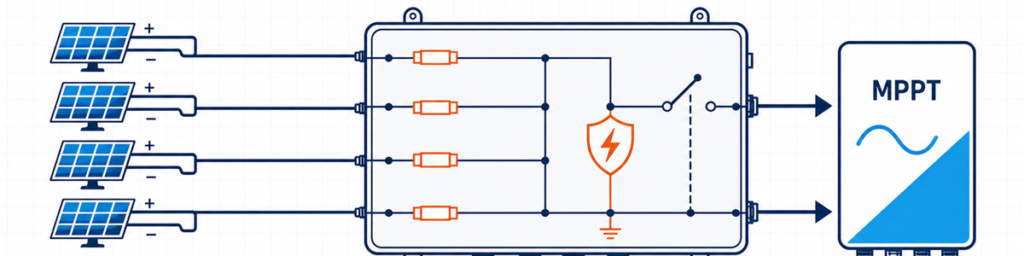
أربع سلاسل PV متصلة عبر صندوق دمج شمسي مزود بصمامات فيوز إلى مدخل MPPT للعاكسيجب أن يتطابق صندوق الدمج الشمسي مع عدد سلاسل PV المتوافقة التي تغذي مدخل عاكس واحد، وأعلى جهد دائرة مفتوحة في الطقس البارد للمصفوفة، والتيار التصميمي المجمّع بناءً على Isc، والحماية المطلوبة في ذلك الموقع. عدد المداخل وحده غير كافٍ. قد تحتاج أربع سلاسل إلى صندوق 4-داخل/1-خارج واحد، أو دائرتين منفصلتين 2-داخل/1-خارج، أو لا تحتاج إلى صندوق دمج خارجي على الإطلاق، حسب العاكس وتخطيط الكابلات.
بالنسبة للمشتري، "4 سلاسل، 1000 فولت" تبدو كمواصفة قابلة للاستخدام. بالنسبة للمهندس الذي يراجع العرض، هذا مجرد البداية. قد تُظهر ورقة بيانات الوحدة أن السلسلة تقترب من 1000 فولت في صباح بارد. قد يخصص العاكس السلاسل إلى MPPTs مستقلة. قد يحتاج مسار الخرج إلى حمل ما يقرب من 70 A بعد تطبيق عامل التيار للمشروع. أي من هذه الحقائق يمكن أن يغير الصندوق.
الهدف هنا هو تحويل المعلومات الموجودة بالفعل في ورقة بيانات الوحدة، وجدول العاكس، ومخطط الخط الواحد إلى مواصفة أولية قابلة للدفاع عنها. للتكوينات العامة والخيارات المتاحة للمنتجات، انظر نطاق صناديق الدمج PV من JUTRION.
ابدأ برسم العاكس، وليس عدد السلاسل على السطح
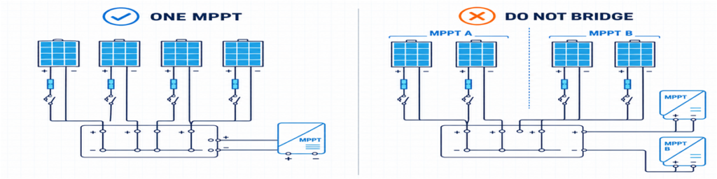
تجميع صحيح لسلاسل PV لمسار MPPT واحد مقارنة بالربط غير الصحيح بين مدخلات MPPT منفصلةيجب أن يكون للسلاسل التي تدخل مخرج صندوق تجميع واحد وجهة صالحة. يبدو ذلك واضحًا، ومع ذلك فهو المكان الذي تخطئ فيه العديد من العروض المبكرة.
لنفترض أن سطحًا يحتوي على ثماني سلاسل. يخصص رسم العاكس أربعًا إلى MPPT A وأربعًا إلى MPPT B. طلب صندوق تجميع 8-مداخل/1-مخرج سيربط دائرتين صمم العاكس للتحكم فيهما بشكل مستقل. الخيارات العملية عادةً هي مجموعتان منفصلتان 4-مداخل/1-مخرج، أو حاوية واحدة تحتوي على قسمين مستقلين كهربائيًا، أو توصيلات سلاسل مباشرة إذا كان العاكس يوفر بالفعل مدخلات وحماية مناسبة.
يجب أيضًا أن تكون السلاسل المخصصة للعمل بالتوازي متوافقة حقًا. تحقق من نوع الوحدة، وعدد الوحدات لكل سلسلة، والاتجاه، والتظليل المتوقع. أطوال السلاسل غير المتساوية لها جهود تشغيل مختلفة. يمكن أن يؤدي دمج سلاسل مظللة بشدة وغير مظللة إلى تطابق تشغيل ضعيف حتى عندما تكون ملصقات الوحدات متطابقة.
هذا يعطي القاعدة الأولى القابلة للاستخدام:
احسب السلاسل المخصصة لمسار MPPT واحد متوافق، وليس كل سلسلة ظاهرة في رسم المشروع.
عندما يضيف صندوق التجميع الخارجي قيمة قليلة
توفر العديد من العاكسات السلسلية بالفعل مدخلات DC متعددة، وحماية داخلية من الصواعق، ووظيفة عزل DC. إذا كانت كل سلسلة يمكن أن تعمل مباشرة إلى مدخل عاكس مناسب، فإن إضافة صندوق تجميع خارجي قد يخلق توصيلات كابلات إضافية دون حل مشكلة تصميمية.
صندوق السلسلة الواحدة هو حالة مختلفة لكنها ذات صلة. وحدة 1-مدخل/1-مخرج لا تجمع التيار؛ إنها تعمل كصندوق حماية وعزل خارجي. يمكن أن يكون ذلك مفيدًا حيث يكون العاكس بعيدًا، أو تكون نقطة عزل محلية مطلوبة، أو يريد المشروع حماية قابلة للاستبدال من الصواعق في موقع يسهل الوصول إليه.
الأرقام الخمسة التي تستحق وضعها على ورقة واحدة
قبل النظر إلى أحجام الفيوزات أو أبعاد الحاوية، اجمع خمس مجموعات من المعلومات. يمكن نسخ معظمها مباشرة من مستندات المشروع الصادرة.
| المعلومات | من أين تأتي عادةً | ما الذي تغيره |
|---|---|---|
| Voc، Isc، Imp، معامل درجة الحرارة، والفيوز الأقصى للسلسلة | ورقة بيانات وحدة PV | حدود الجهد والتيار وفيوز السلسلة |
| عدد الوحدات لكل سلسلة وعدد السلاسل المتوازية | جدول السلاسل | عدد المدخلات والجهد/التيار الإجمالي |
| ترتيب MPPT وحدود المدخلات | ورقة بيانات العاكس ومخطط الخط الواحد | أي السلاسل قد تشارك في مخرج واحد |
| درجة الحرارة الدنيا، التركيب، والتعرض | أساس تصميم المشروع وبيانات الموقع | Voc البارد، خفض التصنيف، والحاوية |
| البلد الوجهة والقواعد المعمول بها | مواصفة المشروع | طريقة الحماية والتوثيق |
قيمة واحدة غالبًا ما تُغفل هي الحد الأقصى المسموح به لتيار القصر للعاكس. الحد الأقصى لتيار التشغيل والحد الأقصى لتيار القصر ليسا قابلين للتبادل. يجب فحص المصفوفة المقترحة مقابل كليهما.
البلد الوجهة مهم بقدر البيانات الكهربائية. حساب الفيوز المُعد لمشروع موجه نحو IEC لا ينبغي أن يستعير بهدوء مضاعفًا لأمريكا الشمالية ويقدمه كقاعدة عالمية.
تحقق من جهد السلسلة البارد قبل اختيار 1000 فولت أو 1500 فولت
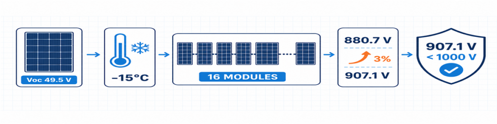
حساب جهد دائرة مفتوحة لسلسلة PV في الطقس البارد لـ 16 وحدة ينتج عنه جهد تصميم 907.1 فولتيتم ذكر Voc للوحدة عادةً في ظروف الاختبار القياسية. يرتفع مع انخفاض درجة حرارة الخلية، لذا فإن أبرد حالة متوقعة تتحكم في أقصى جهد للسلسلة.
حيث تعطي ورقة بيانات الوحدة معامل درجة حرارة سالب لـ Voc كنسبة مئوية لكل درجة مئوية، يكون الحساب الأولي:
Voc،بارد = Voc،STC × [1 + |βVoc| × (25 − Tدقيقة)]
Vسلسلة، بارد = Voc،بارد × عدد الوحدات في السلسلة
أدخل المعامل كرقم عشري. على سبيل المثال، −0.28%/°C يصبح 0.0028 في الصيغة. إذا قدمت الشركة المصنعة للوحدة طريقة مختلفة لدرجات الحرارة المنخفضة، استخدم تلك الطريقة بدلاً من ذلك.
يجب أن يتناسب الحل مع أكثر من العاكس. رابط الصمامات وحاملها، SPD، مفتاح الفصل أو القاطع، الأطراف، الموصلات والتجميع الكامل كلها تقع في نفس دائرة DC. استبدال SPD فقط بجهاز 1500 فولت لا يحول صندوق 1000 فولت إلى تجميع 1500 فولت.
هامش الجهد غير المستخدم القليل ليس قدرة مهدرة. إنه يمتص أساس درجة الحرارة الخاص بالمشروع والتفاوتات التي تم تحديدها فعليًا. ما يجب تجنبه هو هامش عشوائي بدون مصدر موثق.
صمامات السلسلة تعتمد على التيار العكسي، وليس على العادة
عندما تكون السلاسل المتوازية سليمة، تساهم كل منها بالتيار في المخرج المشترك. إذا تعطلت سلسلة واحدة، فقد تغذيها السلاسل الأخرى بالتيار مرة أخرى. صمام السلسلة موجود لقطع هذا التيار العكسي الضار حيث تكون الحماية مطلوبة.
فحص أولي للمساهمة من السلاسل الأخرى هو:
Iعكسي، فحص = (n − 1) × Isc، سلسلة
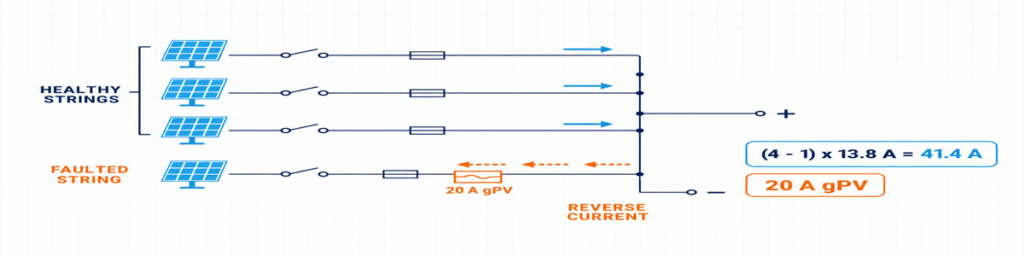
تيار عكسي من ثلاث سلاسل PV سليمة إلى سلسلة معطوبة محمية بفيوز gPV بقيمة 20 Aهنا، n هو عدد السلاسل المتوازية. يوضح التعبير لماذا يتغير الجواب بسرعة بين مدخلين وأربعة: سلسلة معطوبة في مجموعة من أربع سلاسل قد تستقبل تيارًا من ثلاث سلاسل سليمة.
لا تعامل هذا التعبير على أنه تصميم الحماية النهائي. يجب أن يتحمل الفيوز gPV المختار التيار المتوقع تحت ظروف الحاوية الفعلية، ويحمي الكابل والمعدات، ويظل ضمن تصنيف الفيوز التسلسلي الأقصى للوحدة، وأن يكون لديه جهد تيار مستمر PV وقدرة قطع مناسبة. يتم فحص الحامل والفيوز معًا، بما في ذلك تأثيرات درجة الحرارة والتجميع.
IEC 60269-6 يغطي المتطلبات التكميلية لروابط الفيوز المستخدمة في سلاسل ومصفوفات الطاقة الكهروضوئية حتى 1500 فولت تيار مستمر. تحدد قواعد التركيب المعتمدة للمشروع كيفية تطبيق هذا المنتج.
حول الرقم 1.56 × Isc الذي يُرى على الإنترنت
الرقم المألوف 1.56 × Isc مرتبط بعاملين 125% المستخدمين في مسارات التصميم الشائعة في أمريكا الشمالية. لا ينبغي إعادة تسميته كصيغة IEC عالمية. إذا كان المشروع محكومًا بـ NEC، استخدم الإصدار المعتمد وقوائم المعدات والمتطلبات المحلية. إذا كان مشروع IEC، طبق قواعد التركيب ذات الصلة المستندة إلى IEC وتعليمات الشركات المصنعة للوحدة والصمام والكابل.
هذا التمييز يستحق الذكر في عرض السعر. وإلا، قد يعيد موردان أحجام صمامات مختلفة حتى لو تلقيا نفس بيانات المصفوفة.
قم بحساب المسار المدمج بشكل منفصل عن كل مدخل
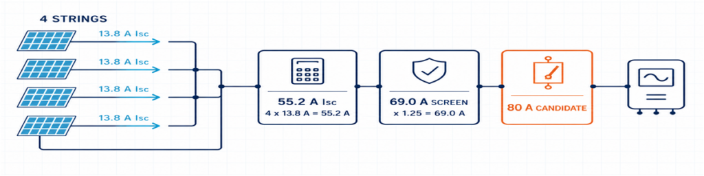
أربع سلاسل PV بقوة 13.8 A مجتمعة إلى 55.2 A Isc مع تيار تصميم 69 A وجهاز إخراج مرشح بقيمة 80 Aجانبا الإدخال والإخراج يحملان تيارات مختلفة. كل مدخل يحمل سلسلة واحدة؛ المخرج المشترك يحمل مجموع السلاسل المتوازية.
Isc، إجمالي = عدد السلاسل المتوازية × Isc، سلسلة
يتم بعد ذلك تطبيق عامل التصميم المطلوب للمشروع وعوامل التصحيح على الموصلات والمعدات المناسبة. تؤثر النتيجة على الأسلاك الداخلية، والقضبان، والأطراف، والكابل الخارجي، وجهاز التبديل للإخراج. كما يجب مقارنتها بالحدود المعلنة للعاكس.
استخدام Imp وحده للاختيار الكامل قد يترك مسار الحماية صغيرًا جدًا. استخدام Isc وحده دون فحص تيار MPPT الطبيعي للعاكس قد يفوت قيدًا تشغيليًا. أبقِ القيم منفصلة وأعطِ كلًا منها غرضًا.
| القيمة | استخدمها للتحقق من |
|---|---|
| سلسلة Imp | تيار التشغيل العادي وتوافق MPPT للعاكس |
| سلسلة Isc | تيار التصميم للسلسلة وحسابات الحماية من التيار الزائد |
| إجمالي Isc | المسار المدمج وحد تيار الدائرة القصيرة للعاكس |
| تيار التصميم المصحح للمشروع | الموصلات، والقضبان، والأطراف، وجهاز الإخراج تحت الظروف المركبة |
يمكن للحرارة أن تتجاوز تصنيف الكتالوج الذي يبدو مريحًا. تؤدي حوامل الفيوز المتجمعة عن كثب، وخسائر الأطراف، وSPD، والإشعاع الشمسي المباشر جميعها إلى زيادة درجة حرارة الحاوية. جهاز 80 A في حالة مرجعية ليس بالضرورة أن يكون حل 80 A داخل كل صندوق خارجي.
الصمامات، والعزل، والقواطع، ومانعات الصواعق لها وظائف مختلفة
صندوق الدمج أسهل في التحديد عندما يكون لكل مكون واجب واحد واضح:
- صمام gPV: يحمي سلسلة فردية ضد حالة التيار العكسي الزائد المطبقة؛;
- مفتاح الفصل: يوفر تبديل حمل بتصنيف تيار مستمر PV ونقطة عزل محددة؛
- قاطع دائرة التيار المستمر: يقوم بتبديل الدائرة ويوفر وظيفة الحماية من التيار الزائد عندما تتناسب خصائصه وتصنيفات القطع للتيار المستمر مع التطبيق؛
- SPD تيار مستمر PV: يحد من الجهد الزائد العابر ولا يحل محل الحماية من التيار الزائد أو العزل.
قاطع الإخراج ليس إلزاميًا ببساطة لوجود مساحة له. قد يتطلب تصميم النظام مفتاح فصل حيث تكون الحماية من التيار الزائد مقدمة بالفعل في مكان آخر، أو قاطعًا بواجب حماية محدد. حدد الوظيفة أولاً.
ينطبق نفس المبدأ على جهاز الحماية من الصواعق (SPD). تأكد من تطبيق PV DC، Uمرض الجدري, ، أوضاع الحماية، مستوى الحماية، واجب تيار التفريغ، سلوك الدائرة القصيرة، والتنسيق الاحتياطي. النوع 2 يُستخدم عادةً لظروف الجهد المستحث. حيث يوجد نظام حماية خارجي من الصواعق أو مسار تيار صاعق آخر، قد يتطلب الترتيب حماية من النوع 1 أو النوع 1+2. انظر نطاق JUTRION PV DC SPD بعد معرفة جهد المشروع وسياق الصواعق.
بالنسبة لوظيفة العزل، فإن الجهاز المصنف لواجب PV المقصود أكثر معنى من وصف “مفتاح DC” عام. نطاق JUTRION PV DC isolator يتضمن خيارات DC-PV2 للمراجعة مقابل الجهد والتيار وترتيب الأقطاب المطلوبة.
مثال بأربع سلاسل من ورقة البيانات إلى الصندوق
مثال توضيحي: هذه حالة سقف تجاري مُنشأة تُستخدم لإظهار الحساب. إنها ليست مشروع عميل أو تصميمًا عامًا.
تم تخصيص أربع سلاسل متطابقة إلى مدخل عاكس تيار عالي. تحتوي كل سلسلة على 16 وحدة. تعطي ورقة بيانات الوحدة Voc = 49.5 فولت، Isc = 13.8 أمبير، βVoc = −0.28%/°C وتصنيف فيوز تسلسلي أقصى 25 أمبير. درجة الحرارة الدنيا للمشروع هي −15°C. كما يطبق أساس التصميم سماحًا بنسبة 3% بعد حساب درجة الحرارة.
العاكس التوضيحي له مدخل تيار مستمر بحد أقصى 1000 فولت، تيار إدخال أقصى 80 أمبير، وتيار قصر أقصى 100 أمبير. لا يُفترض وجود نظام حماية من الصواعق خارجي.
الرسم يشير إلى أربعة مدخلات ومخرج واحد
تستخدم جميع السلاسل الأربع نفس الوحدات وطول السلسلة، وتسمح وثائق العاكس لها بتغذية نفس المدخل. بنية 4-مدخل/1-مخرج مناسبة إذن في هذه المرحلة. إذا قسم الرسم بين مساري MPPT، فستصبح الإجابة مجموعتين مستقلتين 2-مدخل/1-مخرج.
تصل السلسلة الباردة إلى 907.1 فولت
Voc للوحدة الباردة = 49.5 × [1 + 0.0028 × (25 − (−15))] = 55.04 فولت
Voc للسلسلة الباردة = 55.04 × 16 = 880.7 فولت
جهد تصميم المشروع = 880.7 × 1.03 = 907.1 فولت
يمكن لتجميع 1000 فولت موثق أن يجتاز هذا الفحص الأولي، وكذلك العاكس التوضيحي. الهامش المتبقي حوالي 93 فولت. الوحدة السابعة عشر سترفع النتيجة إلى حوالي 964 فولت قبل السماح نفسه ولن تجتاز هذا المثال بعد تطبيق السماح.
السلاسل المتوازية تجعل الصمامات الفردية ضرورية
يمكن للسلاسل الثلاث الأخرى المساهمة بفحص أولي للتيار العكسي:
(4 − 1) × 13.8 = 41.4 أمبير
هذا أعلى من تصنيف الفيوز التسلسلي الأقصى للوحدة البالغ 25 أمبير، لذا يلزم حماية سلسلة فردية في هذا المثال. تنتج طريقة المشروع شاشة تيار فيوز أولية دنيا بقيمة 1.25 × 13.8 = 17.25 أمبير. يقع فيوز gPV بقوة 20 أمبير بين هذه القيمة وحد 25 أمبير للوحدة. قبل قبوله، يجب فحص الحامل، حماية الكابل، درجة حرارة الحاوية، وقدرة التيار المستمر.
المخرج المشترك يحتاج إلى أكثر من تصنيف 55.2 أمبير
تيار الدائرة القصيرة المجمع هو:
4 × 13.8 = 55.2 أمبير
يستخدم أساس تصميم المثال 1.25 × Isc كفحص أولي لتيار المخرج:
1.25 × 55.2 = 69.0 أمبير
مفتاح فصل تيار مستمر PV بقوة 80 أمبير هو إطار بداية معقول، وليس اختيارًا نهائيًا تلقائيًا. يجب التحقق من التصنيف الحراري المثبت، الجهد، الأقطاب وعبء التبديل. يمر حد قصر العاكس 100 أمبير مقارنة 55.2 أمبير. يجب مقارنة حد التشغيل 80 أمبير بأربعة أضعاف Imp للوحدة من ورقة البيانات الحقيقية.
الصندوق الأولي الآن محدد بما فيه الكفاية للمراجعة: أربعة مداخل، لكل منها مصهر مستقل، مخرج واحد مشترك، مكونات فئة 1000 فولت في كل مكان، مسار مشترك مصمم حول قيمة 69 أمبير المذكورة للتحقق الأولي، عزل تيار مستمر PV وSPD تيار مستمر PV من النوع 2 خاضع للتنسيق النهائي.
النتيجة في صفحة واحدة
يصبح الحساب أسهل للمراجعة عندما تبقى الافتراضات والنتيجة والفحص المتبقي معًا. هذه أيضًا هي النقطة التي يمكن للمشتري أن يرى فيها ما إذا كان عرضا الأسعار مبنيين فعليًا على نفس المتطلبات.
| عنصر الاختيار | النتيجة التوضيحية | ما الذي لا يزال بحاجة إلى تأكيد |
|---|---|---|
| التكوين | 4 مدخلات / 1 مخرج | جميع السلاسل الأربع تغذي مدخل عاكس واحد متوافق |
| أقصى جهد للمشروع | 907.1 فولت | أساس درجة حرارة الموقع، طريقة التسامح، وحد العاكس |
| حماية السلسلة | اختيار أولي لفيوز gPV بقوة 20 أمبير | درجة حرارة حامل الفيوز، حماية الكابل والقواعد المعمول بها |
| تيار القصر المشترك | 55.2 A | أقصى تيار قصر مسموح به للعاكس |
| شاشة التيار الإخراجي الأولية | 69.0 A | عوامل التصحيح ودرجة حرارة التجميع المثبتة |
| عزل الإخراج | إطار 80 أمبير هو مرشح بداية | عبء تيار مستمر PV، الجهد، الأقطاب وتصنيف التيار المثبت |
| حماية من الارتفاعات المفاجئة | SPD تيار مستمر PV من النوع 2 مبدئيًا | Ucpv، أوضاع الحماية، LPS والتنسيق الاحتياطي |
| الهيكل | الحد الأدنى IP65 للخارجية | الأشعة فوق البنفسجية، التآكل، الحرارة، الغدد والتكثف |
الاختيار بين تكوين 1/1، 2/1 و4/1
تعرض JUTRION حالياً منتجات 1000 V DC، IP65 بتكوينات 1-in/1-out، 2-in/1-out و4-in/1-out. استخدم عدد المدخلات لتضييق الخيارات المعمارية، ثم أكد التصنيفات التي أنتجها حساب المشروع.
| التكوين | السبب النموذجي لتضييق الخيارات | السبب للتوقف وإعادة النظر |
|---|---|---|
| 1 مدخل / 1 مخرج | سلسلة واحدة تحتاج إلى نقطة حماية وعزل يمكن الوصول إليها | لا يحدث دمج؛ تحقق من أن صندوقاً منفصلاً يضيف وظيفة مطلوبة |
| 2 مدخلات / 1 مخرج | سلسلتان متطابقتان تغذيان مدخل واحد للعاكس | السلاسل تنتمي إلى MPPTs منفصلة أو تتجاوز حدود المدخلات المجمعة |
| 4 مدخلات / 1 مخرج | أربع سلاسل متطابقة تغذي مدخلاً عالي التيار مصنفاً بشكل مناسب | يحتاج العاكس إلى مجموعتين MPPT أو أن مسار المخرج أقل تصنيفاً |
يشير المثال العملي إلى بنية JUPV1000-4/1. لا يعتمد الفيوز الداخلي، جهاز المخرج أو SPD بناءً على اسم الطراز فقط. يجب تحديد تلك الأجزاء وفقاً لجهد المشروع 907.1 فولت، حماية سلسلة gPV المقترحة 20 أمبير، شاشة التيار المجمّع الأولية 69 أمبير وظروف التركيب الخارجية.
تستحق تكوينات السلاسل المخصصة 1500 V أو الأكبر فحصاً جديداً للمكونات والتجميع. لا ينبغي معاملتها كتغيير ملصق لترتيب المخزون 1000 V.
يمكن للغلاف الخارجي أن يغير تصنيف التيار
غالباً ما تكتمل الحسابات الكهربائية في مكتب عند 25°C. قد يقضي الصندوق عمره التشغيلي على سطح حيث الهواء أكثر حرارة، والشمس المباشرة تدفئ الغلاف، وتحمل عدة حوامل فيوز التيار جنباً إلى جنب. يؤثر هذا الاختلاف على أكثر من مجرد الراحة أثناء الصيانة.
يتم إنتاج الحرارة عند الفيوزات، الأطراف، الموصلات، SPD وجهاز المخرج. المكونات المتقاربة تقل فرص تبريدها، بينما يحد الغلاف المحكم من تبادل الهواء. قد يتطلب المكون الذي يحمل التيار المحدد تحت ظروف مرجعية تخفيض تصنيفه في التجميع النهائي. لهذا السبب يظل مفتاح الفصل 80 A في المثال إطاراً مبدئياً حتى يتم فحص الترتيب المثبت.
IP65 مفيد، لكنه يجيب فقط على سؤال حماية الدخول. لا يثبت تلقائياً:
- مقاومة التعرض طويل الأمد للأشعة فوق البنفسجية؛
- أداء مقاومة التآكل بالقرب من الساحل أو في جو صناعي؛
- درجة الحرارة الداخلية المقبولة تحت التيار الكامل والتحميل الشمسي؛
- التحكم في التكثف أثناء التسخين والتبريد اليومي؛
- ملاءمة غدد الكابلات، الأختام والمواد للكابلات المثبتة؛
- أداء العزل على ارتفاعات عالية.
تفاصيل التركيب مهمة أيضاً. دخول الكابلات من أعلى الغلاف الخارجي يخلق مسار مياه مختلف عن الدخول من الأسفل. الغدد ذات الحجم غير المناسب قد تضر الأختام أو تترك دعماً غير كافٍ للكابل. الانحناءات الحادة للكابلات يمكن أن تنقل القوة الميكانيكية إلى حوامل الفيوز والأطراف. يجب مراجعة الغلاف كتركيب مثبت، وليس كصندوق بلاستيكي أو معدني فارغ مع رقم IP.
IEC 61439-2:2020 يغطي معدات التبديل والتحكم الكهربائية حتى 1500 V DC. الصلة هنا عملية: استخدام مكونات مصنفة بشكل فردي لا يلغي الحاجة إلى التحقق من التجميع المكتمل، بما في ذلك ارتفاع درجة الحرارة، الخصائص العازلة، الدوائر الوقائية، الفواصل، التوصيلات والبناء الميكانيكي حسب الاقتضاء.
أرسل معلومات كافية للمورد للتحقق من النتيجة
استفسار فني قصير أكثر فائدة من نموذج شراء طويل. أرفق أوراق بيانات الوحدة والعاكس واذكر:
- عدد السلاسل لكل مخرج وعدد الوحدات لكل سلسلة؛
- جهد الدائرة المفتوحة للوحدة Voc، تيار الدائرة القصيرة Isc، تيار التشغيل Imp، βVoc وأقصى فيوز تسلسلي؛
- أدنى درجة حرارة تصميم وأي سماح جهد؛
- ترتيب MPPT للعاكس وحدود المدخلات؛
- أقصى جهد محسوب والتيار التصميمي المجمّع؛
- وظائف الفيوز المطلوبة، العزل، القاطع وجهاز حماية من زيادة التيار (SPD);
- موقع الحاوية، متطلبات IP، الظروف المحيطة، التعرض للأشعة فوق البنفسجية والتآكل;
- أحجام الكابلات، المراقبة، سوق الوجهة والكمية.
للمشروع التوضيحي، يصبح ذلك: 4 مدخلات/مخرج واحد، أربع سلاسل متطابقة مكونة من 16 وحدة تغذي MPPT واحد، جهد تصميم المشروع المعلن 907.1 V، فيوزات gPV مبدئية 20 A، تيار قصر الدائرة الكلي 55.2 A، شاشة التيار الخارج المبدئية 69 A، عزل التيار المستمر للـ PV، حماية تنسيق من النوع 2 للتيار المستمر PV SPD وحاوية خارجية.
لماذا قد لا تكون عرضان سعريان "4-سلاسل، 1000 فولت، تصنيف IP65" متكافئان
قد يستخدم عرض سعر واحد روابط فيوز gPV وحوامل تم التحقق منها للجهد ودرجة الحرارة المقصودة. قد يذكر آخر فقط تيار فيوز اسمي. قد يوفر صندوق واحد مفتاح فصل تحميل؛ وقد يستخدم آخر جهازًا مخصصًا أساسًا للعزل. قد تختلف أيضًا حالة جهد الحماية Ucpv لجهاز حماية من زيادة التيار (SPD)، أوضاع الحماية، سلوك القصر واستبدالية الجهاز حتى عندما يقول كلا العرضين "جهاز حماية من زيادة التيار (SPD) من النوع 2".
المخرج المشترك هو مصدر آخر للاختلافات الخفية. قارن قدرة التيار المركبة للبارات الناقلة، الموصلات، الأطراف وجهاز المخرج، وليس فقط أكبر رقم أمبير مطبوع في قائمة المواد. تحقق أيضًا من سعة الطرف مقابل الكابل الخارج الفعلي. عرض السعر الأقل فنيًا ليس أرخص إذا تطلب استبدال غدد الكابلات، حاوية أكبر أو إعادة عمل في الموقع.
لذلك، فإن مقارنة مفيدة تقوم بتوحيد العناصر التالية قبل السعر:
- ترتيب الإدخال/الإخراج وتجميع متعقب نقطة القدرة القصوى (MPPT);
- أقصى جهد DC للمسار الكامل;
- فئة فيوز السلسلة، التصنيف وحدود الوحدة;
- التيار المشترك وظروف درجة الحرارة المركبة;
- وظيفة جهاز المخرج والتحميل DC;
- نوع جهاز حماية من زيادة التيار (SPD)، جهد الحماية Ucpv، الأوضاع والتنسيق;
- سعة الأطراف وغدد الكابلات;
- مادة الحاوية ومدى ملاءمتها البيئية.
يجب أن يُقرأ الاختيار النهائي كمسار كهربائي متصل واحد. إذا أكد عرض السعر فقط عدد المدخلات، الجهد الاسمي وتصنيف IP، فإنه لم يجب بعد على سؤال الحجم.
تحقق من الصندوق بعد التركيب
يمكن أن يتعرض التصميم الصحيح للخطر بسبب قطبية معكوسة، نهايات فضفاضة، غدد تالفة أو سلسلة متصلة بالمدخل الخطأ. يجب أن يتبع التشغيل إجراءات المشروع وتعليمات المكونات، مع عزل دائرة التيار المستمر واختبارها بواسطة فنيين مؤهلين.
قبل تشغيل المخرج المشترك، سجل:
- هوية السلسلة، القطبية وجهد الدائرة المفتوحة المقاس;
- ما إذا كانت جهود السلاسل المقاسة متسقة بشكل معقول مع التصميم ومع بعضها البعض;
- إحكام الأطراف وفقًا لعزم التثبيت المحدد;
- استمرارية الموصل الحامي واستمرارية التأريض حيثما يلزم;
- نوع الفيوز وتصنيفه في كل مسار مشغول;
- مؤشر حالة جهاز حماية من زيادة التيار (SPD) وجهة إنذار عن بعد، إذا تم تركيبه;
- تشغيل ومؤشر وضع جهاز العزل;
- الملصقات، أختام المداخل غير المستخدمة، ضغط غدد الكابلات وإغلاق الحاوية.
بعد تشغيل النظام تحت حمل تمثيلي، افحص وجود تسخين غير طبيعي، تغير اللون، رائحة، تشغيل فيوز غير مبرر أو رطوبة. حيث تستخدم خطة صيانة المشروع التصوير الحراري، تكون الصورة الأساسية أكثر فائدة عندما يتم تسجيل الحمل والظروف المحيطة معها. الهدف ليس "إثبات" التصميم من مسح واحد، بل ترك مرجع للمقارنة لاحقًا.
IEC 62548-1:2023 يوفر السياق الأوسع لتصميم IEC لمصفوفات PV، بما في ذلك الأسلاك DC، الحماية، التبديل والتأريض. كما يحتاج التجميع المكتمل إلى التحقق المناسب; IEC 61439-2:2020 يغطي مجموعات مفاتيح الطاقة وأجهزة التحكم حتى 1500 V DC. يتم معالجة متطلبات SPD DC PV بواسطة IEC 61643-31.
لمقارنة النتيجة مع تكوين JUTRION، أرسل جدول السلاسل، بيانات الوحدة والعاكس، درجة حرارة الموقع، متطلبات الحماية والمعيار الوجهة عبر صفحة صندوق الدمج PV. هذا يمنح كلا الطرفين شيئًا أكثر موثوقية للنقاش من "أربع سلاسل، أفضل سعر."
الأسئلة الشائعة
كم عدد سلاسل الطاقة الشمسية التي تتطلب صندوق دمج؟
لا يوجد حد أدنى عالمي. يكون المجمع الخارجي مفيدًا عندما تحتاج السلاسل المتوافقة إلى التوازي قبل مدخل واحد للعاكس، أو عندما يقلل من طول مسارات الكابلات، أو عندما يحتاج المشروع إلى موقع مركزي للصمامات، العزل، الحماية من الارتفاعات المفاجئة أو المراقبة. إذا كان العاكس يقبل بالفعل كل سلسلة مباشرة ويوفر الوظائف المطلوبة، فقد لا يكون المجمع المنفصل ضروريًا.
ما مقاس المصهر الذي يجب استخدامه في صندوق تجميع الطاقة الشمسية؟
اختر صمام gPV مصنف للطاقة الشمسية بناءً على تيار الدائرة القصيرة للسلسلة Isc، وطريقة التركيب المطبقة، وسعة الكابل، والظروف البيئية، وأقصى تصنيف للصمام التسلسلي للوحدة. يجب أن يحمل الصمام التيار المتوقع دون تشغيل خاطئ مع البقاء منخفضًا بما يكفي لحماية الوحدة والكابل. لا تطبق 1.56 × Isc كقاعدة IEC عامة؛ فالحساب يعتمد على المعيار الوجهة.
هل يمكن للسلاسل المتصلة بمتعقبات MPPT مختلفة أن تشترك في صندوق تجميع واحد؟
يمكنها مشاركة الغلاف الفيزيائي فقط إذا ظلت دوائر MPPT منفصلة كهربائيًا. لا تدمج مخرجات مجموعات MPPT المستقلة ما لم يسمح مصنع العاكس صراحةً بهذا التصميم. يجب أن يكون لكل مجموعة سلاسل متوافقة خاصة بها، ومسار إخراج، وتصنيفات خاصة بها.
هل أحتاج إلى صندوق تجميع PV بجهد 1000 فولت أم 1500 فولت؟
احسب أقصى جهد دائرة مفتوحة في الطقس البارد للسلسلة الكاملة وضمن المخصصات المطلوبة بطريقة المشروع. اختر فئة جهد تحافظ على العاكس وكل مكون في مسار المجمع ضمن التصنيف. وجود SPD بجهد 1500 فولت فقط لا يجعل الصندوق المكتمل مناسبًا لجهد 1500 فولت.
ما الفرق بين صندوق تجميع PV وصندوق حماية PV؟
صندوق تجميع PV يدمج مدخلين أو أكثر من السلاسل المتوافقة إلى مخرج مشترك. صندوق حماية PV بمدخل واحد ومخرج واحد لا يجمع السلاسل؛ بل يوفر موقعًا مناسبًا لوظائف مثل العزل، الحماية من الارتفاعات المفاجئة أو الحماية من التيار الزائد على دائرة سلسلة واحدة.
المراجع الفنية
