

Réponse rapide : Quelle taille de coffret de regroupement solaire vous faut-il ?
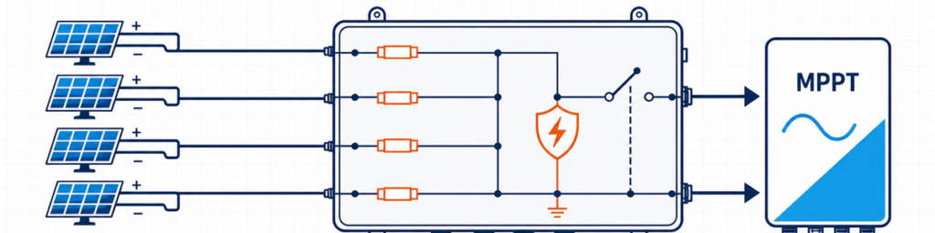
Quatre chaînes photovoltaïques reliées via un coffret de regroupement solaire à fusibles à une entrée MPPT de l’onduleurA solar combiner box should match the number of compatible PV strings feeding one inverter input, the array’s highest cold-weather open-circuit voltage, the combined Isc-based design current, and the protection required at that location. Input count alone is not enough. Four strings may need one 4-in/1-out box, two separate 2-in/1-out circuits, or no external combiner at all, depending on the inverter and cable layout.
For a buyer, “4 strings, 1000 V” sounds like a usable specification. For the engineer checking the quotation, it is only the beginning. The module datasheet may show that the string approaches 1000 V on a cold morning. The inverter may assign the strings to two independent MPPTs. The output path may need to carry nearly 70 A after the project’s current factor is applied. Any one of those facts can change the box.
L’objectif ici est de transformer les informations déjà présentes sur la fiche technique du module, le planning des onduleurs et le schéma unifilaire en une spécification préliminaire défendable. Pour les configurations générales et les options de produits disponibles, voir la gamme de coffrets de regroupement photovoltaïques JUTRION.
Commencez par le schéma de l’onduleur, pas par le nombre de chaînes sur le toit
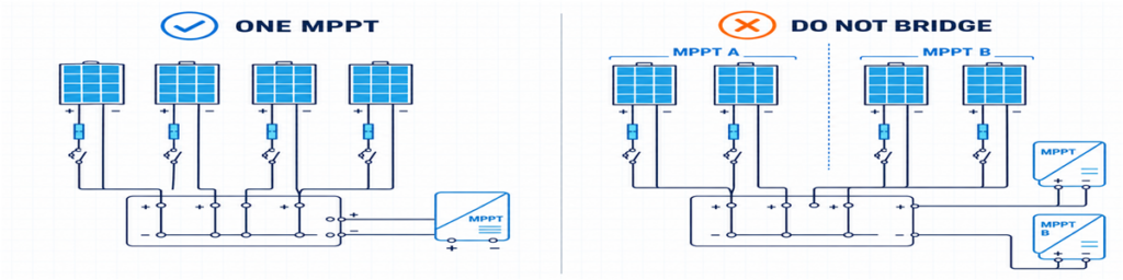
Regroupement correct des chaînes photovoltaïques pour un MPPT, comparé au pontage incorrect d’entrées MPPT séparéesLes chaînes entrant dans une sortie de regroupement doivent avoir une destination valide. Cela semble évident, et pourtant c’est là que de nombreux devis précoces se trompent.
Supposons qu’un toit comporte huit chaînes. Le schéma de l’onduleur en affecte quatre au MPPT A et quatre au MPPT B. Demander un coffret de regroupement 8 entrées/1 sortie reviendrait à relier deux circuits que l’onduleur a été conçu pour commander indépendamment. Les choix réalisables sont normalement deux groupes séparés 4 entrées/1 sortie, une enveloppe contenant deux sections électriquement indépendantes, ou des connexions directes des chaînes si l’onduleur fournit déjà des entrées et une protection adaptées.
Les chaînes destinées à fonctionner en parallèle doivent aussi être réellement compatibles. Vérifiez le type de module, le nombre de modules par chaîne, l’orientation et l’ombrage attendu. Des longueurs de chaînes inégales ont des tensions de fonctionnement différentes. Combiner des chaînes fortement ombragées et non ombragées peut aussi produire un mauvais appariement de fonctionnement même lorsque les étiquettes des modules sont identiques.
Cela donne la première règle utilisable :
Comptez les chaînes affectées à un chemin MPPT compatible, pas toutes les chaînes visibles sur le plan du projet.
Quand un coffret de regroupement externe apporte peu de valeur
De nombreux onduleurs string fournissent déjà plusieurs entrées CC, une protection interne contre les surtensions et une fonction de sectionnement CC. Si chaque chaîne peut être câblée directement vers une entrée d’onduleur adaptée, l’ajout d’un coffret de regroupement externe peut créer des terminaisons de câbles supplémentaires sans résoudre un problème de conception.
Un coffret à une seule chaîne est un cas lié mais différent. Une unité 1 entrée/1 sortie ne regroupe pas le courant ; elle agit comme un coffret externe de protection et de sectionnement. Cela peut être utile lorsque l’onduleur est éloigné, qu’un point de sectionnement local est requis, ou que le projet souhaite une protection contre les surtensions remplaçable dans un emplacement accessible.
Les cinq chiffres qu’il vaut la peine de mettre sur une seule feuille
Avant de regarder les calibres des fusibles ou les dimensions de l’enveloppe, rassemblez cinq groupes d’informations. La plupart peuvent être copiés directement à partir des documents de projet émis.
| Informations | D’où elle provient normalement | Ce qu’elle modifie |
|---|---|---|
| Voc, Isc, Imp, coefficient de température et fusible série maximal | Fiche technique du module photovoltaïque | Limites de tension, de courant et de fusible de chaîne |
| Modules par chaîne et nombre de chaînes en parallèle | Tableau des chaînes | Nombre d’entrées et tension/courant totaux |
| Configuration MPPT et limites d’entrée | Fiche technique de l’onduleur et schéma unifilaire | Quelles chaînes peuvent partager une sortie |
| Température minimale, montage et exposition | Base de conception du projet et données du site | Voc à froid, déclassement et coffret |
| Pays de destination et règles applicables | Spécification du projet | Méthode de protection et documentation |
One value that often gets missed is the inverter’s maximum permissible short-circuit current. The maximum operating current and maximum short-circuit current are not interchangeable. A proposed array should be checked against both.
Le pays de destination compte tout autant que les données électriques. Un calcul de fusible préparé pour un projet orienté CEI ne devrait pas emprunter discrètement un multiplicateur nord-américain et le présenter comme une règle universelle.
Vérifiez la tension de chaîne à froid avant de choisir 1000 V ou 1500 V
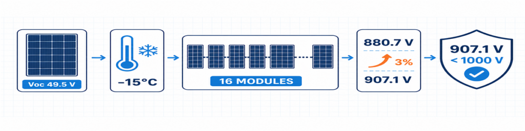
Calcul de la Voc d’une chaîne photovoltaïque par temps froid pour 16 modules aboutissant à une tension de conception de 907,1 VLa Voc du module est normalement indiquée aux conditions d’essai standard. Elle augmente lorsque la température des cellules baisse, donc la condition la plus froide attendue détermine la tension maximale de la chaîne.
Lorsque la fiche technique du module donne un coefficient de température Voc négatif en pourcentage par degré Celsius, un calcul initial est :
Voc,froid = Vco,STC × [1 + |βVoc| × (25 − Tmin)]
Vstring,cold = Voc,froid × nombre de modules en série
Saisissez le coefficient sous forme décimale. Par exemple, −0,28%/°C devient 0,0028 dans la formule. Si le fabricant du module fournit une méthode basse température différente, utilisez plutôt cette méthode.
La réponse doit convenir à plus que l’onduleur. Le fusible et son porte-fusible, le parafoudre, l’interrupteur-sectionneur ou le disjoncteur, les bornes, les conducteurs et l’ensemble complet se trouvent tous dans le même circuit CC. Remplacer uniquement le parafoudre par un dispositif 1500 V ne transforme pas un coffret 1000 V en ensemble 1500 V.
Une petite marge de tension inutilisée n’est pas une capacité gaspillée. Elle absorbe la base de température propre au projet et les tolérances qui ont réellement été identifiées. Ce qu’il faut éviter, c’est une marge aléatoire sans source documentée.
Les fusibles de chaîne dépendent du courant inverse, pas de l’habitude
Lorsque les chaînes en parallèle sont saines, chacune contribue au courant de sortie commun. Si une chaîne développe un défaut, les autres peuvent y renvoyer du courant. Le fusible de chaîne est là pour interrompre ce courant inverse dommageable lorsqu’une protection est requise.
Un premier filtre pour la contribution des autres chaînes est :
Iinverse,screen = (n − 1) × Isc,string
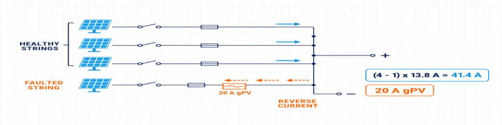
Courant inverse de trois chaînes PV saines vers une chaîne en défaut protégée par un fusible gPV de 20 AIci, n est le nombre de chaînes en parallèle. L’expression montre pourquoi la réponse change rapidement entre deux et quatre entrées : une chaîne en défaut dans un groupe de quatre chaînes peut recevoir le courant de trois chaînes saines.
Do not treat that expression as the finished protection design. The selected gPV fuse must carry expected current under the actual enclosure conditions, protect the cable and equipment, stay within the module’s maximum series-fuse rating, and have adequate PV DC voltage and breaking capability. The holder and fuse are checked together, including temperature and grouping effects.
IEC 60269-6 couvre les exigences complémentaires pour les fusibles utilisés dans les chaînes et les champs photovoltaïques jusqu’à 1500 V CC. Les règles d’installation adoptées pour le projet déterminent la manière dont ce produit est appliqué.
À propos du chiffre 1,56 × Isc vu en ligne
The familiar 1.56 × Isc figure is associated with two 125% factors used in common North American design paths. It should not be relabelled as a universal IEC formula. If the project is governed by the NEC, use the adopted edition, equipment listings and local requirements. If it is an IEC project, apply the relevant IEC-based installation rules and the module, fuse and cable manufacturers’ instructions.
Cette distinction mérite d’être précisée dans le devis. Sinon, deux fournisseurs peuvent proposer des calibres de fusibles différents alors qu’ils ont reçu les mêmes données de champ.
Dimensionnez le chemin combiné séparément de chaque entrée
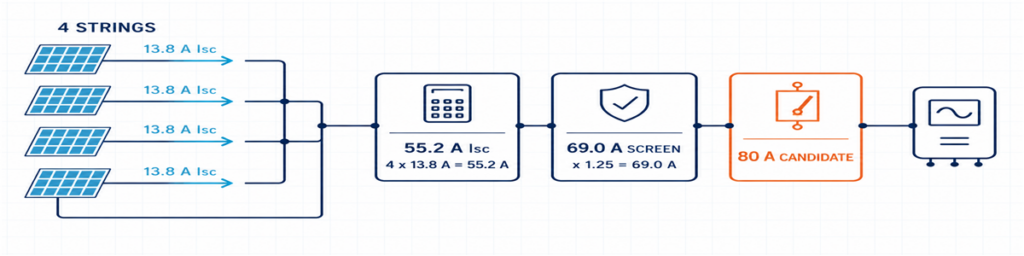
Quatre chaînes PV de 13,8 A combinées à 55,2 A Isc avec un filtre de conception de 69 A et un dispositif de sortie candidat de 80 ALes côtés entrée et sortie transportent des courants différents. Chaque entrée transporte une chaîne ; la sortie commune transporte la somme des chaînes en parallèle.
Isc,total = nombre de chaînes en parallèle × Isc,string
The project’s required design factor and correction factors are then applied to the appropriate conductors and equipment. The result affects internal wiring, busbars, terminals, the outgoing cable and the output switching device. It also needs to be compared with the inverter’s stated limits.
Using Imp alone for the entire selection can leave the protection path too small. Using Isc alone without checking the inverter’s normal MPPT current can miss an operating limitation. Keep the values separate and give each one a purpose.
| Valeur | Utilisez-la pour vérifier |
|---|---|
| Imp de chaîne | Courant de fonctionnement normal et compatibilité MPPT de l’onduleur |
| Isc de chaîne | Courant de dimensionnement de chaîne et calculs de protection contre les surintensités |
| Isc total | Chemin combiné et limite de courant de court-circuit de l’onduleur |
| Courant de dimensionnement corrigé du projet | Conducteurs, jeux de barres, bornes et dispositif de sortie dans les conditions installées |
La chaleur peut l’emporter sur un calibre catalogue apparemment confortable. Des porte-fusibles étroitement groupés, les pertes aux bornes, le parafoudre et le rayonnement solaire direct augmentent tous la température de l’enveloppe. Un dispositif de 80 A en condition de référence n’est pas automatiquement une solution de 80 A dans chaque coffret extérieur.
Fusibles, sectionnement, disjoncteurs et parafoudres ont des rôles différents
Un coffret de regroupement est plus facile à spécifier lorsque chaque composant a une fonction claire :
- fusible gPV : protège une chaîne individuelle contre la condition de courant inverse applicable ;
- sectionneur : assure la commutation de charge en courant continu PV et un point de sectionnement défini ;
- disjoncteur DC : commute le circuit et assure une fonction de surintensité lorsque ses caractéristiques et ses pouvoirs de coupure en courant continu conviennent à l’application ;
- parafoudre DC PV : limite les surtensions transitoires et ne remplace ni la protection contre les surintensités ni le sectionnement.
Un disjoncteur de sortie n’est pas obligatoire simplement parce qu’il y a de la place pour un. La conception du système peut exiger un sectionneur lorsque la protection contre les surintensités est déjà assurée ailleurs, ou un disjoncteur avec une fonction de protection définie. Décidez d’abord de la fonction.
Le même principe s’applique au parafoudre. Confirmez l’application DC PV, UCPV, protection modes, protection level, discharge-current duty, short-circuit behaviour and backup coordination. Type 2 is commonly used for induced surge conditions. Where an external lightning protection system or another lightning-current path is present, the arrangement may need Type 1 or Type 1+2 protection. See the JUTRION PV DC SPD range after the project voltage and lightning context are known.
For the isolating function, a device rated for the intended PV duty is more meaningful than a generic “DC switch” description. The JUTRION PV DC isolator range includes DC-PV2 options for review against the required voltage, current and pole arrangement.
A Four-String Example from Datasheet to Box
Illustrative example: This is a constructed commercial-rooftop case used to show the calculation. It is not a customer project or a universal design.
Four identical strings are assigned to one high-current inverter input. Each string contains 16 modules. The module datasheet gives Voc = 49.5 V, Isc = 13.8 A, βVoc = −0.28%/°C and a maximum series-fuse rating of 25 A. The project minimum temperature is −15°C. Its design basis also applies a stated 3% allowance after the temperature calculation.
The illustrative inverter has a 1000 V maximum DC input, an 80 A maximum input current and a 100 A maximum short-circuit current. No external lightning protection system is assumed.
The Drawing Points to Four Inputs and One Output
All four strings use the same modules and string length, and the inverter documentation permits them to feed the same input. A 4-in/1-out architecture is therefore appropriate at this stage. If the drawing divided them between two MPPTs, the answer would become two independent 2-in/1-out groups.
The Cold String Reaches 907.1 V
Cold module Voc = 49.5 × [1 + 0.0028 × (25 − (−15))] = 55.04 V
Cold string Voc = 55.04 × 16 = 880.7 V
Project design voltage = 880.7 × 1.03 = 907.1 V
A verified 1000 V assembly can pass this preliminary check, as can the illustrative inverter. The remaining margin is about 93 V. A seventeenth module would raise the result to approximately 964 V before the same allowance and would not pass this example after the allowance is applied.
Parallel Strings Make Individual Fusing Necessary
The other three strings can contribute an initial reverse-current screen of:
(4 − 1) × 13.8 = 41.4 A
That is above the module’s 25 A maximum series-fuse rating, so individual string protection is required in this example. The project method produces a preliminary lower fuse-current screen of 1.25 × 13.8 = 17.25 A. A 20 A gPV fuse sits between that value and the 25 A module limit. Before it is accepted, its holder, cable protection, enclosure temperature and continuous-current capability must be checked.
The Common Output Needs More Than a 55.2 A Label
The combined short-circuit current is:
4 × 13.8 = 55.2 A
The example design basis uses 1.25 × Isc as its preliminary output-current screen:
1.25 × 55.2 = 69.0 A
An 80 A PV DC switch-disconnector is a reasonable starting frame, not an automatic final choice. The installed thermal rating, voltage, poles and switching duty remain to be checked. The inverter’s 100 A short-circuit limit passes the 55.2 A comparison. Its 80 A operating limit should be compared with four times the module Imp from the real datasheet.
The preliminary box is now specific enough to review: four independently fused inputs, one combined output, 1000 V-class components throughout, a combined path designed around the stated 69 A screen, PV DC isolation and a Type 2 PV DC SPD subject to final coordination.
The Result on One Page
The calculation is easier to review when the assumptions, result and remaining check are kept together. This is also the point where a buyer can see whether two quotations are actually based on the same duty.
| Selection item | Illustrative result | What still needs confirmation |
|---|---|---|
| Configuration | 4 inputs / 1 output | All four strings feed one compatible inverter input |
| Maximum project voltage | 907.1 V | Site temperature basis, tolerance method and inverter limit |
| String protection | 20 A gPV preliminary selection | Fuse-holder temperature, cable protection and applicable rules |
| Combined short-circuit current | 55.2 A | Inverter maximum permissible short-circuit current |
| Preliminary output-current screen | 69.0 A | Correction factors and installed assembly temperature |
| Output isolation | 80 A frame is a starting candidate | PV DC duty, voltage, poles and installed current rating |
| Surge protection | Type 2 PV DC SPD initially | Ucpv, protection modes, LPS and backup coordination |
| Enclosure | Outdoor IP65 minimum | UV, corrosion, heat, glands and condensation |
Choosing Between a 1/1, 2/1 and 4/1 Configuration
JUTRION currently displays 1000 V DC, IP65 products in 1-in/1-out, 2-in/1-out and 4-in/1-out configurations. Use the input count to shortlist the architecture, then confirm the ratings that the project calculation produced.
| Configuration | Typical reason to shortlist it | Reason to stop and reconsider |
|---|---|---|
| 1 input / 1 output | One string needs an accessible protection and isolation point | No combining occurs; verify that a separate box adds a required function |
| 2 inputs / 1 output | Two matched strings feed one inverter input | The strings belong to separate MPPTs or exceed the combined-input limits |
| 4 inputs / 1 output | Four matched strings feed one suitably rated high-current input | The inverter needs two MPPT groups or the output path is underrated |
The worked example points toward a JUPV1000-4/1 architecture. It does not approve the internal fuse, output device or SPD by model name alone. Those parts have to be quoted against the 907.1 V project voltage, the proposed 20 A gPV string protection, the 69 A preliminary combined-current screen and the outdoor installation conditions.
Custom 1500 V or larger-string configurations deserve a fresh component and assembly check. They should not be treated as a label change to the 1000 V stock arrangement.
The Outdoor Enclosure Can Change the Current Rating
Electrical calculations are often completed in an office at 25°C. The box may spend its working life on a roof where the air is much hotter, direct sunlight warms the enclosure, and several fuse-holders carry current side by side. That difference affects more than comfort during maintenance.
Heat is produced at fuses, terminals, conductors, the SPD and the output device. Closely packed components have less opportunity to cool, while a sealed enclosure restricts air exchange. A component that carries its marked current under its reference conditions may require derating in the final assembly. This is why the 80 A switch-disconnector in the example remains a starting frame until the installed arrangement has been checked.
IP65 is useful, but it answers only an ingress-protection question. It does not automatically establish:
- resistance to long-term ultraviolet exposure;
- corrosion performance near the coast or in an industrial atmosphere;
- acceptable internal temperature under full current and solar loading;
- condensation control during daily heating and cooling;
- suitability of cable glands, seals and materials for the installed cables;
- insulation performance at high altitude.
Mounting details also matter. Cable entries made through the top of an outdoor enclosure create a different water path from bottom entry. Undersized glands may damage seals or leave insufficient cable support. Tight cable bends can transfer mechanical force to fuse-holders and terminals. The enclosure should be reviewed as an installed assembly, not as an empty plastic or metal box with an IP number.
IEC 61439-2:2020 covers power switchgear and controlgear assemblies up to 1500 V DC. The relevance here is practical: using individually rated components does not remove the need to verify the completed assembly, including temperature rise, dielectric properties, protective circuits, clearances, wiring and mechanical construction as applicable.
Send Enough Information for the Supplier to Check the Result
A short technical enquiry is more useful than a long purchasing template. Attach the module and inverter datasheets and state:
- strings per output and modules per string;
- module Voc, Isc, Imp, βVoc and maximum series fuse;
- minimum design temperature and any voltage allowance;
- inverter MPPT arrangement and input limits;
- calculated maximum voltage and combined design current;
- required fuse, isolation, breaker and SPD functions;
- enclosure location, IP requirement, ambient, UV and corrosion exposure;
- cable sizes, monitoring, destination market and quantity.
For the illustrative project, that becomes: 4-in/1-out, four identical 16-module strings feeding one MPPT, 907.1 V stated project design voltage, preliminary 20 A gPV fuses, 55.2 A total Isc, 69 A preliminary output-current screen, PV DC isolation, coordinated Type 2 PV DC surge protection and an outdoor enclosure.
Why Two “4-String, 1000 V, IP65” Quotations May Not Be Equivalent
One quotation may use gPV fuse-links and holders verified for the intended voltage and temperature. Another may list only a nominal fuse current. One box may provide a load-break switch-disconnector; another may use a device intended mainly for isolation. SPD Ucpv, protection modes, short-circuit behaviour and replaceability may also differ even when both quotations say “Type 2 SPD.”
The common output is another source of hidden difference. Compare the installed current capability of the busbars, conductors, terminals and output device, not only the largest ampere number printed in the bill of materials. Also check terminal capacity against the actual outgoing cable. A technically lower-priced quotation is not cheaper if it requires replacement glands, a larger enclosure or rework at site.
A useful comparison therefore normalizes the following items before price:
- input/output arrangement and MPPT grouping;
- maximum DC voltage of the complete path;
- string-fuse class, rating and module limit;
- combined current and installed temperature conditions;
- output device function and DC duty;
- SPD type, Ucpv, modes and coordination;
- terminal and cable-gland capacity;
- enclosure material and environmental suitability.
The final selection should read as one connected electrical path. If the quotation confirms only input count, nominal voltage and IP rating, it has not yet answered the sizing question.
Verify the Box After Installation
A correct design can still be compromised by reversed polarity, loose terminations, damaged glands or a string connected to the wrong input. Commissioning should follow the project procedure and component instructions, with the DC circuit isolated and tested by qualified personnel.
Before energizing the combined output, record:
- string identity, polarity and measured open-circuit voltage;
- whether measured string voltages are reasonably consistent with the design and with one another;
- terminal tightening completed to the specified torque;
- protective-conductor and bonding continuity where required;
- fuse type and rating in every populated way;
- SPD status indication and remote alarm contact, if fitted;
- operation and position indication of the isolating device;
- labels, unused-entry seals, gland compression and enclosure closure.
After the system has operated under representative load, inspect for abnormal heating, discoloration, odour, nuisance fuse operation or moisture. Where the project maintenance plan uses thermography, the baseline image is more useful when load and ambient conditions are recorded with it. The purpose is not to “prove” the design from one scan, but to leave a reference for later comparison.
IEC 62548-1:2023 provides the broader IEC design context for PV arrays, including DC wiring, protection, switching and earthing. The completed assembly also needs appropriate verification; IEC 61439-2:2020 covers power switchgear and controlgear assemblies up to 1500 V DC. PV DC SPD requirements are addressed by IEC 61643-31.
To compare the result with a JUTRION configuration, send the string schedule, module and inverter data, site temperature, protection requirements and destination standard through the PV combiner box page. That gives both sides something more reliable to discuss than “four strings, best price.”
Questions fréquemment posées
How Many Solar Strings Require a Combiner Box?
There is no universal minimum. An external combiner is useful when compatible strings need to be paralleled before one inverter input, when it reduces long cable runs, or when the project needs a centralized location for fuses, isolation, surge protection or monitoring. If an inverter already accepts every string directly and provides the required functions, a separate combiner may not be necessary.
What Size Fuse Should Be Used in a Solar Combiner Box?
Select a PV-rated gPV fuse from the string Isc, applicable installation method, cable capacity, environmental conditions and module maximum series-fuse rating. The fuse must carry expected current without nuisance operation while remaining low enough to protect the module and cable. Do not apply 1.56 × Isc as a universal IEC rule; the calculation depends on the destination standard.
Can Strings Connected to Different MPPTs Share One Combiner Box?
They may share a physical enclosure only if the MPPT circuits remain electrically separate. Do not combine the outputs of independent MPPT groups unless the inverter manufacturer explicitly permits that architecture. Each group should have its own compatible strings, output path and ratings.
Do I Need a 1000V or 1500V PV Combiner Box?
Calculate the maximum cold-weather open-circuit voltage of the complete string and include the allowances required by the project method. Select a voltage class that keeps the inverter and every component in the combiner path within rating. A 1500 V SPD alone does not make the completed box suitable for 1500 V.
What Is the Difference Between a PV Combiner Box and a PV Protection Box?
A PV combiner box joins two or more compatible string inputs into a common output. A 1-in/1-out PV protection box does not combine strings; it provides a convenient location for functions such as isolation, surge protection or overcurrent protection on one string circuit.
