

Jawaban Cepat: Berapa Ukuran Kotak Penggabung Surya yang Anda Butuhkan?
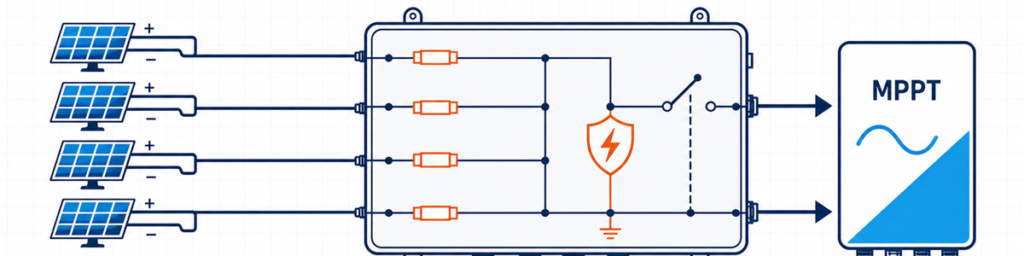
Empat string PV terhubung melalui kotak penggabung surya ber-sekering ke input MPPT inverterKotak penggabung surya harus sesuai dengan jumlah string PV yang kompatibel yang memberi masukan ke satu input inverter, tegangan rangkaian terbuka cuaca dingin tertinggi dari larik, arus desain berbasis Isc gabungan, dan proteksi yang diperlukan di lokasi tersebut. Jumlah input saja tidak cukup. Empat string mungkin memerlukan satu kotak 4-masuk/1-keluar, dua sirkuit 2-masuk/1-keluar terpisah, atau tanpa penggabung eksternal sama sekali, tergantung pada inverter dan tata letak kabel.
Bagi pembeli, “4 string, 1000 V” terdengar seperti spesifikasi yang dapat digunakan. Bagi insinyur yang memeriksa penawaran, itu hanyalah permulaan. Lembar data modul mungkin menunjukkan bahwa string mendekati 1000 V pada pagi yang dingin. Inverter mungkin menetapkan string ke dua MPPT independen. Jalur keluaran mungkin perlu mengalirkan hampir 70 A setelah faktor arus proyek diterapkan. Salah satu dari fakta tersebut dapat mengubah kotak.
Tujuannya di sini adalah mengubah informasi yang sudah ada pada lembar data modul, jadwal inverter, dan diagram satu garis menjadi spesifikasi awal yang dapat dipertahankan. Untuk konfigurasi umum dan opsi produk yang tersedia, lihat rangkaian kotak penggabung PV JUTRION.
Mulai dari Gambar Inverter, Bukan Jumlah String di Atap
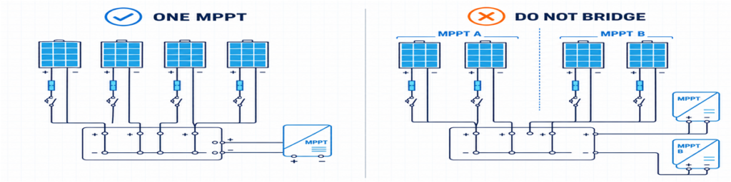
Pengelompokan string PV yang benar untuk satu MPPT dibandingkan dengan menjembatani input MPPT terpisah secara keliruString yang masuk ke satu keluaran penggabung harus memiliki tujuan yang valid. Kedengarannya jelas, namun di sinilah banyak penawaran awal salah.
Misalkan sebuah atap memiliki delapan string. Gambar inverter menetapkan empat ke MPPT A dan empat ke MPPT B. Meminta penggabung 8-masuk/1-keluar akan menggabungkan dua sirkuit yang dirancang inverter untuk dikendalikan secara independen. Pilihan yang dapat diterapkan biasanya dua kelompok terpisah 4-masuk/1-keluar, satu penutup yang berisi dua bagian independen secara elektrik, atau koneksi string langsung jika inverter sudah menyediakan input dan perlindungan yang sesuai.
String yang dimaksudkan untuk beroperasi secara paralel juga harus benar-benar kompatibel. Periksa jenis modul, modul per string, orientasi, dan bayangan yang diharapkan. Panjang string yang tidak sama memiliki tegangan operasi yang berbeda. Menggabungkan string yang sangat teduh dan tidak teduh juga dapat menghasilkan kecocokan operasi yang buruk bahkan ketika label modul identik.
Ini memberikan aturan pertama yang dapat digunakan:
Hitung string yang ditetapkan ke satu jalur MPPT yang kompatibel, bukan setiap string yang terlihat pada gambar proyek.
Ketika Penggabung Eksternal Menambah Sedikit Nilai
Banyak inverter string sudah menyediakan beberapa input DC, perlindungan lonjakan internal, dan fungsi isolasi DC. Jika setiap string dapat berjalan langsung ke input inverter yang sesuai, menambahkan penggabung eksternal dapat menciptakan terminasi kabel tambahan tanpa memecahkan masalah desain.
Kotak string tunggal adalah kasus terkait tetapi berbeda. Unit 1-masuk/1-keluar tidak menggabungkan arus; ia bertindak sebagai kotak perlindungan dan isolasi eksternal. Itu dapat berguna ketika inverter jauh, titik isolasi lokal diperlukan, atau proyek menginginkan perlindungan lonjakan yang dapat diganti di lokasi yang dapat diakses.
Lima Angka yang Layak Ditaruh di Satu Lembar
Sebelum melihat ukuran sekering atau dimensi penutup, kumpulkan lima kelompok informasi. Sebagian besar dapat disalin langsung dari dokumen proyek yang diterbitkan.
| Informasi | Dari mana biasanya berasal | Apa yang diubahnya |
|---|---|---|
| Voc, Isc, Imp, koefisien suhu, dan sekering seri maksimum | Lembar data modul PV | Batas tegangan, arus, dan sekering string |
| Modul per string dan jumlah string paralel | Jadwal string | Jumlah input dan total tegangan/arus |
| Susunan MPPT dan batas input | Lembar data inverter dan diagram satu garis | String mana yang boleh berbagi output |
| Suhu minimum, pemasangan, dan paparan | Dasar desain proyek dan data lokasi | Voc dingin, derating, dan enclosure |
| Negara tujuan dan aturan yang berlaku | Spesifikasi proyek | Metode proteksi dan dokumentasi |
Satu nilai yang sering terlewat adalah arus hubung singkat maksimum yang diizinkan inverter. Arus operasi maksimum dan arus hubung singkat maksimum tidak dapat dipertukarkan. Larik yang diusulkan harus diperiksa terhadap keduanya.
Negara tujuan sama pentingnya dengan data kelistrikan. Perhitungan sekering yang disiapkan untuk proyek berorientasi IEC tidak boleh diam-diam meminjam pengali Amerika Utara dan menyajikannya sebagai aturan universal.
Periksa Tegangan String Dingin Sebelum Memilih 1000 V atau 1500 V
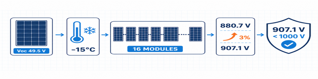
Perhitungan Voc string PV cuaca dingin untuk 16 modul menghasilkan tegangan desain 907,1 VVoc modul biasanya dinyatakan pada kondisi uji standar. Nilainya naik saat suhu sel turun, sehingga kondisi terdingin yang diperkirakan mengendalikan tegangan string maksimum.
Jika lembar data modul memberikan koefisien suhu Voc negatif sebagai persentase per derajat Celsius, perhitungan awal adalah:
Voc,dingin = Voc,STC × [1 + |βVoc| × (25 − Tmin)]
Vstring,dingin = Voc,dingin × jumlah modul dalam rangkaian seri
Masukkan koefisien sebagai desimal. Misalnya, −0,28%/°C menjadi 0,0028 dalam rumus. Jika produsen modul menyediakan metode suhu rendah yang berbeda, gunakan metode tersebut.
Jawabannya harus sesuai dengan lebih dari sekadar inverter. Link sekering dan pemegangnya, SPD, sakelar-pemisah atau pemutus, terminal, konduktor, dan rakitan lengkap semuanya berada di sirkuit DC yang sama. Mengganti hanya SPD dengan perangkat 1500 V tidak mengubah kotak 1000 V menjadi rakitan 1500 V.
Sedikit margin tegangan yang tidak terpakai bukanlah kapasitas yang terbuang. Margin tersebut menyerap basis suhu spesifik proyek dan toleransi yang telah benar-benar diidentifikasi. Yang harus dihindari adalah margin acak tanpa sumber yang tercatat.
Sekering String Bergantung pada Arus Balik, Bukan pada Kebiasaan
Ketika string paralel sehat, masing-masing menyumbangkan arus ke keluaran bersama. Jika satu string mengalami gangguan, string lainnya dapat mengalirkan arus balik ke dalamnya. Sekering string ada untuk memutus arus balik yang merusak tersebut di tempat yang memerlukan proteksi.
Penyaringan awal untuk kontribusi dari string lainnya adalah:
Iarus,balik,penyaringan = (n − 1) × Isc,string
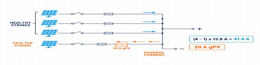
Arus balik dari tiga string PV sehat ke string yang terganggu yang dilindungi oleh sekering gPV 20 ADi sini, n adalah jumlah string paralel. Ekspresi tersebut menunjukkan mengapa jawabannya berubah cepat antara dua dan empat input: string yang terganggu dalam kelompok empat string dapat menerima arus dari tiga string sehat.
Jangan perlakukan ekspresi tersebut sebagai desain proteksi akhir. Sekering gPV yang dipilih harus mengalirkan arus yang diharapkan dalam kondisi enklosur aktual, melindungi kabel dan peralatan, tetap dalam batas peringkat sekering seri maksimum modul, dan memiliki tegangan DC PV serta kemampuan pemutusan yang memadai. Pemegang dan sekering diperiksa bersama, termasuk efek suhu dan pengelompokan.
IEC 60269-6 mencakup persyaratan tambahan untuk link sekering yang digunakan dalam string dan larik fotovoltaik hingga 1500 V DC. Aturan instalasi yang diadopsi untuk proyek menentukan bagaimana produk tersebut diterapkan.
Tentang Angka 1,56 × Isc yang Terlihat Online
Angka 1,56 × Isc yang umum dikenal terkait dengan dua faktor 125% yang digunakan dalam jalur desain umum di Amerika Utara. Angka ini tidak boleh dilabeli ulang sebagai rumus IEC universal. Jika proyek diatur oleh NEC, gunakan edisi yang diadopsi, daftar peralatan, dan persyaratan setempat. Jika ini adalah proyek IEC, terapkan aturan instalasi berbasis IEC yang relevan serta petunjuk dari produsen modul, sekring, dan kabel.
Perbedaan ini layak dinyatakan dalam penawaran. Jika tidak, dua pemasok dapat memberikan ukuran sekring yang berbeda meskipun keduanya menerima data larik yang sama.
Tentukan Jalur Gabungan Secara Terpisah dari Setiap Masukan
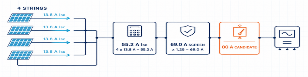
Empat string PV 13,8 A digabungkan menjadi 55,2 A Isc dengan saringan desain 69 A dan kandidat perangkat keluaran 80 ASisi masukan dan keluaran mengalirkan arus yang berbeda. Setiap masukan mengalirkan satu string; keluaran bersama mengalirkan jumlah dari string paralel.
Isc,total = jumlah string paralel × Isc,string
Faktor desain dan faktor koreksi yang disyaratkan proyek kemudian diterapkan pada konduktor dan peralatan yang sesuai. Hasilnya memengaruhi kabel internal, busbar, terminal, kabel keluar, dan perangkat sakelar keluaran. Hasil ini juga perlu dibandingkan dengan batas yang dinyatakan inverter.
Menggunakan Imp saja untuk seluruh pemilihan dapat membuat jalur proteksi terlalu kecil. Menggunakan Isc saja tanpa memeriksa arus MPPT normal inverter dapat melewatkan batasan operasi. Pisahkan nilai-nilai tersebut dan berikan masing-masing tujuan.
| Nilai | Gunakan untuk memeriksa |
|---|---|
| Imp String | Arus operasi normal dan kompatibilitas MPPT inverter |
| Isc String | Arus desain string dan perhitungan proteksi arus lebih |
| Total Isc | Jalur gabungan dan batas arus hubung singkat inverter |
| Arus desain proyek terkoreksi | Konduktor, busbar, terminal, dan perangkat keluaran pada kondisi terpasang |
Panas dapat mengesampingkan peringkat katalog yang tampaknya nyaman. Dudukan sekring yang dikelompokkan rapat, rugi-rugi terminal, SPD, dan radiasi matahari langsung semuanya menambah suhu dalam selungkup. Perangkat 80 A pada kondisi referensi tidak otomatis menjadi solusi 80 A di dalam setiap kotak luar ruangan.
Sekring, Isolasi, Pemutus, dan SPD Memiliki Tugas yang Berbeda
Kotak penggabung lebih mudah ditentukan spesifikasinya ketika setiap komponen memiliki satu tugas yang jelas:
- Sekring gPV: melindungi satu string terhadap kondisi arus balik lebih yang berlaku;
- sakelar-pemisah: menyediakan pemutusan beban berperingkat DC PV dan titik isolasi yang terdefinisi;
- pemutus sirkuit DC: menyakelar sirkuit dan menyediakan fungsi arus lebih ketika karakteristik dan peringkat pemutusan DC-nya sesuai dengan aplikasi;
- SPD DC PV: membatasi tegangan lebih transien dan tidak menggantikan proteksi arus lebih atau isolasi.
Pemutus keluaran tidak wajib hanya karena ada ruang untuk satu. Desain sistem dapat memerlukan sakelar-pemisah jika proteksi arus lebih sudah disediakan di tempat lain, atau pemutus dengan tugas proteksi yang terdefinisi. Tentukan fungsinya terlebih dahulu.
The same principle applies to the SPD. Confirm the PV DC application, UCPV, protection modes, protection level, discharge-current duty, short-circuit behaviour and backup coordination. Type 2 is commonly used for induced surge conditions. Where an external lightning protection system or another lightning-current path is present, the arrangement may need Type 1 or Type 1+2 protection. See the JUTRION PV DC SPD range after the project voltage and lightning context are known.
For the isolating function, a device rated for the intended PV duty is more meaningful than a generic “DC switch” description. The JUTRION PV DC isolator range includes DC-PV2 options for review against the required voltage, current and pole arrangement.
A Four-String Example from Datasheet to Box
Illustrative example: This is a constructed commercial-rooftop case used to show the calculation. It is not a customer project or a universal design.
Four identical strings are assigned to one high-current inverter input. Each string contains 16 modules. The module datasheet gives Voc = 49.5 V, Isc = 13.8 A, βVoc = −0.28%/°C and a maximum series-fuse rating of 25 A. The project minimum temperature is −15°C. Its design basis also applies a stated 3% allowance after the temperature calculation.
The illustrative inverter has a 1000 V maximum DC input, an 80 A maximum input current and a 100 A maximum short-circuit current. No external lightning protection system is assumed.
The Drawing Points to Four Inputs and One Output
All four strings use the same modules and string length, and the inverter documentation permits them to feed the same input. A 4-in/1-out architecture is therefore appropriate at this stage. If the drawing divided them between two MPPTs, the answer would become two independent 2-in/1-out groups.
The Cold String Reaches 907.1 V
Cold module Voc = 49.5 × [1 + 0.0028 × (25 − (−15))] = 55.04 V
Cold string Voc = 55.04 × 16 = 880.7 V
Project design voltage = 880.7 × 1.03 = 907.1 V
A verified 1000 V assembly can pass this preliminary check, as can the illustrative inverter. The remaining margin is about 93 V. A seventeenth module would raise the result to approximately 964 V before the same allowance and would not pass this example after the allowance is applied.
Parallel Strings Make Individual Fusing Necessary
The other three strings can contribute an initial reverse-current screen of:
(4 − 1) × 13.8 = 41.4 A
Itu berada di atas nilai maksimum sekering seri modul 25 A, sehingga perlindungan string individual diperlukan dalam contoh ini. Metode proyek menghasilkan penyaringan awal arus sekering yang lebih rendah sebesar 1,25 × 13,8 = 17,25 A. Sekering gPV 20 A berada di antara nilai tersebut dan batas modul 25 A. Sebelum diterima, dudukan sekering, perlindungan kabel, suhu selungkup, dan kemampuan arus kontinu harus diperiksa.
The Common Output Needs More Than a 55.2 A Label
The combined short-circuit current is:
4 × 13.8 = 55.2 A
The example design basis uses 1.25 × Isc as its preliminary output-current screen:
1.25 × 55.2 = 69.0 A
Sakelar pemutus DC PV 80 A adalah kerangka awal yang wajar, bukan pilihan akhir otomatis. Peringkat termal terpasang, tegangan, kutub, dan tugas pensakelaran masih harus diperiksa. Batas hubung singkat inverter 100 A lolos dari perbandingan 55,2 A. Batas operasi 80 A-nya harus dibandingkan dengan empat kali Imp modul dari lembar data sebenarnya.
The preliminary box is now specific enough to review: four independently fused inputs, one combined output, 1000 V-class components throughout, a combined path designed around the stated 69 A screen, PV DC isolation and a Type 2 PV DC SPD subject to final coordination.
The Result on One Page
The calculation is easier to review when the assumptions, result and remaining check are kept together. This is also the point where a buyer can see whether two quotations are actually based on the same duty.
| Selection item | Illustrative result | What still needs confirmation |
|---|---|---|
| Konfigurasi | 4 inputs / 1 output | All four strings feed one compatible inverter input |
| Maximum project voltage | 907.1 V | Site temperature basis, tolerance method and inverter limit |
| String protection | 20 A gPV preliminary selection | Fuse-holder temperature, cable protection and applicable rules |
| Combined short-circuit current | 55.2 A | Inverter maximum permissible short-circuit current |
| Preliminary output-current screen | 69.0 A | Correction factors and installed assembly temperature |
| Output isolation | 80 A frame is a starting candidate | PV DC duty, voltage, poles and installed current rating |
| Surge protection | Type 2 PV DC SPD initially | Ucpv, protection modes, LPS and backup coordination |
| Enclosure | Outdoor IP65 minimum | UV, corrosion, heat, glands and condensation |
Choosing Between a 1/1, 2/1 and 4/1 Configuration
JUTRION currently displays 1000 V DC, IP65 products in 1-in/1-out, 2-in/1-out and 4-in/1-out configurations. Use the input count to shortlist the architecture, then confirm the ratings that the project calculation produced.
| Konfigurasi | Typical reason to shortlist it | Reason to stop and reconsider |
|---|---|---|
| 1 input / 1 output | One string needs an accessible protection and isolation point | No combining occurs; verify that a separate box adds a required function |
| 2 inputs / 1 output | Two matched strings feed one inverter input | The strings belong to separate MPPTs or exceed the combined-input limits |
| 4 inputs / 1 output | Four matched strings feed one suitably rated high-current input | The inverter needs two MPPT groups or the output path is underrated |
The worked example points toward a JUPV1000-4/1 architecture. It does not approve the internal fuse, output device or SPD by model name alone. Those parts have to be quoted against the 907.1 V project voltage, the proposed 20 A gPV string protection, the 69 A preliminary combined-current screen and the outdoor installation conditions.
Custom 1500 V or larger-string configurations deserve a fresh component and assembly check. They should not be treated as a label change to the 1000 V stock arrangement.
The Outdoor Enclosure Can Change the Current Rating
Electrical calculations are often completed in an office at 25°C. The box may spend its working life on a roof where the air is much hotter, direct sunlight warms the enclosure, and several fuse-holders carry current side by side. That difference affects more than comfort during maintenance.
Heat is produced at fuses, terminals, conductors, the SPD and the output device. Closely packed components have less opportunity to cool, while a sealed enclosure restricts air exchange. A component that carries its marked current under its reference conditions may require derating in the final assembly. This is why the 80 A switch-disconnector in the example remains a starting frame until the installed arrangement has been checked.
IP65 is useful, but it answers only an ingress-protection question. It does not automatically establish:
- resistance to long-term ultraviolet exposure;
- corrosion performance near the coast or in an industrial atmosphere;
- acceptable internal temperature under full current and solar loading;
- condensation control during daily heating and cooling;
- suitability of cable glands, seals and materials for the installed cables;
- insulation performance at high altitude.
Mounting details also matter. Cable entries made through the top of an outdoor enclosure create a different water path from bottom entry. Undersized glands may damage seals or leave insufficient cable support. Tight cable bends can transfer mechanical force to fuse-holders and terminals. The enclosure should be reviewed as an installed assembly, not as an empty plastic or metal box with an IP number.
IEC 61439-2:2020 covers power switchgear and controlgear assemblies up to 1500 V DC. The relevance here is practical: using individually rated components does not remove the need to verify the completed assembly, including temperature rise, dielectric properties, protective circuits, clearances, wiring and mechanical construction as applicable.
Send Enough Information for the Supplier to Check the Result
A short technical enquiry is more useful than a long purchasing template. Attach the module and inverter datasheets and state:
- strings per output and modules per string;
- module Voc, Isc, Imp, βVoc and maximum series fuse;
- minimum design temperature and any voltage allowance;
- inverter MPPT arrangement and input limits;
- calculated maximum voltage and combined design current;
- required fuse, isolation, breaker and SPD functions;
- enclosure location, IP requirement, ambient, UV and corrosion exposure;
- cable sizes, monitoring, destination market and quantity.
For the illustrative project, that becomes: 4-in/1-out, four identical 16-module strings feeding one MPPT, 907.1 V stated project design voltage, preliminary 20 A gPV fuses, 55.2 A total Isc, 69 A preliminary output-current screen, PV DC isolation, coordinated Type 2 PV DC surge protection and an outdoor enclosure.
Why Two “4-String, 1000 V, IP65” Quotations May Not Be Equivalent
One quotation may use gPV fuse-links and holders verified for the intended voltage and temperature. Another may list only a nominal fuse current. One box may provide a load-break switch-disconnector; another may use a device intended mainly for isolation. SPD Ucpv, protection modes, short-circuit behaviour and replaceability may also differ even when both quotations say “Type 2 SPD.”
The common output is another source of hidden difference. Compare the installed current capability of the busbars, conductors, terminals and output device, not only the largest ampere number printed in the bill of materials. Also check terminal capacity against the actual outgoing cable. A technically lower-priced quotation is not cheaper if it requires replacement glands, a larger enclosure or rework at site.
A useful comparison therefore normalizes the following items before price:
- input/output arrangement and MPPT grouping;
- maximum DC voltage of the complete path;
- string-fuse class, rating and module limit;
- combined current and installed temperature conditions;
- output device function and DC duty;
- SPD type, Ucpv, modes and coordination;
- terminal and cable-gland capacity;
- enclosure material and environmental suitability.
The final selection should read as one connected electrical path. If the quotation confirms only input count, nominal voltage and IP rating, it has not yet answered the sizing question.
Verify the Box After Installation
A correct design can still be compromised by reversed polarity, loose terminations, damaged glands or a string connected to the wrong input. Commissioning should follow the project procedure and component instructions, with the DC circuit isolated and tested by qualified personnel.
Before energizing the combined output, record:
- string identity, polarity and measured open-circuit voltage;
- whether measured string voltages are reasonably consistent with the design and with one another;
- terminal tightening completed to the specified torque;
- protective-conductor and bonding continuity where required;
- fuse type and rating in every populated way;
- SPD status indication and remote alarm contact, if fitted;
- operation and position indication of the isolating device;
- labels, unused-entry seals, gland compression and enclosure closure.
After the system has operated under representative load, inspect for abnormal heating, discoloration, odour, nuisance fuse operation or moisture. Where the project maintenance plan uses thermography, the baseline image is more useful when load and ambient conditions are recorded with it. The purpose is not to “prove” the design from one scan, but to leave a reference for later comparison.
IEC 62548-1:2023 provides the broader IEC design context for PV arrays, including DC wiring, protection, switching and earthing. The completed assembly also needs appropriate verification; IEC 61439-2:2020 covers power switchgear and controlgear assemblies up to 1500 V DC. PV DC SPD requirements are addressed by IEC 61643-31.
To compare the result with a JUTRION configuration, send the string schedule, module and inverter data, site temperature, protection requirements and destination standard through the PV combiner box page. That gives both sides something more reliable to discuss than “four strings, best price.”
Pertanyaan yang Sering Diajukan
How Many Solar Strings Require a Combiner Box?
There is no universal minimum. An external combiner is useful when compatible strings need to be paralleled before one inverter input, when it reduces long cable runs, or when the project needs a centralized location for fuses, isolation, surge protection or monitoring. If an inverter already accepts every string directly and provides the required functions, a separate combiner may not be necessary.
What Size Fuse Should Be Used in a Solar Combiner Box?
Select a PV-rated gPV fuse from the string Isc, applicable installation method, cable capacity, environmental conditions and module maximum series-fuse rating. The fuse must carry expected current without nuisance operation while remaining low enough to protect the module and cable. Do not apply 1.56 × Isc as a universal IEC rule; the calculation depends on the destination standard.
Can Strings Connected to Different MPPTs Share One Combiner Box?
They may share a physical enclosure only if the MPPT circuits remain electrically separate. Do not combine the outputs of independent MPPT groups unless the inverter manufacturer explicitly permits that architecture. Each group should have its own compatible strings, output path and ratings.
Do I Need a 1000V or 1500V PV Combiner Box?
Calculate the maximum cold-weather open-circuit voltage of the complete string and include the allowances required by the project method. Select a voltage class that keeps the inverter and every component in the combiner path within rating. A 1500 V SPD alone does not make the completed box suitable for 1500 V.
What Is the Difference Between a PV Combiner Box and a PV Protection Box?
A PV combiner box joins two or more compatible string inputs into a common output. A 1-in/1-out PV protection box does not combine strings; it provides a convenient location for functions such as isolation, surge protection or overcurrent protection on one string circuit.
