

MCB مقابل MCCB مقابل RCCB مقابل RCBO: ما الفرق؟
يمكن أن يتطلب حدوث دائرة قصر في مقبس وتسرب عبر عزل تالف حمايات مختلفة، حتى عندما يحدثان على نفس الكابل. لهذا السبب قد تحتوي لوحة التوزيع على عدة أنواع من قواطع الدائرة.
الفرق الرئيسي بين MCB وMCCB وRCCB وRCBO هو نوع الحماية التي يوفرها كل منها. يحمي MCB من الحمل الزائد ودائرة القصر. يوفر MCCB حماية من التيار الزائد لمهام التوزيع التي قد تحتاج إلى تصنيفات أكبر أو إعدادات قابلة للتعديل أو قدرة أكبر على قطع الأعطال. يكتشف RCCB التيار المتبقي لكن ليس لديه حماية مدمجة من التيار الزائد. يجمع RCBO بين الحماية من التيار المتبقي والحمل الزائد ودائرة القصر.
بالنسبة لمقاول يقارن اللوحات، أو موزع يقارن عروض الأسعار، فإن السؤال المفيد هو إذن ما الوظائف التي تحتاجها كل دائرة. شراء أربعة أجهزة بنفس تصنيف الأمبير لن يجعلها قابلة للتبادل.
مقارنة بين MCB وMCCB وRCCB وRCBO
| المقارنة | MCB | MCCB | RCCB | RCBO |
|---|---|---|---|---|
| الاسم الكامل | قاطع الدائرة المصغر | قاطع الدائرة ذو الغلاف المقولب | قاطع الدائرة المعمل بالتيار المتبقي بدون حماية مدمجة من التيار الزائد | قاطع الدائرة المعمل بالتيار المتبقي مع حماية مدمجة من التيار الزائد |
| الحمل الزائد ودائرة القصر | نعم | نعم، مع وحدة الفصل المحددة | لا | نعم |
| الكشف عن التيار المتبقي | لا | يتطلب وظيفة مدمجة مناسبة أو ترتيبًا مرتبطًا | نعم | نعم |
| ضبط الحماية | عادة ثابت؛ اختر تصنيف التيار والمنحنى | ثابت أو قابل للتعديل، حسب وحدة الفصل | عادة حساسية ثابتة؛ لا يوجد إعداد للحمل الزائد | عادة تيار ومنحنى وحساسية ثابتة |
| إطار IEC الشائع | 60898-1؛ بعض المنتجات لديها أيضًا تصنيفات 60947-2 | 60947-2 | 61008-1 | 61009-1 |
| الموضع النموذجي | الدائرة النهائية أو مغذي صادر صغير | مغذي رئيسي أو مغذي توزيع أو حمل أكبر | غالبًا مجموعة دوائر، مع حماية منفصلة من التيار الزائد | عادة دائرة نهائية فردية |
| السبب الرئيسي لاختياره | حماية مدمجة من التيار الزائد | واجب العطل المطلوب أو ميزات التعديل أو التحكم | حماية متبقية مشتركة حيث يكون فصل المجموعة مقبولًا | حماية مدمجة مع عزل الأعطال على مستوى الدائرة |
RCD هو اسم العائلة. تعني جهاز التيار المتبقي وتشمل كل من RCCBs وRCBOs. المصطلحات غير الرسمية مثل RCB، والاستخدام غير المتسق لـ ELCB، قد تجعل الاقتباس غامضًا. حدد وظائف الحماية الفعلية ومعيار المنتج بدلاً من افتراض أن كل جهاز موصوف بأنه "قاطع تسرب التيار الأرضي" هو نفسه.
ماذا يحدث أثناء الحمل الزائد ودائرة القصر والتسرب الأرضي؟
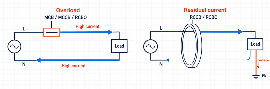
الحمل الزائد هو تيار مفرط في دائرة طبيعية فيما عدا ذلك. توصيل أحمال كثيرة جدًا يمكن أن يسخن الكابل دون إنشاء دائرة قصر مباشرة. يستجيب MCB الحراري المغناطيسي التقليدي من خلال عنصره الحراري؛ قد يستخدم MCCB حماية حرارية مغناطيسية أو إلكترونية. يتضمن RCBO أيضًا وظيفة التيار الزائد. لا يحدد RCCB وحده هذه الزيادة المتوازنة في تيار الحمل.
تخلق دائرة القصر مسارًا بمقاومة أقل بكثير. يمكن أن ينتج عطل خط إلى محايد أو خط إلى خط تيارًا أعلى بكثير من الحمل الطبيعي. يجب على الجهاز الواقي بدء الفتح وقطع ذلك التيار بأمان. تصف قدرته على القطع واجب القطع؛ الرقم بجانب المقبض الذي يصف تيار الحمل الطبيعي لا يفعل ذلك.
التيار المتبقي هو عدم توازن في التيارات المارة عبر ترتيب الاستشعار. في دائرة أحادية الطور، يجب أن يعود التيار الخارج عبر الخط عبر المحايد. إذا عاد جزء عبر مسار آخر، يمكن لـ RCCB أو RCBO اكتشاف الفرق. تقوم الأجهزة ثلاثية الطور بتقييم مجموع تيارات الموصلات الحية ذات الصلة بدلاً من مقارنة طور واحد فقط بالمحايد.
يمكن أن يشغل عطل أرضي قاطع تيار زائد عندما يسمح مسار العطل بتيار كافٍ. لذلك من غير الدقيق القول إن MCB لا يمكنه أبدًا إزالة عطل أرضي. القيد هو أن MCB ليس لديه وظيفة استشعار مخصصة للتيار المتبقي ولا يمكنه استبدال حماية RCD المطلوبة.
وبالمثل، لا تغطي الحماية من التيار المتبقي كل حالات الصعق الكهربائي. قد لا يخلق شخص يلامس الخط والمحايد عدم التوازن اللازم لتشغيل RCD. يظل التأريض والعزل وتدابير الحماية الأخرى جزءًا من التركيب. دليل التركيبات الكهربائية حول حماية RCD الإضافية يشرح هذا التمييز.
MCB مقابل MCCB: من أين تبدأ الفروق العملية
اختر MCB عندما تناسب خاصية ثابتة الدائرة
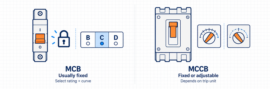
عادة ما يكون MCB الخيار المباشر للإضاءة ومقابس المآخذ ودوائر الصادر الأخرى الأصغر. يجعله شكله المدمج وخاصية التشغيل المحددة مسبقًا مناسبًا للتكرار عبر اللوحة. تتمثل مهمة التصميم في مطابقة تصنيف التيار ومنحنى التشغيل والجهد وواجب العطل لكل دائرة.
لا تستخدم 63 A أو 100 A كحد فاصل عالمي بين MCBs وMCCBs. تصنيفاتها تتداخل. نطاق الاستخدام يعتمد على التطبيق والخصائص الفنية. IEC 60898-1 يتضمن قواطع AC حتى 125 A وقدرات دائرة قصر حتى 25 kA. لا تصف حدود النطاق هذه كل منتج متاح.
قارن تصنيفات الأمبير وسعة القطع بشكل منفصل: يمكن أن يكون لقاطعتين MCB بتيار 32 A قدرات قطع مختلفة.
اختر قاطع دائرة مُقوَّل الحالة (MCCB) عندما تتطلب مهمة التوزيع مرونة أكبر
يصبح قاطع الدائرة المُقوَّل الحالة (MCCB) جاذبًا عندما تتطلب الدائرة نطاق ضبط أوسع، أو موصلات أكبر، أو واجب عطل مختلف، أو التكامل مع نظام التوزيع الأوسع. تتيح وظائف الوقت الطويل والوقت القصير القابلة للضبط، حيثما توفرت، للمصمم مواءمة الحماية مع تشغيل الحمل والأجهزة المتلقية.
حجم الهيكل وإعداد الحماية منفصلان. الإطار الذي يقبل تصنيفًا أقصى معينًا لا يتطلب أن يكون إعداد الحماية الزائد مساويًا لذلك الحد الأقصى. ومع ذلك، لا يكتسب MCCB ذو الرحلة الثابتة حماية قابلة للتعديل لمجرد أنه يحتوي على غلاف مصبوب. قارن وحدة الرحلة الفعلية.
قد تدعم ملامسات المساعدة ومفاتيح الفصل التحويلي ومشغلات المحرك المتوافقة مراقبة الحالة أو التشغيل عن بُعد. لهذه الملحقات وظائف مختلفة؛ فمفتاح الفصل التحويلي يفتح القاطع لكنه لا يغلقه عن بُعد. دليل ملحقات قواطع الدائرة JUTRION يشرح الوظائف المتاحة ومتطلبات المطابقة.
المعاملات التي تغيّر الاختيار
يحتاج المقارنة المفيدة إلى أكثر من قائمة بنطاقات الأمبير النموذجية. تجيب المعاملات التالية عن أسئلة مختلفة وينبغي أن تبقى منفصلة في المواصفات.
| المعلمة | المعنى وشرط التشغيل | المثال ونتيجة القرار |
|---|---|---|
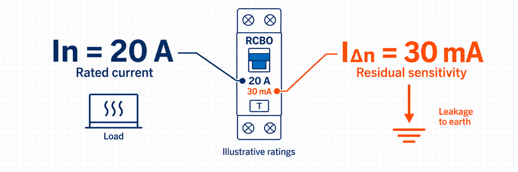
| التيار المقنن، In | قدرة التيار المعلنة في ظل ظروف محددة؛ تؤثر درجة الحرارة والتركيب على التحميل القابل للاستخدام | 32 A هو تصنيف تيار الحمل. على RCCB لا يعني أن هناك فصلًا عند حمل زائد 32 A. |
| إعداد الحمل الزائد، Ir | إعداد الحماية طويلة الوقت القابل للضبط حيثما توفر وحدة الفصل ذلك | يجب أن يحمي إعداد المغذي الكابل ويدعم الحمل؛ واختياره بناءً على حجم الهيكل وحده قد يترك الكابل غير محمي بشكل كافٍ. |
| جهد التشغيل، Ue | الجهد وتطبيق AC/DC الذي يتم الإعلان عن أدائه | لا يمكن تطبيق قيمة سعة القطع عند 230 فولت تلقائيًا عند 400 فولت أو على DC. |
| Icn وIcu وIcs | تصنيفات أداء الدائرة القصيرة بتعريفات قياسية وواجبات اختبار مختلفة | يجب مقارنة قيمة 6 kA مع مستوى الخطأ والمعيار المذكور؛ فهي ليست تصنيف تيار عادي 6,000 A. |
| تيار التشغيل المتبقي، IΔn | الحساسية المقننة لوظيفة التيار المتبقي | 30 mA تساوي 0.03 A. تصف حساسية عدم التوازن، بغض النظر عن تصنيف الحمل 20 A أو 63 A. |
| المنحنى ونوع قاطع التيار المتبقي (RCD) | B/C/D تتعلق بسلوك التيار الزائد اللحظي؛ AC/A/F/B تتعلق بأشكال موجات التيار المتبقي | يجمع قاطع الدائرة المصغرة مع حماية التيار المتبقي (RCBO) بمنحنى C ونوع A بين خاصيتين منفصلتين. تغيير منحناه لا يغيّر حساسيته الاسمية للتيار المتبقي. |
| الأقطاب والمحايد | أي الموصلات يتم فصلها واستشعارها وحمايتها من التيار الزائد | تحقق من المخطط لـ 1P+N أو 2P أو 3P+N أو 4P؛ فالتسميات المتشابهة لا تثبت سلوكًا متطابقًا للمحايد. |
اقرأ B وC وD كخصائص فصل، وليس كمستويات جودة
نطاقات التيار اللحظي الشائعة لقواطع الدائرة المصغرة وفق IEC هي تقريبًا 3–5 × In لـ B، و5–10 × In لـ C، و10–20 × In لـ Dلجهاز 16 A، تعطي نطاقات توضيحية 48–80 A، 80–160 A و160–320 A على التوالي. هذه هي نطاقات التشغيل، وليست نقطة التقاط مضمونة واحدة؛ المنحنى المختار للمنتج هو المسيطر.
يمكن للنطاق الأعلى استيعاب تيار بدء أكبر، لكنه يتطلب أيضًا تيار عطل كافيًا للتشغيل السريع. اختيار منحنى D لمجرد إيقاف الفصل المزعج قد يزيد أداء الفصل سوءًا. تحقق من مدة التيار المتدفق والتيار العطل المتاح معًا. شرح شرح الشركة المصنّعة لخصائص القاطع يوفر سياق التصنيف.
قارن قدرة القطع عند نقطة التركيب الفعلية
خذ بعين الاعتبار لوحة توضيحية بتيار دائرة قصيرة محتمل محسوب قدره 7.2 كيلو أمبير. قاطع دائرة مستقل بقدرة 6 كيلو أمبير لا يفي بواجب القطع هذا؛ وجهاز محدد بشكل صحيح بقدرة 10 كيلو أمبير يجتاز فحص القدرة الأولي هذا. لا تقول هذه المقارنة شيئًا بعد عن حماية الكابل أو التمييز.
يمكن أحيانًا استخدام جهاز أقل تصنيفًا في الأسفل مع حماية احتياطية مؤكدة في الأعلى. يتطلب ذلك تركيبة معلنة، وليس افتراض أن أي MCCB كبير يجعل كل قاطع في الأسفل مقبولًا. يجب مراجعة التوافق الفني بين الأجهزة. اختيار قاطع الدائرة تصف كلا المسارين.
بالنسبة لقواطع الدائرة المصغرة (MCCBs)، فإن Icu هو تيار القطع النهائي للدائرة القصيرة، ويصف Ics أداء القطع في خدمة الدائرة القصيرة. لا يكفي ارتفاع Icu وحده لتحقيق نفس واجب الخدمة الذي يوفره Ics مرتفع بالقدر نفسه. اقرأ كليهما عند الجهد المعني. أما تصنيف القطع المشروط لقاطع التيار المتبقي (RCCB)، فيعتمد على الجهاز الوقائي المرتبط المحدد له، ويجب ألا يُعامل على أنه قدرة القطع المستقلة لقاطع RCBO.
اختر حساسية التيار المتبقي وقدرة شكل الموجة معًا
عندما تكون هناك حاجة إلى حماية إضافية، 30 mA هو اختيار تصميم شائع. القيم مثل 100 mA و300 mA تخدم أغراض حماية أو تنسيق أخرى وليست بدائل قابلة للتبادل للحماية المطلوبة 30 mA. الرقم الأقل وحده لا يشكل اختيارًا كاملاً.
النوع AC يكتشف التيار المتبقي المتناوب الجيبي. النوع A يكتشف أيضًا التيار المستمر النابض. النوع F يعالج ظروف التردد المختلط المحددة، بينما النوع B يشمل الكشف عن التيار المستمر السلس ضمن أدائه المحدد. يمكن للمعدات التي تحتوي على محولات أو محركات تغيير نوع RCD المطلوب. اتبع تعليمات المعدات وقواعد سوق الوجهة بدلاً من الاختيار بناءً على تيار الحمل فقط. انظر تصنيفات شكل الموجة لقاطع الدائرة الكهربائية RCD للتمييز الفني.
RCCB بالإضافة إلى MCBs أم RCBOs فردية؟
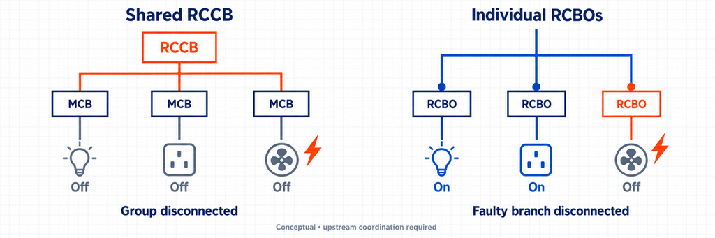
استخدم RCBOs فردية عندما يكون فقدان الدوائر غير المرتبطة مزعجًا. يظل RCCB مشترك مع MCBs منفصلة ترتيبًا عمليًا عندما يكون فصل المجموعة مقبولًا والحماية منسقة بشكل صحيح. قارن عواقب الخطأ قبل مقارنة أسعار المكونات.
قد تكون التكلفة الإضافية للجهاز جديرة بالاهتمام للتبريد أو معدات الدفع أو الإضاءة التي يجب أن تظل متاحة أثناء فحص دائرة أخرى. يوضح مثال الورشة أدناه كيف يغير هذا ترتيب اللوحة.
تحقق من إجمالي الحمل على قاطع RCCB المشترك. يمكن أن يتجاوز حمل الفرع المجمع قدرته الاستيعابية دون تجاوز تصنيف أي قاطع MCB منفرد. لذلك لا تحمي قواطع MCB الفرعية وحدها تلقائياً من الحمل الزائد؛ يجب أن يوفر الترتيب الكامل الحماية المطلوبة.
التسرب الطبيعي هو فرق آخر. يمكن للمعدات الإلكترونية أن تسهم في تيار الموصل الحامي أثناء التشغيل السليم. تجميع العديد من الدوائر تحت RCCB واحد يجمع سلوك التيار المتبقي لديهم عند ذلك الجهاز. تفصل RCBOs الفردية المجموعات، لكنها لا تصلح العزل التالف أو تلغي الحاجة لأخذ التسرب الطبيعي في الاعتبار.
يجب أن يتبع توجيه المحايد الترتيب المختار. يمكن أن يقوض المحايد المشترك عبر مجموعات محمية منفصلة التشغيل ويسبب فصلًا غير مرغوب فيه. لذلك، قد ينطوي التغيير إلى RCBO على أكثر من مجرد استبدال الأجهزة على سكة DIN.
بالنسبة لتركيب قائم، يجب على كهربائي مؤهل تقييم اللوحة والتمديدات قبل التحويل. بالنسبة للوحة جديدة، دليل اختيار قاطع RCBO من JUTRION يأخذ الخطوة التالية إلى نوع التيار المتبقي والحساسية وتكوين الموصلات.
ورشة صغيرة: مقارنة ترتيبي حماية
ما يلي مقارنة تصميم توضيحية، وليس تركيب عميل مكتمل. تحتوي الورشة على فروع منفصلة لسخان طاولة العمل والمقابس العامة والإضاءة وآلة ثابتة. يريد المالك أن يكون تأثير عطل السخان في أدنى حد ممكن على بقية الورشة.
ابدأ بفرع السخان. افترض حمل مقاوم أحادي الطور 4.6 kW عند 230 فولت، معامل القدرة تقريبًا واحد، وكابل بسعة حمل تيار مصححة 27 A. تيار الحمل هو:
Ib = P / U = 4,600 W / 230 V = 20 A.
هنا Ib هو تيار التصميم، P هي القدرة الكهربائية الداخلة وU هو جهد الإمداد. تصنيف حماية مقترح 25 A يمر بالعلاقة الأولية 20 A ≤ 25 A ≤ 27 A بين الحمل والقاطع وسعة الكابل المصححة. اختيار 32 A يفشل هذا الفحص لأنه يتجاوز سعة الكابل المذكورة. لا يزال يتعين فحص تخفيض تصنيف الجهاز وشروط حماية الموصل المتبقية.
إذا كانت الحماية من التيار المتبقي مطلوبة، يحتفظ كلا الترتيبين أدناه بتصنيف الفرع المقترح 25 A. يتم اختيار الحساسية المطلوبة ونوع شكل الموجة بشكل منفصل.
الترتيب الأول يستخدم RCCB مشترك وMCB فرعية. للسخان حماية خاصة به من التيار الزائد، لكن عيبًا مؤهلًا في التيار المتبقي يمكن أن يقطع أيضًا التغذية عن الفروع الأخرى في الورشة. يتعارض هذا الترتيب مع تفضيل الاستمرارية المعلن من المالك إذا كانت الفروع الأربعة جميعها تشترك في ذلك القاطع RCCB.
يخصص الترتيب الثاني قاطع RCBO لكل دائرة نهائية مناسبة. يدعم هذا الفصل المستقل بشكل أفضل. ينتقل حساب حمل السخان دون تغيير؛ ما يتغير هو مكان عمل الحماية من التيار المتبقي. يجب أن يظل فرع الآلة متوافقًا مع متطلبات معداته، خاصة إذا كان يتضمن محركًا.
قد يستخدم المغذي العلوي قاطع MCCB إذا كان حمله أو ضبطه أو واجب العطل يبرر ذلك. لا يلزم أن يكون MCCB لمجرد أن المبنى يسمى ورشة. ولا يثبت تصنيف المغذي أنه سيبقى مغلقًا خلال كل عطل لاحق.
لمتطلبات استمرارية هذا المالك، اختر RCBO فردية للدارات النهائية المناسبة. حافظ على المتطلبات الخاصة بمعدات الآلة والتنسيق العلوي في التصميم.
ما يخبرك به معيار المنتج — وما لا يخبرك به
يحدد المعيار إطار اختبار المنتج؛ وتحدد قواعد التركيب كيفية استخدامه. لا يوفر رقم المعيار تيار التصميم أو تيار العطل المحتمل أو ترتيب الدائرة لمشروع معين.
يمكن أن يكون للجهاز تصنيفات تحت أكثر من معيار واحد. استخدم التصنيف المقابل للواجب المطبق بدلاً من اختيار رقم kA الذي يبدو الأكبر. تحدد مراجع كتالوج IEC في النهاية الوثائق التي تم الرجوع إليها، بما في ذلك إصدارات 2024 لـ IEC 60947-2 وIEC 61008-1 وIEC 61009-1.
تحقق من الإصدار المطبق أو الاعتماد الوطني في وثائق المنتج. بالنسبة لمشاريع أمريكا الشمالية، تأكد من القائمة المحلية المطلوبة وقواعد التركيب؛ لا يثبت مرجع IEC وحده القبول.
حافظ على عمل بقية اللوحة
يبقى سؤال النظام المتبقي هو الانتقائية: هل سيزيل الجهاز الأقرب إلى العطل العطل بينما تبقى الحماية العلوية مغلقة؟ لا يثبت تصنيف تيار علوي أكبر ذلك. تحقق من بيانات الانتقائية لدى الشركة المصنّعة للأجهزة المختارة ومستوى العطل. تعالج الحماية الاحتياطية قدرة القطع وهي مسألة مختلفة عن الانتقائية. الـ إرشادات تنسيق القواطع تشرح التمييز.
الأجهزة التي تكشف التيار المتبقي على التوالي تحتاج إلى تقييم تنسيق خاص بها، بما في ذلك الحساسية، سلوك الزمن وتوافق شكل الموجة. جهازان متطابقان 30 mA على التوالي لا يحققان التشغيل الانتقائي. استخدم إرشادات تنسيق RCD المعلنة بدلاً من التخمين من التصنيفات الاسمية.
أخيراً، تغطي هذه المقارنة الحماية من التيار الزائد والتيار المتبقي. لحماية الطفرة العابرة دور منفصل، موضح في دليل JUTRION SPD. إضافة قاطع RCBO لا تلغي سؤال التصميم ذلك.
عند مقارنة عرض اللوحة التالي، تتبع دائرة خروج واحدة من حملها إلى المصدر. حدد أي جهاز يقطع كل عطل وأي الدوائر السليمة تفقد الطاقة عند تشغيله. هذا يجعل الفروق بين MCB وMCCB وRCCB وRCBO ملموسة قبل طلب المعدات.
الأسئلة الشائعة
هل يمكن لـ RCCB أن يحل محل MCB؟
لا. يكشف RCCB التيار المتبقي لكنه لا يوفر حماية من الحمل الزائد أو الدائرة القصيرة. يحتاج إلى حماية منفصلة مناسبة ضد التيار الزائد. يجمع RCBO بين الوظيفتين عندما تناسب تصنيفاته الدائرة.
هل MCCB دائماً أفضل من MCB؟
لا. غالباً ما يكون MCB الخيار العملي لدائرة نهائية أصغر. يكون MCCB مفيداً عندما يتطلب التشغيل تصنيفات مختلفة أو حماية قابلة للضبط أو وظائف تحكم إضافية. اختر وفقاً للدائرة، لا وفقاً لحجم الحاوية.
هل ما زلت بحاجة إلى MCB إذا استخدمت RCBO؟
يتضمن RCBO المختار بشكل مناسب بالفعل حماية دائرة الفرع من الحمل الزائد والدائرة القصيرة، لذا لا تكون هناك حاجة عادةً إلى MCB آخر فقط لمضاعفة تلك الوظائف. تظل حماية المغذي العلوي والتنسيق سارية.
ما الفرق بين 63 A و30 mA على RCCB؟
63 A هي قدرته المقدرة على حمل التيار في الظروف المعلنة. 30 mA هو تيار التشغيل المتبقي المقدر. لا يمنح أي من العلامتين قاطع RCCB حماية مدمجة من الحمل الزائد؛ إذ يتطلب ذلك جهازًا وقائيًا منفصلًا.
هل ستمنع RCBOs الفردية تعطل اللوحة بأكملها؟
يمكنها عزل عيب التيار المتبقي في فرع واحد، مما يقلل الاضطراب في الدوائر السليمة. لكنها لا تضمن بقاء الحماية العلوية مغلقة. يعتمد ذلك على العطل وتنسيق الترتيب الكامل.
المراجع الفنية
