

MCB vs MCCB vs RCCB vs RCBO: แตกต่างกันอย่างไร?
การลัดวงจรที่เต้ารับและการรั่วไหลผ่านฉนวนที่เสียหายอาจต้องใช้การป้องกันที่แตกต่างกัน แม้ว่าจะเกิดขึ้นบนสายเคเบิลเดียวกันก็ตาม นั่นคือเหตุผลที่ตู้จ่ายไฟอาจมีเบรกเกอร์หลายชนิด.
ความแตกต่างหลักระหว่าง MCB, MCCB, RCCB และ RCBO คือการป้องกันที่แต่ละชนิดให้. MCB ป้องกันการโอเวอร์โหลดและลัดวงจร MCCB ให้การป้องกันกระแสเกินสำหรับหน้าที่จ่ายไฟที่อาจต้องใช้พิกัดที่ใหญ่กว่า การตั้งค่าที่ปรับได้ หรือความสามารถในการตัดกระแสผิดพร่องที่มากกว่า RCCB ตรวจจับกระแสตกค้างแต่ไม่มีการป้องกันกระแสเกินในตัว RCBO รวมการป้องกันกระแสตกค้าง โอเวอร์โหลด และลัดวงจรเข้าด้วยกัน.
สำหรับผู้รับเหมาที่เปรียบเทียบตู้ไฟ หรือผู้จัดจำหน่ายที่เปรียบเทียบใบเสนอราคา คำถามที่มีประโยชน์คือแต่ละวงจรต้องการฟังก์ชันใด การซื้ออุปกรณ์สี่ตัวที่มีพิกัดแอมแปร์เดียวกันจะไม่ทำให้สามารถใช้แทนกันได้.
เปรียบเทียบ MCB, MCCB, RCCB และ RCBO
| การเปรียบเทียบ | MCB | MCCB | RCCB | RCBO |
|---|---|---|---|---|
| ชื่อเต็ม | เบรกเกอร์วงจรขนาดเล็ก | เบรกเกอร์วงจรแบบ molded case | เบรกเกอร์วงจรกระแสตกค้างโดยไม่มีการป้องกันกระแสเกินในตัว | เบรกเกอร์วงจรกระแสตกค้างที่มีการป้องกันกระแสเกินในตัว |
| โอเวอร์โหลดและลัดวงจร | ใช่ | ใช่ ด้วย trip unit ที่ระบุ | No | ใช่ |
| การตรวจจับกระแสตกค้าง | No | ต้องมีฟังก์ชันในตัวที่เหมาะสมหรือการจัดวางที่เกี่ยวข้อง | ใช่ | ใช่ |
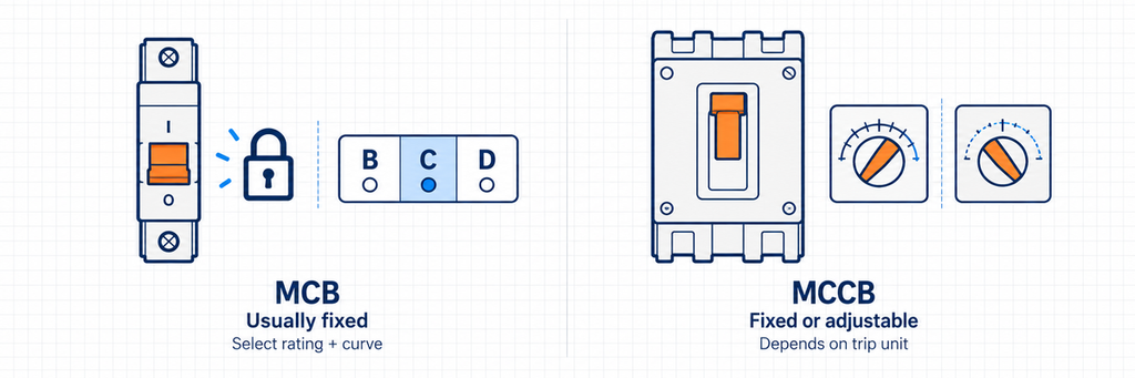
| การปรับการป้องกัน | โดยปกติคงที่ เลือกพิกัดกระแสและเส้นโค้ง | คงที่หรือปรับได้ ขึ้นอยู่กับ trip unit | โดยปกติความไวคงที่ ไม่มีการตั้งค่าโอเวอร์โหลด | โดยปกติกระแส เส้นโค้ง และความไวคงที่ |
| กรอบมาตรฐาน IEC ทั่วไป | 60898-1; บางผลิตภัณฑ์ยังมีพิกัด 60947-2 ด้วย | 60947-2 | 61008-1 | 61009-1 |
| ตำแหน่งทั่วไป | วงจรปลายทางหรือสายจ่ายออกขนาดเล็ก | สายเข้า สายจ่ายไฟจ่าย หรือโหลดที่ใหญ่กว่า | มักเป็นกลุ่มวงจร โดยมีการป้องกันกระแสเกินแยกต่างหาก | โดยปกติเป็นวงจรปลายทางแต่ละวงจร |
| เหตุผลหลักในการเลือก | การป้องกันกระแสเกินแบบกะทัดรัด | หน้าที่ผิดพร่องที่ต้องการ การปรับตั้ง หรือคุณสมบัติการควบคุม | การป้องกันกระแสตกค้างร่วมกันเมื่อการตัดการเชื่อมต่อทั้งกลุ่มเป็นที่ยอมรับได้ | การป้องกันแบบรวมกับการแยกความผิดพร่องระดับวงจร |
RCD เป็นชื่อตระกูล. หมายถึงอุปกรณ์กระแสรั่วและรวมทั้ง RCCB และ RCBO คำไม่เป็นทางการเช่น RCB และการใช้ ELCB ที่ไม่สอดคล้องกันอาจทำให้ใบเสนอราคากำกวม ควรระบุฟังก์ชันการป้องกันและมาตรฐานผลิตภัณฑ์ที่แท้จริงแทนการสมมติว่าอุปกรณ์ทุกชิ้นที่เรียกว่า “เบรกเกอร์รั่วไหลของโลก” เหมือนกันทั้งหมด
เกิดอะไรขึ้นระหว่างโอเวอร์โหลด ลัดวงจร และไฟรั่วดิน?
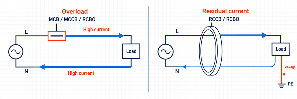
โอเวอร์โหลดคือกระแสที่มากเกินไปในวงจรที่ปกติในด้านอื่น ๆ. การเชื่อมต่อโหลดมากเกินไปสามารถทำให้สายเคเบิลร้อนได้โดยไม่สร้างการลัดวงจรโดยตรง MCB แบบ thermal-magnetic ทั่วไปตอบสนองผ่านองค์ประกอบความร้อน MCCB อาจใช้การป้องกันแบบ thermal-magnetic หรืออิเล็กทรอนิกส์ RCBO ยังมีฟังก์ชันกระแสเกินด้วย RCCB เพียงอย่างเดียวไม่สามารถระบุการเพิ่มขึ้นของกระแสโหลดที่สมดุลนี้ได้.
การลัดวงจรสร้างเส้นทางที่มีอิมพีแดนซ์ต่ำกว่ามาก. ความผิดพร่องแบบ line-to-neutral หรือ line-to-line สามารถสร้างกระแสที่สูงกว่าปกติมาก อุปกรณ์ป้องกันต้องทั้งเริ่มการเปิดและตัดกระแสนั้นอย่างปลอดภัย ความสามารถในการตัด (breaking capacity) อธิบายหน้าที่การตัด ตัวเลขข้างมือจับที่อธิบายกระแสโหลดปกติไม่ได้อธิบายสิ่งนั้น.
กระแสตกค้างคือความไม่สมดุลของกระแสที่ผ่านการจัดวางเซ็นเซอร์. ในวงจรเฟสเดียว กระแสที่ออกทางไลน์ควรกลับทางนิวทรัล หากส่วนหนึ่งกลับผ่านเส้นทางอื่น RCCB หรือ RCBO สามารถตรวจจับความแตกต่างได้ อุปกรณ์สามเฟสประเมินผลรวมของกระแสตัวนำมีไฟที่เกี่ยวข้อง แทนที่จะเปรียบเทียบเพียงเฟสเดียวกับนิวทรัล.
ความผิดพร่องดินสามารถทำให้เบรกเกอร์กระแสเกินทำงานได้เมื่อเส้นทางผิดพร่องยอมให้กระแสเพียงพอ ดังนั้นจึงไม่ถูกต้องที่จะกล่าวว่า MCB ไม่สามารถเคลียร์ความผิดพร่องดินได้เลย ข้อจำกัดคือ MCB ไม่มีฟังก์ชันตรวจจับกระแสตกค้างโดยเฉพาะ และไม่สามารถแทนที่การป้องกัน RCD ที่ต้องการได้.
เช่นเดียวกัน การป้องกันกระแสตกค้างไม่ได้ครอบคลุมทุกสถานการณ์ไฟฟ้าช็อต บุคคลที่สัมผัสไลน์และนิวทรัลอาจไม่สร้างความไม่สมดุลที่จำเป็นในการทำให้ RCD ทำงาน การต่อดิน ฉนวน และมาตรการป้องกันอื่นๆ ยังคงเป็นส่วนหนึ่งของการติดตั้ง คู่มือการติดตั้งไฟฟ้าเกี่ยวกับการป้องกัน RCD เพิ่มเติม อธิบายความแตกต่างนี้.
MCB vs MCCB: ความแตกต่างในทางปฏิบัติเริ่มต้นที่ไหน
เลือก MCB เมื่อคุณลักษณะคงที่เหมาะสมกับวงจร
MCB มักเป็นตัวเลือกที่ตรงไปตรงมาสำหรับแสงสว่าง เต้ารับ และวงจรจ่ายออกขนาดเล็กอื่นๆ รูปแบบกะทัดรัดและคุณลักษณะการทำงานที่กำหนดไว้ล่วงหน้าทำให้สะดวกในการใช้วนซ้ำทั่วทั้งตู้ งานออกแบบคือการจับคู่พิกัดกระแส เส้นโค้งการทำงาน แรงดัน และหน้าที่ผิดพร่องกับแต่ละวงจร.
อย่าใช้ 63 A หรือ 100 A เป็นขอบเขตสากลระหว่าง MCB และ MCCB เนื่องจากเรตติ้งของพวกเขาทับซ้อนกัน ขอบเขตของ IEC 60898-1 รวมเบรกเกอร์ AC สูงถึง 125 A และความสามารถในการลัดวงจรสูงถึง 25 kA ขีดจำกัดขอบเขตเหล่านี้ไม่ได้อธิบายทุกผลิตภัณฑ์ที่มีจำหน่าย.
เปรียบเทียบเรตติ้งแอมแปร์และความสามารถในการตัดวงจรแยกกัน: MCB 32 A สองตัวอาจมีความสามารถตัดวงจรสั้นต่างกัน.
เลือก MCCB เมื่อภาระงานด้านการจ่ายไฟต้องการความยืดหยุ่นมากขึ้น
MCCB จะน่าสนใจเมื่อวงจรต้องการช่วงการปรับที่กว้างขึ้น ตัวนำที่ใหญ่ขึ้น ภาระงานด้านความผิดพร่องที่แตกต่าง หรือการเชื่อมต่อกับระบบจ่ายไฟที่กว้างขึ้น ฟังก์ชันปรับได้แบบเวลานานและเวลาสั้น เมื่อมีให้ใช้งาน ช่วยให้นักออกแบบปรับการป้องกันให้เหมาะกับการทำงานของโหลดและอุปกรณ์ปลายน้ำ.
ขนาดโครงและค่าตั้งการป้องกันแยกจากกัน. โครงที่รองรับพิกัดสูงสุดค่าหนึ่งไม่จำเป็นต้องมีค่าตั้งโอเวอร์โหลดเท่ากับค่าสูงสุดนั้น อย่างไรก็ตาม MCCB แบบทริปคงที่ไม่ได้รับการป้องกันแบบปรับได้เพียงเพราะมีเปลือกหุ้มขึ้นรูป เปรียบเทียบหน่วยทริปจริง.
คอนแทคเสริม ชันต์ทริป และมอเตอร์โอเปอเรเตอร์ที่เข้ากันได้อาจรองรับการตรวจสอบสถานะหรือการทำงานระยะไกล อุปกรณ์เสริมเหล่านี้มีหน้าที่ต่างกัน ชันต์ทริปเปิดเบรกเกอร์แต่ไม่สามารถปิดเบรกเกอร์จากระยะไกลได้ คู่มืออุปกรณ์เสริมของเซอร์กิตเบรกเกอร์ JUTRION อธิบายฟังก์ชันที่มีและข้อกำหนดการจับคู่.
พารามิเตอร์ที่เปลี่ยนทางเลือก
การเปรียบเทียบที่มีประโยชน์ต้องการมากกว่ารายการช่วงกระแสไฟทั่วไป พารามิเตอร์ต่อไปนี้ตอบคำถามที่แตกต่างกันและควรแยกจากกันในข้อกำหนด.
| พารามิเตอร์ | ความหมายและเงื่อนไขการทำงาน | ตัวอย่างและผลลัพธ์ของการตัดสินใจ |
|---|---|---|
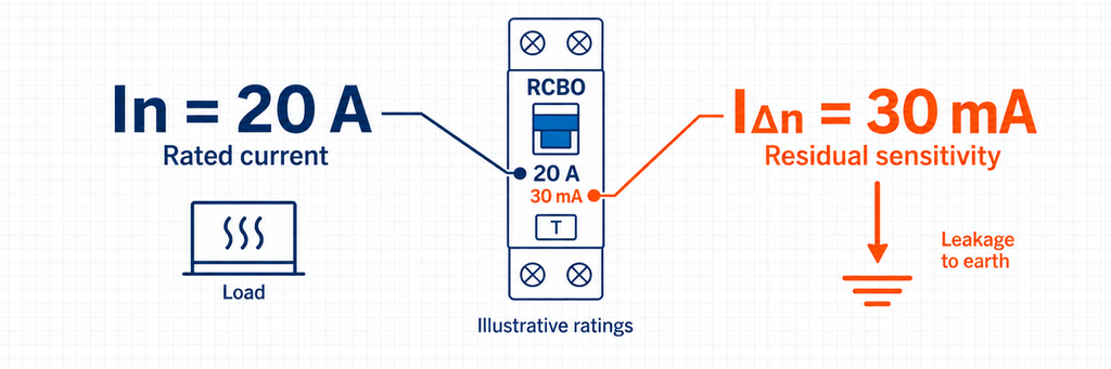
| กระแสไฟพิกัด, In | ความสามารถด้านกระแสไฟที่ประกาศภายใต้เงื่อนไขที่กำหนด อุณหภูมิและการติดตั้งส่งผลต่อการรับโหลดที่ใช้งานได้ | 32 A เป็นพิกัดกระแสโหลด บน RCCB ไม่ได้หมายความว่ามีการทริปโอเวอร์โหลด 32 A ให้. |
| ค่าตั้งโอเวอร์โหลด, Ir | ค่าตั้งการป้องกันเวลานานแบบปรับได้เมื่อหน่วยทริปมีให้ | ค่าตั้งสายป้อนต้องป้องกันสายเคเบิลและรองรับโหลด การเลือกจากขนาดโครงเพียงอย่างเดียวอาจทำให้สายเคเบิลได้รับการป้องกันไม่เพียงพอ. |
| แรงดันไฟฟ้าทำงาน, Ue | แรงดันไฟฟ้าและการใช้งาน AC/DC ที่ประกาศประสิทธิภาพ | ค่าความสามารถในการตัดที่ 230 V ไม่สามารถนำไปใช้ที่ 400 V หรือ DC ได้โดยอัตโนมัติ. |
| Icn, Icu และ Ics | พิกัดประสิทธิภาพการลัดวงจรที่มีนิยามมาตรฐานและภาระงานทดสอบต่างกัน | ค่า 6 kA ต้องเปรียบเทียบกับระดับความผิดพร่องและมาตรฐานที่ระบุ ไม่ใช่พิกัดกระแสปกติ 6,000 A. |
| กระแสทำงานตกค้าง, IΔn | ความไวพิกัดของฟังก์ชันกระแสตกค้าง | 30 mA เท่ากับ 0.03 A อธิบายความไวต่อความไม่สมดุล โดยไม่ขึ้นกับพิกัดโหลด 20 A หรือ 63 A. |
| เส้นโค้งและประเภท RCD | B/C/D เกี่ยวกับพฤติกรรมโอเวอร์กระแสทันที AC/A/F/B เกี่ยวกับรูปคลื่นกระแสตกค้าง | RCBO แบบเส้นโค้ง C ประเภท A รวมลักษณะสองอย่างที่แยกจากกัน การเปลี่ยนเส้นโค้งไม่เปลี่ยนความไวกระแสตกค้างตามพิกัด. |
| ขั้วและนิวทรัล | ตัวนำใดที่ถูกสับเปลี่ยน ตรวจจับ และป้องกันโอเวอร์กระแส | ตรวจสอบแผนภาพสำหรับ 1P+N, 2P, 3P+N หรือ 4P ป้ายที่คล้ายกันไม่ได้ยืนยันพฤติกรรมนิวทรัลที่เหมือนกัน. |
อ่าน B, C และ D เป็นลักษณะการทริป ไม่ใช่ระดับคุณภาพ
แถบทันทีของเบรกเกอร์ขนาดเล็ก IEC ทั่วไปอยู่ที่ประมาณ 3–5 × In สำหรับ B, 5–10 × In สำหรับ C และ 10–20 × In สำหรับ D. สำหรับอุปกรณ์ 16 A จะได้แถบตัวอย่างที่ 48–80 A, 80–160 A และ 160–320 A ตามลำดับ สิ่งเหล่านี้เป็นแถบการทำงาน ไม่ใช่จุดตรวจจับเดียวที่รับประกัน เส้นโค้งของผลิตภัณฑ์ที่เลือกเป็นตัวควบคุม.
แถบที่สูงขึ้นสามารถรองรับกระแสเริ่มต้นที่มากกว่า แต่ก็ต้องการกระแสความผิดพร่องที่เพียงพอสำหรับการทำงานอย่างรวดเร็ว การเลือกเส้นโค้ง D เพียงเพื่อหยุดการทริปที่ไม่พึงประสงค์อาจทำให้ประสิทธิภาพการตัดวงจรแย่ลง ตรวจสอบระยะเวลากระแสกระชากและกระแสความผิดพร่องที่มีอยู่พร้อมกัน คำอธิบายของผู้ผลิตเกี่ยวกับคุณลักษณะของเบรกเกอร์ ให้บริบทของพิกัด.
เปรียบเทียบความสามารถในการตัดที่จุดติดตั้งจริง
พิจารณาแผงตัวอย่างที่มีกระแสลัดวงจรคาดหวังที่คำนวณได้ 7.2 kA เบรกเกอร์ 6 kA แบบเดี่ยวไม่ตอบสนองภาระงานการตัดนั้น อุปกรณ์ 10 kA ที่ระบุอย่างถูกต้องผ่านการตรวจสอบความสามารถเบื้องต้นนี้ การเปรียบเทียบนี้ยังไม่ได้กล่าวถึงการป้องกันสายเคเบิลหรือการเลือกแยก.
อุปกรณ์ปลายน้ำที่มีพิกัดต่ำกว่าบางครั้งสามารถใช้กับการป้องกันสำรองต้นน้ำที่ตรวจสอบแล้วได้ ซึ่งต้องมีการรวมที่ประกาศไว้ ไม่ใช่การสันนิษฐานว่า MCCB ขนาดใหญ่ใด ๆ ทำให้เบรกเกอร์ปลายน้ำทุกตัวยอมรับได้ คำแนะนำการเลือกเซอร์กิตเบรกเกอร์ อธิบายทั้งสองเส้นทาง.
สำหรับ MCCB, Icu คือเรตติ้งการตัดวงจรสั้นสูงสุด และ Ics บรรยายประสิทธิภาพการตัดวงจรสั้นในบริการ Icu ที่สูงเพียงอย่างเดียวไม่แสดงถึงภาระงานบริการเดียวกับ Ics ที่มีขนาดเท่ากัน อ่านทั้งสองค่าในแรงดันที่เกี่ยวข้อง ในขณะเดียวกัน เรตติ้งการตัดวงจรสั้นตามเงื่อนไขของ RCCB ขึ้นอยู่กับอุปกรณ์ป้องกันที่ระบุร่วมกันและไม่ควรถือเป็นความสามารถในการตัดวงจรอิสระของ RCBO
เลือกความไวกระแสตกค้างและความสามารถด้านรูปคลื่นพร้อมกัน
เมื่อต้องการการป้องกันเพิ่มเติม 30 mA เป็นทางเลือกการออกแบบทั่วไป ค่าเช่น 100 mA และ 300 mA ใช้สำหรับการป้องกันหรือการประสานงานอื่น ๆ และไม่สามารถใช้แทนการป้องกัน 30 mA ที่ต้องการได้ ตัวเลขที่ต่ำกว่าเพียงอย่างเดียวไม่ได้ทำให้การเลือกสมบูรณ์.
ประเภท AC ตรวจจับกระแสตกค้าง AC แบบไซน์ ประเภท A ตรวจจับ DC แบบพัลส์เพิ่มเติม ประเภท F จัดการเงื่อนไขความถี่ผสมที่ระบุ ในขณะที่ประเภท B รวมการตรวจจับ DC แบบเรียบภายในประสิทธิภาพที่กำหนด อุปกรณ์ที่มีคอนเวอร์เตอร์หรือไดรฟ์จึงสามารถเปลี่ยนประเภท RCD ที่ต้องการได้ ปฏิบัติตามคำแนะนำของอุปกรณ์และกฎของตลาดปลายทาง แทนที่จะเลือกจากกระแสโหลดเพียงอย่างเดียว ดู การจำแนกรูปคลื่นของ RCD สำหรับความแตกต่างทางเทคนิค.
RCCB ร่วมกับ MCB หรือ RCBO แยก?
ใช้ RCBO แยกเมื่อการสูญเสียวงจรที่ไม่เกี่ยวข้องจะก่อให้เกิดความเสียหาย RCCB ร่วมกับ MCB แยกยังคงเป็นการจัดเรียงที่ใช้งานได้จริงเมื่อการตัดวงจรเป็นกลุ่มเป็นที่ยอมรับและการป้องกันได้รับการประสานอย่างเหมาะสม เปรียบเทียบผลกระทบของความผิดก่อนเปรียบเทียบราคาชิ้นส่วน
ต้นทุนอุปกรณ์เพิ่มเติมอาจคุ้มค่าสำหรับตู้เย็น อุปกรณ์ชำระเงิน หรือไฟส่องสว่างที่ต้องพร้อมใช้งานในขณะที่ตรวจสอบวงจรอื่น ตัวอย่าง workshop ด้านล่างแสดงให้เห็นว่าสิ่งนี้เปลี่ยนแปลง arrangement ของตู้อย่างไร.
ตรวจสอบโหลดรวมของ RCCB ที่ใช้ร่วมกัน. โหลดรวมของ branch อาจเกินความสามารถในการรับกระแสโดยไม่เกินพิกัดของ MCB ตัวใดตัวหนึ่ง ดังนั้น MCB แยกของแต่ละ branch เพียงอย่างเดียวไม่ได้ป้องกัน overload โดยอัตโนมัติ; arrangement ทั้งหมดต้องให้การป้องกันที่จำเป็น.
การรั่วไหลปกติเป็นความแตกต่างอีกประการ อุปกรณ์อิเล็กทรอนิกส์สามารถส่งกระแสผ่านสายป้องกันในระหว่างการทำงานปกติ การรวมวงจรหลายวงภายใต้ RCCB เดียวรวมพฤติกรรมกระแสรั่วไหลของพวกเขาที่อุปกรณ์นั้น RCBO แยกวงจรช่วยแยกกลุ่ม แต่ไม่แก้ไขฉนวนที่ชำรุดหรือขจัดความจำเป็นในการพิจารณาการรั่วไหลปกติ
การเดินสายกลางต้องเป็นไปตามการจัดเรียงที่เลือก นิวตรอนที่ใช้ร่วมกันในกลุ่มที่ป้องกันแยกกันอาจทำให้การทำงานผิดพลาดและเกิดการตัดวงจรโดยไม่ตั้งใจ การเปลี่ยนเป็น RCBO จึงอาจเกี่ยวข้องกับมากกว่าการเปลี่ยนอุปกรณ์บนราง DIN
สำหรับการติดตั้งที่มีอยู่ ช่างไฟฟ้าที่มีคุณสมบัติควรประเมินตู้และการเดินสายก่อนการแปลง สำหรับแผงใหม่ คู่มือการเลือก RCBO ของ JUTRION จะก้าวต่อไปสู่ประเภท residual ความไว และการกำหนดค่าตัวนำ.
Workshop ขนาดเล็ก: การเปรียบเทียบ arrangement การป้องกันสองแบบ
ต่อไปนี้เป็นการเปรียบเทียบการออกแบบเชิงตัวอย่าง ไม่ใช่การติดตั้งของลูกค้าที่เสร็จสมบูรณ์ Workshop แห่งหนึ่งมี branch แยกสำหรับเครื่องทำความร้อนแบบตั้งโต๊ะ เต้ารับทั่วไป ไฟส่องสว่าง และเครื่องจักรแบบติดตั้งถาวร เจ้าของต้องการให้ fault ของเครื่องทำความร้อนส่งผลกระทบต่อส่วนที่เหลือของ workshop ให้น้อยที่สุด.
เริ่มจาก branch ของเครื่องทำความร้อน. สมมติว่าเป็นโหลดความต้านทานแบบเฟสเดียว 4.6 kW ที่ 230 V power factor ประมาณหนึ่ง และสายเคเบิลที่มีความสามารถในการรับกระแสที่แก้ไขแล้ว 27 A กระแสโหลดคือ:
Ib = P / U = 4,600 W / 230 V = 20 A.
โดยที่ Ib คือกระแสออกแบบ P คือกำลังไฟฟ้าขาเข้า และ U คือแรงดันจ่าย พิกัดการป้องกันที่เสนอ 25 A ผ่านความสัมพันธ์เริ่มต้น 20 A ≤ 25 A ≤ 27 A ระหว่างโหลด เบรกเกอร์ และความสามารถสายเคเบิลที่แก้ไขแล้ว การเลือก 32 A ไม่ผ่านการตรวจสอบนี้เนื่องจากเกินความสามารถสายเคเบิลที่ระบุไว้ การลดพิกัดอุปกรณ์และเงื่อนไขการป้องกันตัวนำที่เหลือยังต้องตรวจสอบ.
หากจำเป็นต้องมีการป้องกันกระแสตกค้าง arrangement ทั้งสองด้านล่างยังคงรักษาพิกัด วงจรย่อย 25 A ที่เสนอ ความไวและประเภทคลื่นที่ต้องการเลือกแยกต่างหาก.
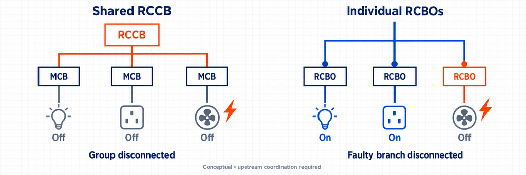
การจัดเรียงที่หนึ่งใช้ RCCB ร่วมและ MCB สาขา เครื่องทำความร้อนมีอุปกรณ์ป้องกันกระแสเกินของตัวเอง แต่ความผิดพร่องกระแสตกค้างที่เข้าเงื่อนไขก็สามารถตัดจ่ายไฟจากสาขาอื่นๆ ของโรงงานได้เช่นกัน การจัดวางเช่นนี้ขัดกับความต้องการความต่อเนื่องในการจ่ายไฟที่เจ้าของระบุไว้ หากทั้งสี่สาขาใช้ RCCB ตัวเดียวกัน.
Arrangement สองกำหนด RCBO ให้กับแต่ละวงจรปลายทางที่เหมาะสม. วิธีนี้สนับสนุนการตัดการเชื่อมต่อแบบอิสระได้ดีกว่า การคำนวณโหลดของเครื่องทำความร้อนยังคงเดิม สิ่งที่เปลี่ยนไปคือตำแหน่งที่อุปกรณ์ป้องกันกระแสตกค้างทำงาน สาขาของเครื่องจักรยังต้องปฏิบัติตามข้อกำหนดของอุปกรณ์ โดยเฉพาะหากมีไดรฟ์รวมอยู่ด้วย.
สายป้อนต้นทางอาจใช้ MCCB ได้ หากโหลด การปรับตั้ง หรือหน้าที่ในภาวะผิดพร่องสมเหตุสมผล ไม่จำเป็นต้องเป็น MCCB เพียงเพราะอาคารเรียกว่าโรงงาน และพิกัดของสายป้อนก็ไม่ได้พิสูจน์ว่าจะยังคงปิดอยู่ตลอดทุกความผิดพร่องปลายทาง.
สำหรับความต้องการความต่อเนื่องของเจ้าของนี้ ให้เลือก RCBO แยกสำหรับวงจรปลายทางที่เหมาะสม คงข้อกำหนดเฉพาะของอุปกรณ์เครื่องจักรและการประสานงานต้นทางไว้ในการออกแบบ.
มาตรฐานผลิตภัณฑ์บอกอะไร—และไม่บอกอะไร—กับคุณ
มาตรฐานระบุกรอบการทดสอบของผลิตภัณฑ์ ส่วนกฎการติดตั้งเป็นตัวกำหนดว่าจะใช้งานได้อย่างไร. หมายเลขมาตรฐานไม่ได้ให้กระแสออกแบบ กระแส fault ที่คาดหวัง หรือ arrangement วงจรสำหรับโครงการใดโครงการหนึ่ง.
อุปกรณ์สามารถมีพิกัดภายใต้มาตรฐานมากกว่าหนึ่งได้ ใช้พิกัดที่สอดคล้องกับหน้าที่ที่ใช้บังคับแทนการเลือกตัวเลข kA ที่ดูใหญ่ที่สุด การอ้างอิงแคตตาล็อก IEC ที่ส่วนท้ายระบุเอกสารที่ใช้ consulted รวมถึงฉบับปี 2024 สำหรับ IEC 60947-2, IEC 61008-1 และ IEC 61009-1.
ตรวจสอบฉบับที่ใช้บังคับหรือการรับรองระดับชาติในเอกสารผลิตภัณฑ์ สำหรับโครงการในอเมริกาเหนือ ให้ยืนยันรายการรับรองท้องถิ่นและกฎการติดตั้งที่จำเป็น การอ้างอิง IEC เพียงอย่างเดียวไม่ได้สร้างการยอมรับ.
ทำให้ส่วนที่เหลือของตู้ทำงานต่อไป
คำถามที่เหลือของระบบคือการเลือกสรร: อุปกรณ์ที่ใกล้จุดผิดพร่องที่สุดจะตัดความผิดพร่องนั้นได้หรือไม่ ในขณะที่อุปกรณ์ป้องกันต้นทางยังคงปิดอยู่? พิกัดกระแสต้นทางที่สูงกว่าไม่ได้พิสูจน์เรื่องนี้ ตรวจสอบข้อมูลการเลือกสรรของผู้ผลิตสำหรับอุปกรณ์ที่เลือกและระดับความผิดพร่อง การป้องกันสำรองเกี่ยวข้องกับความสามารถในการตัดวงจร และเป็นคำถามที่แตกต่างจากการเลือกสรร คำแนะนำการประสานงานเบรกเกอร์ อธิบายความแตกต่าง.
อุปกรณ์กระแสตกค้างที่ต่ออนุกรมกันต้องการการประเมินการประสานงานของตัวเอง รวมถึงความไว พฤติกรรมทางเวลา และความเข้ากันได้ของรูปคลื่น อุปกรณ์ 30 mA สองตัวที่เหมือนกันต่ออนุกรมกันไม่ได้สร้างการทำงานแบบ selective ใช้ คำแนะนำการประสานงาน RCD ที่ประกาศไว้ แทนการเดาจากพิกัดระบุ.
สุดท้าย การเปรียบเทียบนี้ครอบคลุมการป้องกัน overcurrent และกระแสตกค้าง การป้องกันไฟกระชากชั่วขณะมีบทบาทแยกต่างหาก อธิบายไว้ใน คู่มือ SPD ของ JUTRION. การเพิ่ม RCBO ไม่ได้ขจัดคำถามการออกแบบนั้น.
เมื่อเปรียบเทียบใบเสนอราคาตู้ไฟแผงถัดไป ให้ติดตามวงจรขาออกจากโหลดกลับไปยังแหล่งจ่าย ระบุว่าอุปกรณ์ใดตัดวงจรเมื่อเกิดความผิดพลาดแต่ละประเภท และวงจรที่ยังปกติดวงจรใดจะสูญเสียไฟเมื่ออุปกรณ์นั้นทำงาน สิ่งนี้ทำให้ความแตกต่างระหว่าง MCB, MCCB, RCCB และ RCBO เป็นรูปธรรมก่อนที่จะสั่งซื้ออุปกรณ์.
คำถามที่พบบ่อย
RCCB สามารถแทนที่ MCB ได้หรือไม่?
ไม่ได้ RCCB ตรวจจับกระแสตกค้างแต่ไม่ได้ให้การป้องกันกระแสเกินหรือกระแสลัดวงจร จำเป็นต้องมีการป้องกันกระแสเกินแยกต่างหากที่เหมาะสม RCBO รวมทั้งสองฟังก์ชันไว้ด้วยกันเมื่อพิกัดเหมาะสมกับวงจร.
MCCB ดีกว่า MCB เสมอหรือไม่?
ไม่ใช่ MCB มักเป็นตัวเลือกที่ปฏิบัติได้จริงสำหรับวงจรปลายทางขนาดเล็กกว่า MCCB มีประโยชน์เมื่อภาระงานต้องการพิกัดที่แตกต่างกัน การป้องกันที่ปรับได้ หรือฟังก์ชันควบคุมเพิ่มเติม เลือกตามวงจร ไม่ใช่ขนาดของตู้ไฟ.
ยังต้องใช้ MCB หรือไม่หากใช้ RCBO?
RCBO ที่เลือกอย่างเหมาะสมมีการป้องกันกระแสเกินและกระแสลัดวงจรของวงจรแขนงอยู่แล้ว ดังนั้นโดยปกติไม่จำเป็นต้องใช้ MCB อีกตัวเพียงเพื่อทำหน้าที่ซ้ำซ้อน การป้องกันและประสานงานของสายป้อนต้นทางยังคงมีผลบังคับใช้.
ความแตกต่างระหว่าง 63 A และ 30 mA บน RCCB คืออะไร?
63 A คือความสามารถในการรับกระแสตามพิกัดภายใต้เงื่อนไขที่ประกาศไว้ 30 mA คือกระแสตกค้างที่ทำให้ทำงานตามพิกัด ไม่มีเครื่องหมายใดให้การป้องกันกระแสเกินในตัวแก่ RCCB ซึ่งต้องใช้อุปกรณ์ป้องกันแยกต่างหาก.
RCBO แยกจะหยุดไม่ให้ทั้งบอร์ดตัดวงจรได้หรือไม่?
มันสามารถแยกความผิดพร่องกระแสตกค้างไปยังสาขาเดียว ลดการรบกวนต่อวงจรที่ปกติได้ แต่ไม่ได้ประกันว่าอุปกรณ์ป้องกันต้นทางจะยังคงปิดอยู่ ซึ่งขึ้นอยู่กับความผิดพร่องและการประสานงานของการจัดวางทั้งหมด.
เอกสารอ้างอิงทางเทคนิค
