

كيفية اختيار ATS 2P أو 3P أو 4P لأنظمة الطور الواحد والطور الثلاثي
إجابة سريعة
2P يبدّل موصلين حاملين للتيار. 3P عادةً يبدّل L1 وL2 وL3. 4P يبدّل L1 وL2 وL3 وN. يعتمد الاختيار النهائي على المصدر والحيادي والتأريض وتصميم الحماية.
ليس ATS ثنائي القطب وATS رباعي القطب نسختين مبتدئة ومتقدمة من الإجابة نفسها. يمكن أن يكونا الخيارين الصحيحين لأنظمة كهربائية مختلفة. المقارنة المفيدة هي أي الموصلات يبدّلها كل مفتاح، لا سيما الحيادي.
لإمداد طور واحد خط-ونيوترال، اختر ATS 2P مناسب عندما يجب نقل كل من L وN. لإمداد ثلاثي الطور، اختر 3P عندما يتم نقل الموصلات الثلاثة فقط، أو 4P عندما يجب نقل النيوترال أيضاً. قرار النيوترال يعتمد على تأريض المصدر وترتيبات التأريض ومتطلبات التركيب - وليس فقط على ما إذا كان مصدر النسخ الاحتياطي مولدًا أو عاكسًا. نظام الطور المنقسم 120/240 V يحتاج إلى اهتمام خاص: يمكن لمفتاح 2P مناسب نقل الموصلين الحارين مع الحفاظ على نيوترال ثابت.
بالنسبة للموزعين وبناة اللوحات، ذكر وظائف الموصلات مع عدد الأقطاب يمنع سوء التفاهم الشائع في عروض الأسعار: حيث يعرض موردان معدات “2P” مخصصة لترتيبات إمداد مختلفة.
مقارنة ATS 2P و3P و4P حسب وظيفة الموصل
القطب هو مسار موصل طاقة مبدَّل. وهو ليس مصدر طاقة، ولا طورًا بحكم التعريف، ولا وضع مفتاح. ينقل ATS ثنائي المصدر الحمل بين مصدرين سواء كان ثنائي أو ثلاثي أو رباعي الأقطاب. وبالمثل، فإن آلية I–0–II لها ثلاثة أوضاع تشغيل؛ وهذا لا يجعلها جهازًا ثلاثي الأقطاب.
تفترض المقارنة التالية تطبيق نقل AC. الأرضي الوقائي خارج ترتيب التلامس العادي لنقل المصدر.
| ترتيب التغذية والحيادي | الموصلات المبدَّلة | تكوين ATS الذي يجب فحصه | الفحص الحاسم |
|---|---|---|---|
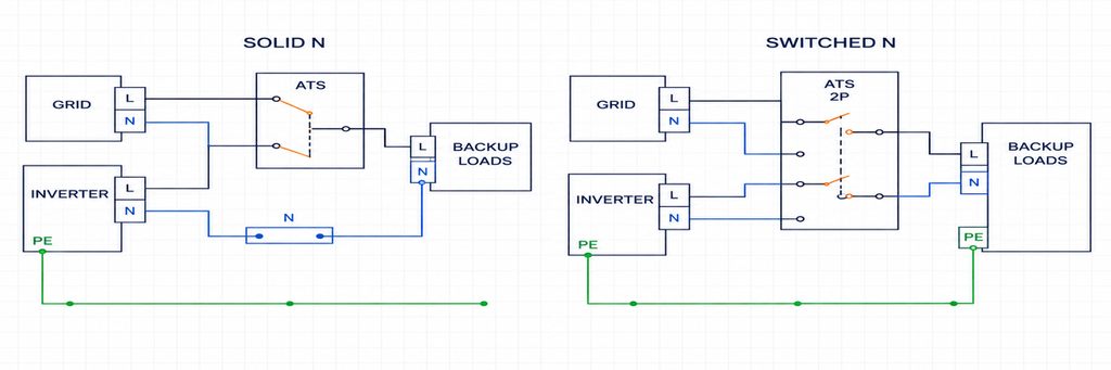
| أحادي الطور L–N، مع اشتراط تبديل الحيادي | L وN | 2P، معتمد للتحكم في الخط والمحايد | مرجع الحيادي على المصدر المختار وتسلسل التلامس |
| حمل ثلاثي الطور بدون حيادي موزَّع | L1 وL2 وL3 | 3P | يعمل الحمل ووحدة التحكم فعليًا بدون N موزَّع |
| نظام ثلاثي الطور رباعي الأسلاك مع حيادي مشترك معتمد | L1 وL2 وL3؛ يبقى N متصلًا | 3P مع توفير محايد صلب مناسب | مواقع الربط ومسارات تيار العطل في وضعي التغذية |
| نظام ثلاثي الطور رباعي الأسلاك يتطلب فصل الحيادي عن المصدر | L1 وL2 وL3 وN | 4P مع ترتيب جهة اتصال المحايد المطلوب | واجب تبديل الحيادي وتوقيته وتأريض المصدر المختار |
| 120/240 فولت طور مقسم مع محايد صلب | L1 وL2؛ يبقى N متصلًا | 2P مصنفة ومهيأة خصيصًا للطور المقسم | استشعار الجهد وتغذية التحكم وتصميم الربط المعتمد |
| 120/240 فولت طور مقسم مع محايد مفصول | L1 وL2 وN | ثلاثة مسارات مبدَّلة في تجميعة منقسمة الطور معتمدة | مخطط الشركة المصنّعة، بدلًا من افتراض طرف ثلاثي الطور عام |
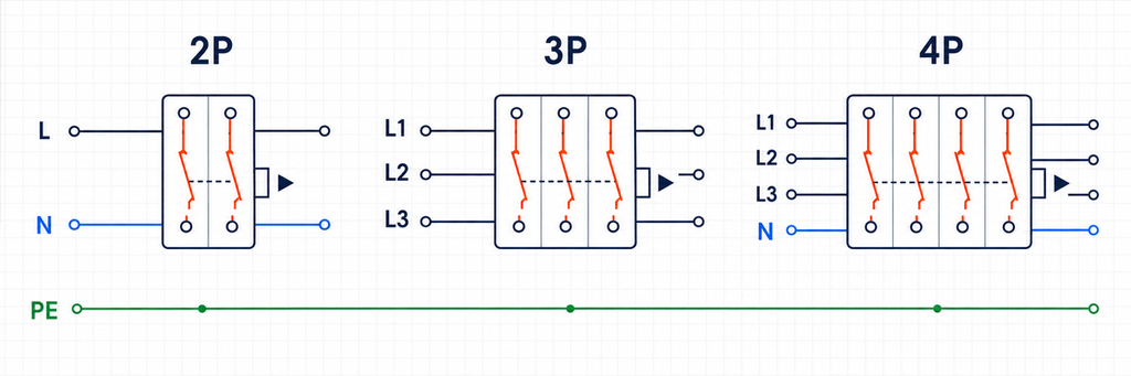
مخطط الأطراف هو مفتاح هذا الجدول: ميّز تلامسات تيار الحمل عن أي أطراف تُستخدم فقط للاستشعار أو التحكم. إنّ مبدأ تشغيل ATS ودليل الاختيار الأساسي يشرح آلية النقل الأساسية.
اختيار ATS أحادي الطور: ماذا يبدّل القطب الثاني؟
تغذية خط وحيادي
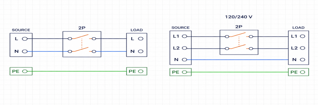
في تطبيق نموذجي 230 فولت خط إلى محايد، يستقبل الحمل موصل خط واحد ومحايد واحد. حيث يتطلب تصميم النقل فصل كلاهما عن المصدر الخارج، يوفر ATS ثنائي القطب مسارًا واحدًا للخط وآخر للمحايد.
هذه نقطة بداية عملية للعديد من اللوحات التجارية الصغيرة ولوحات الأحمال الأساسية. وليست قاعدة شاملة بأن كل تركيب أحادي الطور يجب أن يستخدم تبديل الحيادي. بعض التركيبات تبقي حياديًا مشتركًا وفق قواعد التصميم المعمول بها. يجب أن يحسم مخطط المشروع هذا التمييز قبل طلب المعدات.
بالنسبة لترتيب L–N مع تبديل الحيادي، اقرأ علامات أطراف المصدر العادي والمصدر البديل والحمل كثلاث مجموعات مترابطة. طرف الحيادي المخصص للاستشعار ليس بالضرورة طرف حيادي حمل مبدَّلًا. كما أن صورة تُظهر وحدتين لا تثبت أن كلا الموصلين ينتقلان بين المصدرين.
تغذية منقسمة الطور
مزود شمال أمريكي 120/240 فولت طور مقسم يحتوي عادة على موصلين حارين ومحايد. يمكن لمفتاح النقل المصمم لتشغيل المحايد الصلب استخدام قطبين لنقل الموصلين الحارين، مع إبقاء المحايد على اتصاله المستمر المعتمد.
لا يعني وجود قطبين بالضرورة وجود موصل ساخن واحد بالإضافة إلى محايد. بنفس القدر، لا يمكن افتراض أن منتج 230 V L–N مناسب لخدمة 120/240 V لمجرد أنه يحتوي أيضًا على قطبين. يجب أن تتطابق استشعار وحدة التحكم، وتصنيفات العزل، والإمدادات المساعدة، واعتماد المنتج مع التطبيق.
إذا كان تصميم الطور المنقسم يتطلب تبديل النيترال، فهناك حاجة إلى مسار ثالث قابل للتبديل. هذا لا يجيز توصيل مصدر طور منقسم إلى أي ATS ثلاثي الطور عادي. قد تتوقع وحدة التحكم فيه ثلاث فازات أو ترفض الإمداد كحالة فقدان طور. حدد مجموعة يدعمها المصنع للنظام الفعلي.
لا يحول أي من الترتيبين الإمداد الوارد. لا يمكن لـ ATS ذو قطبين تحويل مصدر 230 V خط إلى نيترال إلى مصدر طور منقسم 120/240 V. يجب أن يوفر المصدر البديل الفولتية وعلاقات الموصلات التي تتطلبها الأحمال المتصلة.
اختيار ATS ثلاثي الطور: وجود سلك نيترال لا يعني تلقائيًا 4P
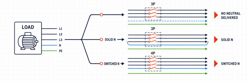
يمكن لحمل ثلاثي الطور استخدام ثلاثة موصلات خطية دون محايد موزّع، أو يمكنه أن يشكّل جزءًا من شبكة رباعية الأسلاك تغذي دوائر بين الخط والمحايد. يمكن أن يتضمن كلا الترتيبين مفتاح نقل ثلاثي القطب، ولكن لأسباب مختلفة.
لا يتم توزيع محايد إلى الحمل المنقول
بالنسبة لمغذي محرك حقيقي ثلاثي الأسلاك، يبدّل 3P كلاً من L1 وL2 وL3. لا يوجد محايد حمل ليقوم قطب رابع بتبديله. تبقى الأرضي الواقي توصيلًا واقيًا منفصلًا.
تحقق من اللوحة كاملة، وليس فقط أكبر محرك. قد يقدم دائرة تحكم، أو سخان، أو مخرج مقبس، أو جهاز مراقبة متطلب خط إلى نيترال قد يغيب عن وصف الحمل الأولي. قد يحتاج متحكم ATS أيضًا إلى نيترال لإمداده أو استشعاره، حتى عندما لا يحتاج المحرك.
يتم توزيع محايد، لكنه يبقى صلبًا
يمكن لـ ATS ثلاثي الأقطاب خدمة حمل ثلاثي الطور بأربعة أسلاك حيث يسمح التصميم بنيترال مشترك مستمر. تنقل الموصلات الثلاثة للخط؛ ويحمل النيترال عبر اتصال منفصل مصنف بشكل مناسب.
هذا ليس “نسيانًا لتبديل السلك الرابع”. إنه طوبولوجيا محايد متعمدة. تعتمد ملاءمته على كيفية ربط المصادر بالأرض وكيفية عمل حماية الأعطال. إضافة مولد دون مراجعة تلك التوصيلات القائمة يمكن أن تُبطل ترتيبًا مقبولًا لولا ذلك.
يكون هذا التمييز مهمًا بشكل خاص عندما يتغير التركيب من تكوين مولد إلى آخر. يوضح المشروع الثالث أدناه كيف يمكن لربط مصدر جديد أن يغيّر اختيار القطب الصحيح دون تغيير الحمل.
يجب أن ينتقل محايد المصدر مع الخطوط
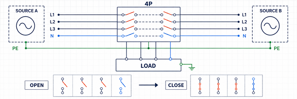
بالنسبة لتطبيق ثلاثي الطور رباعي الأسلاك يتطلب فصل محايد المصدر، ابحث في 4P. يسمح مساره المبدَّل الرابع لمحايد الحمل بأن يتبع المصدر المحدد بدلًا من أن يبقى متصلًا باستمرار بكلا محايدي المصدرين.
تحتاج كلمة "العزل" إلى الحذر هنا. لا يقوم ATS ذو نيترال قابل للتبديل بفصل شبكة التأريض الوقائي، ولا يثبت عدد الأقطاب بمفرده ملاءمته كعازل للصيانة. يمكن أن تظل الاتصالات الأخرى، بما في ذلك الأسلاك التجاوزية، ذات صلة. وصف الوظيفة الفعلية كتبديل مصدر-نيترال بدلاً من الوعد بفصل كهربائي كامل لكل ما هو متصل بالموقع.
ثلاثة مشاريع، ثلاثة قرارات مختلفة للأقطاب
الأمثلة التالية هي ملخصات هندسية توضيحية، وليست تركيبات عملاء JUTRION. يُفترض أن المتطلبات الحالية قد حُددت بشكل منفصل. يعزل كل مثال القرار الذي يحدد الموصلات المبدَّلة.
المشروع 1: لوحة أحمال أساسية 230 V — اختر 2P للخط والنيترال
يحتاج مبنى تجاري صغير إلى نسخ احتياطي للإضاءة والاتصالات ودائرة التبريد. يوفر كلا المصدرين 230 V خط إلى نيترال عند 50 هرتز. تحتوي لوحة الأحمال الأساسية على طلب تصميم موثق 40 A؛ وATS المقترح هو مرشح 63 A مع درجة تشغيل مناسبة. يتطلب تصميم التركيب نقل خط اللوحة والنيترال بين المصدرين.
قرار الأقطاب هو 2P، لتبديل الخط والمحايد. تحدد ترتيبات التأريض من جهة المصدر المرجع المناسب لكل وضع تشغيل. لا يُترك محايد الحمل مرتبطًا بالمصدر غير النشط عبر توصيل ثانٍ.
تتمثل مشكلة التنفيذ الرئيسية في حدود لوحة الأحمال الأساسية. نقل مغذيات الخط إلى النسخ الاحتياطي مع ترك محايداتها على قضيب محايد غير ذي صلة في اللوحة الرئيسية يُبطل الفصل المقصود. يجب أن تنتمي الموصلات المرتبطة بكل دائرة منقولة إلى نفس ترتيب النسخ الاحتياطي المصمم.
بالنسبة لباني اللوحات، يعني هذا أنه يجب النظر في ATS مدمج وغلاف الأحمال الأساسية معًا. ليست المهمة مجرد تركيب مفتاح بجانب صف القواطع الموجود؛ يجب أن يكون هناك مساحة لموصلات الدائرة الخارجة، ونهايات النيترال، والأجهزة الوقائية.
رقم 63 A لا يحدد الأقطاب، وهذا المثال لا يثبت هامش حجم عالمي. قد يغير طلب موثق أصغر أو أكبر تصنيف التيار مع بقاء قرار نقل L–N دون تغيير.
المشروع 2: لوحة مضخة ثلاثية الأسلاك 400 V — اختر 3P
تأخذ لوحة المضخة إمداد ثلاثي الطور 400 V، 50 هرتز من المرافق أو المولد. تستخدم محركاتها طاقة خط إلى خط. يوفر محول تحكم، متصل عبر خطين على الجانب المنقول، تحكمات اللوحة. لا توجد أحمال خط إلى نيترال أو نيترال إمداد موزع. يدعم متحكم ATS المحدد ترتيب الأسلاك الثلاثة.
قرار الأقطاب هو 3P، لتبديل L1 وL2 وL3. لا يوجد محايد حمل لتخصيصه لملامس رابع. ترتيب الملف الثانوي لمحوّل التحكم هو تفصيل تصميمي منفصل؛ ولا يخلق حاجة لتوزيع محايد المصدر الوارد.
هنا يكون الفحص الإضافي المهم هو تسلسل الأطوار. يجب أن يحافظ تعريف الأطراف الصادرة على علاقة الأطوار المقصودة على أي من المصدرين. النقل الميكانيكي الناجح ليس دليلاً كافياً على أن المحركات ستعمل في الاتجاه المقصود. توافق المصدر والتشغيل التجريبي من مسؤولية personnel مؤهلين باستخدام إجراء الاختبار المعتمد.
قد يغير مأخذ خدمة 230 فولت المستقبلي موجز المتطلبات إذا احتاج إلى محايد في التغذية. يمكن للمصمم توفير دائرة مناسبة يتم تغذيتها بشكل منفصل أو محولة، أو مراجعة ترتيب التوزيع. شراء 4P اليوم لا يوفر المحايد المفقود بحد ذاته ولا يحسم تصميم التأريض المستقبلي.
هذا حد تكلفة مفيد: اشترِ الوظائف التي تحتاجها اللوحة الكاملة. لا يمكن لملامس غير مستخدم أن يحل محل تغذية التحكم الصحيحة أو واجب تبديل المحرك أو مراقبة المصدر.
المشروع 3: لوحة تجارية 208/120 فولت — يمكن لتغيير المصدر أن يحول الاختيار من 3P إلى 4P
اعتبر لوحة ثلاثية الطور بأربعة أسلاك في أمريكا الشمالية تغذي معدات خط إلى خط ودارات 120 فولت. يستخدم التصميم الاحتياطي الأصلي محايدًا مشتركًا مستمرًا، مع مرجع النظام عند الخدمة ولا يوجد ربط محايد مولد إلى الإطار في هذا التكوين المعتمد. يقوم ATS ثلاثي الأقطاب بنقل الموصلات الحارة الثلاثة.
يقترح المالك الآن ترتيب مولد مختلف يحتفظ بربط النيوترال بالأرض الخاص به ويعمل كمصدر مشتق بشكل منفصل. الحفاظ على وصلة النيوترال المشترك القديمة سيجمع كلا نظامي النيوترال بينما يربط الربط الوقائي أيضاً المعدات. يمكن لتيار النيوترال الطبيعي حينئذ أن ينقسم بين مسارات متوازية غير مقصودة.
بالنسبة للتصميم المعدّل الذي يتطلب فصل نيوترال المصدر، اختر ترتيب 4P مناسباً. يتبع مسار النيوترال الخاص به المصدر المحدد: مرجع الخدمة أثناء تشغيل المرافق، ومرجع جانب المولد أثناء تشغيل الاحتياط. يتم الحفاظ على استمرارية الأرضي الوقائي بدلاً من تبديله بعيداً.
يجب على مصمم المشروع أيضاً تنسيق استشعار عطل الأرض وأي مسار تجاوز مع ذلك الترتيب المعدّل. تغيير القطب جزء واحد من إعادة التصميم، وليس موافقة تلقائية على التركيب بأكمله. تعديل ربط المولد لمجرد الحفاظ على ATS القديم ليس اختصار شراء مقبولاً.
التمييز العملي عن المشروع 2 واضح: هذه اللوحة توزع النيوترال، وتصميم المصدر الجديد يتطلب فصله. لا نوع المبنى ولا زيادة الأمبيرات هي ما يستدعي القطب الرابع.
تشير هذه المشاريع الثلاثة أيضًا إلى تنسيقات منتجات مختلفة. قد تبدأ لوحة حمل أساسية مدمجة 230 فولت بـ ATS على سكة DIN، بينما قد تحتاج مشاريع المضخة ثلاثية الطور واللوحة التجارية إلى عائلة صناعية من فئة PC أو CB. تقدم JUTRION هذه التنسيقات في مجموعة مفاتيح النقل التلقائي. لا تزال ظروف المشروع تحدد القطب المطلوب وتكوين وحدة التحكم.
يجب أن يعمل تبديل النيوترال والتأريض وتوقيت الملامسات معاً
حافظ على النيوترال والأرضي الوقائي كوظيفتين منفصلتين
يحمل النيوترال تيار الحمل الطبيعي؛ ويوفر الأرضي الوقائي مسار عطل. لذلك، فإن الموصل الوقائي والنيوترال المدمج، أو PEN، ليس نيوترالاً عادياً يمكن وضعه على قطب ATS احتياطي. يجب على مصمم التركيب تحديد أين تنفصل وظائف PEN وأين يتم إرجاع كل مصدر إلى الأرض.
الاختبار العملي بسيط: حدد مسار العودة المقصود لتيار الحمل الطبيعي، ثم حدد مسار العطل على كل مصدر. يمكن لوصلات النيوترال غير المقصودة أن تتجاوز استشعار التيار المتبقي أو تنشئ مسارات تيار متوازية. لا يمكن لقطب رابع إصلاح ربط غير صحيح أو نيوترال مستعار أو جهاز وقائي في غير موضعه.
بالنسبة لتركيبات سكنية بريطانية مدعومة بالعاكس، فإن IET إرشادات حول الفصل التلقائي في وضع الجزيرة يربط بين تأريض النظام ومعدات الجزيرة والحماية من التيار المتبقي. يشرح لماذا يجب أن يعمل موقع المرجع وجهاز الحماية معًا عندما يكون تيار عطل العاكس محدودًا. هذه مسألة تصميم نظام، وليست وعدًا يوفره تصنيف “4P.”
وبالتالي هناك خياران منفصلان للمنتج: ترتيب موصلات ATS وجهاز التيار المتبقي المناسب للمصدر والحمل. ال دليل اختيار RCBO يتناول الأخير. لا تستخدم أقطاب ATS إضافية كبديل عن اختيار وتنسيق الحماية المطلوبة.
تحقق من متى يفتح ويغلق المحايد
يمكن لمفتاحي نقل رباعيي الأقطاب تشغيل نقاط اتصال المحايد الخاصة بهما بشكل مختلف. يؤكد عدد الأقطاب وجود مسار تبديل للمحايد؛ لكنه لا يصف توقيته.
ميّز بين محايد متصل باستمرار، ومحايد ينفصل أثناء النقل، وترتيب محايد متداخل عمدًا. نقاط اتصال المحايد المتداخلة تربط محايدات المصدر لحظيًا؛ وهذا ليس نفس توصيل موصلات خط المصدر على التوازي. إنه خيار هندسي محدد، وليس وصلة تُضاف أثناء التركيب.
توقيت المحايد بالنسبة للخطوط مسألة أخرى. “إغلاق مبكر، فتح متأخر” يصف كيفية ارتباط نقطة اتصال المحايد بنقاط اتصال الخطوط؛ وهو لا يعني بالضرورة تداخل محايدي المصدر. استخدم تسلسل نقاط الاتصال من الشركة المصنعة بدلًا من تفسير عبارة قصيرة في الكتالوج بمفردها.
بالنسبة لإمداد بأحمال خط إلى محايد، قد يؤدي فتح المحايد غير المقصود أثناء بقاء الخطوط مُكهربة إلى اضطراب جهود الأحمال. الحل هو آلية نقل منسّقة—وليس تبديلًا مستقلًا للمحايد بمرحّل غير مرتبط.
شرح IET لتأريض وضع الجزيرة يوضح العلاقة بين نقاط اتصال الخطوط ونقاط اتصال المحايد ومرجع الجزيرة. إنه إرشاد بريطاني من 2021، مفيد لفهم المبدأ؛ ويجب أن يستخدم تصميم التركيب الحالي القواعد والتعليمات المعمول بها للمعدات.
هناك أيضًا حدود للمعايير. النطاق المنشور لـ IEC 60947-6-1:2026 يستبعد TSE ذا المحايد المتداخل من تغطية تلك الطبعة. لا تفترض أن كل خيار محايد مشمول بتصنيف معيار مألوف من جهة أخرى.
بالنسبة لعاكس هجين، حدد من يتحكم في المحايد
ابدأ بمخطط النسخ الاحتياطي المعتمد للعاكس. حدد ما إذا كان يحتوي بالفعل على وظيفة نقل وأي جهاز ينشئ مرجع المحايد للجزيرة. استخدام ATS خارجي كتجاوز للصيانة له وظيفة مختلفة عن الجهاز الذي يفصل التركيب عن الشبكة.
يمكن أن يُدخل دخل الشبكة ومخرج النسخ الاحتياطي والتجاوز أكثر من مسار واحد إلى المحايد نفسه. قد يفصل مفتاح 4P المقترح مسارًا واحدًا بينما يبقى آخر متصلًا في مكان آخر. وبالعكس، قد يتعارض قطع خارجي غير ضروري للمحايد مع ترتيب داخلي مقصود.
القرار ليس “الطاقة الشمسية تعني 4P.” يجب أن تتطابق مسارات الشبكة والنسخ الاحتياطي والتجاوز مع التصميم المدعوم للعاكس. لهذا يكون طراز العاكس ومخططه أحادي الخط مفيدين في مرحلة عرض السعر.
كما لا يصبح مفتاح النقل AC جهاز تبديل PV DC لمجرد تركيبه في مشروع شمسي. أبقِ ATS على جانب AC المحدد لاستخدامه. حماية وإ isolation لمصفوفة DC تطبيقات منفصلة.
تحقق من سعة المحايد ومساحة اللوحة قبل مقارنة الأسعار
اتصال المحايد له واجب تيار حتى عندما لا يحتوي على نقاط اتصال تبديل. بالنسبة لـ 3P مع محايد صلب، حدد قضيب المحايد أو مجموعة الأطراف التي ستحمل تيار العودة. بالنسبة لـ 4P، حدد نقطة اتصال المحايد المقدرة وأطرافها. لا ينبغي اختيار أي منهما بناءً على مظهر أقطاب الخط فقط.
في دائرة أحادية الطور L–N، يحمل المحايد عادةً نفس تيار الحمل الذي يحمله الخط. إنه ليس اتصال ملحق خفيف الحمل. في لوحة ثلاثية الطور، يعتمد تيار المحايد على نمط الحمل المتصل؛ ولا ينبغي افتراض أنه ضئيل لمجرد أن الإمداد ثلاثي الطور.
قد يبقى المحايد ضروريًا حتى عندما تنتج حالة تشغيل معينة تيارًا ضئيلًا فيه. على سبيل المثال، قد تعمل أحمال خط إلى محايد موزعة بالتساوي لاحقًا في أوقات مختلفة. إيقاف تشغيل المعدات على طورين لا يزيل متطلب تيار العودة للمعدات التي لا تزال تعمل على الطور الثالث.
يستحق تخطيط اللوحة فحصًا ملموسًا بالقدر نفسه. قارن عرض المفتاح المعروض ومراكز التركيب واتجاه دخول الكابل ومواضع الأطراف بالمساحة المتاحة. ضمّن أحجام الموصلات المسموح بها من الشركة المصنعة وخلوص الانحناء، بدلًا من مقارنة أبعاد الجسم المعدني فقط.
في مشروع استبدال، قد يتطلب مسار المحايد الإضافي تمديد كابل لم يوفره الصندوق الحالي قط. قد لا يصل كابل يصل إلى قضيب المحايد الصلب القديم إلى طرف محايد مبدّل جديد دون تعديل. كما تحتاج دعامة الكابل وتحميل الأطراف إلى اهتمام؛ فلا ينبغي أن يصبح المفتاح دعامة لموصل مشدود.
بالنسبة للموزعين الذين يخزّون تجميعات ATS المغلقة، حدد ما إذا كان النطاق المسعّر يشمل أطراف المحايد وقضيب أرضي واقٍ منفصل وملحقات التوصيل المطلوبة. آلية نقل عارية وصندوق جاهز للتوصيل عرضان مختلفان حتى عندما يتطابق التيار الرئيسي وعدد الأقطاب.
توضح هذه التفاصيل فرق سعر حقيقي. وهي أكثر فائدة من افتراض علاوة نسبة ثابتة لـ 4P أو اختيار أصغر صندوق في الكتالوج.
حوّل ترتيب الأقطاب الصحيح إلى خيار منتج قابل للاستخدام
بعد اختيار ترتيب الموصلات، قارن صيغة التركيب وبنية التبديل. تقدم JUTRION الطراز JR2-63 كسلسلة DIN-rail وتعرض JUQ5 وJUKG7 ضمن عائلات فئة PC. يجب أن يظل المتغير المطلوب مطابقاً لتكوين الأقطاب والتقديرات الكهربائية المحددة أعلاه.
للوحة أحمال أساسية مدمجة، ابدأ بصيغة DIN-rail. قارن ترتيب الموصلات المدعوم فيها مع المشروع 1، ثم حدد ما إذا كانت حمولة التيار ومساحة التوصيل مناسبتين للوحة. اسم السلسلة وحده ليس نتيجة اختيار.
للوحة ذات حماية منبعية منسقة بشكل منفصل، قارن عائلات فئة PC. أبقِ قرار المحايد منفصلاً عن بنية الحماية: PC مقابل CB يصف جانباً مختلفاً من المعدات عن 3P مقابل 4P. حيثما كانت هناك حاجة إلى مجموعة نقل قائمة على القاطع، ناقش ترتيب فئة CB بدلاً من التعامل مع قطب آخر كوظيفة حماية أخرى.
| تم تحديده بالفعل | لا يزال يتعين التحقق من الطراز المعروض | لماذا يمكن أن يغير الطلب |
|---|---|---|
| ترتيب موصلات 2P أو 3P أو 4P | وظائف الأطراف، وتوفير المحايد، ونظام المصدر المدعوم | نفس عدد الأقطاب يمكن أن يخدم موصلات مختلفة |
| تيار الحمل المطلوب | تيار التشغيل عند الجهد المذكور وظروف التشغيل والتركيب | تعيين الإطار وحده غير كافٍ |
| محايد مبدل مطلوب | تصنيف تيار المحايد وتسلسل التلامس | لا ينبغي تخمين سعة المحايد ولا التوقيت |
| المصادر العادية والبديلة محددة | الاستشعار والتردد ومصدر التحكم وواجهة المولد | وحدة مناسبة ميكانيكياً قد تحتوي على عناصر تحكم غير متوافقة |
| تصميم حماية المشروع مُعتمد | أداء الأعطال المحدد وتنسيق الجهاز الأعلى | المزيد من الأقطاب لا يزيد تصنيف العطل تلقائياً |
احتفظ بحساب السعة منفصلاً. إذا لم يتم تحديد التيار المطلوب بعد، استخدم دليل تحجيم ATS لتيار الحمل وقدرة المولد بالكيلوفولت أمبير. إضافة قطب محايد لا يزيد من مقدار التيار الذي يمكن لكل قطب خط حمله.
بالنسبة للطلبات المتكررة، احتفظ بوصف المتغير الكامل مع الرسم المعتمد. الطلب اللاحق الذي ينسخ فقط اسم العائلة وتصنيف الأمبير يمكن أن يفقد جهد وحدة التحكم الأصلي أو خيار المحايد أو نطاق الحاوية. تسجيل تلك الخيارات مرة واحدة يجعل الشراء المتكرر أكثر موثوقية دون تحويل كل طلب إلى تمرين تصميم جديد.
الشهادة تنتمي أيضاً إلى المعدات المحددة بالضبط. تحدد UL Solutions معيار UL 1008 لتقييم مفتاح النقل في تطبيقات الطوارئ ذات الصلة والاحتياطي الاختياري. لا “4P” ولا بيان المعايير العام يثبت إدراج أو قبول طراز JUTRION معين لمشروع ما. احصل على دليل الطراز المعمول به حيثما كان مطلوباً.
أسئلة يطرحها المشترون حول أقطاب ATS
هل ATS رباعي الأقطاب دائمًا أكثر أمانًا من ATS ثلاثي الأقطاب؟
لا. استخدم 4P عندما يتطلب التصميم تبديل المحايد؛ استخدم 3P حيث يُطلب ترتيب محايد صلب معتمد. الأمان يأتي من تصميم المصدر والتأريض والحماية الكامل.
هل يمكن لـ ATS ثنائي الأقطاب تغذية نظام طور مقسم 120/240 فولت؟
نعم، إذا كان مصمماً لنقل كلا الموصلين الحاملين للتيار مع محايد صلب. طراز 2P خط ومحايد ليس مناسباً تلقائياً؛ الطور المشقوق ذو المحايد المبدل يتطلب مسار تبديل ثالث.
هل يمكنني استخدام ATS رباعي الأقطاب على تغذية أحادية الطور؟
فقط عندما تكون تلك التهيئة مدعومة من الشركة المصنعة. جهات الاتصال الاحتياطية لا تثبت أن دائرة الاستشعار أو وحدة التحكم أو تخصيص الأطراف سيعمل مع مصدر أحادي الطور.
هل يعني 3P+N نفس معنى 4P؟
ليس بشكل موثوق. قد يصف “3P+N” ثلاثة خطوط مبدلة بالإضافة إلى توفير محايد صلب. تأكد مما إذا كان N جهة اتصال مبدلة على مخطط المنتج.
هل يمكنني تحويل ATS ثلاثي الأقطاب موجود إلى رباعي الأقطاب؟
فقط من خلال تحويل معتمد لذلك التجميع المحدد، إذا كان متاحًا. لا يحول المرحل المحايد المضاف الآلية الأصلية إلى ATS رباعي الأقطاب منسق.
هل يبدل ATS موصل الأرضي؟
لا. الأرضي الواقي خارج جهات اتصال النقل العادية 2P أو 3P أو 4P. لا تعامل PE أو PEN القادم كموصل محايد احتياطي.
هل تحتاج لمطابقة ATS مع لوحتك؟
أرسل إلى JUTRION مخطط المصدر والحمل، وجهد النظام وتردده، والتيار المطلوب، وما إذا كان محايد الحمل سيبقى صلباً أو سيتم تبديله. أدرج طراز المولد أو العاكس عندما يؤثر على ذلك القرار. هذه التفاصيل تسمح للنقاش بالانتقال من “2P أم 4P؟” إلى تهيئة منتج محددة.
اتصل بـ JUTRION بخصوص تطبيق ATS الخاص بك مع تلك المتطلبات. إذا لم يتم تصميم ترتيب المحايد بعد، ضع علامة عليه كغير محلول بدلاً من السماح لعرض السعر بتحديد نظام التأريض.
المراجع الفنية
