

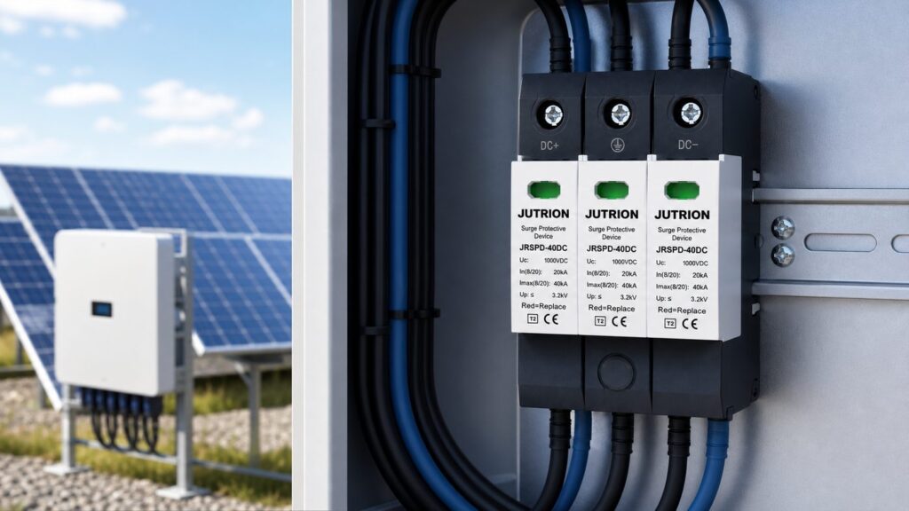
ຄຳຕອບໄວ: ວິທີກຳນົດ SPD ກະແສຕົງສຳລັບແຜງໂຊລາ
ເລືອກ SPD ກະແສຕົງໂດຍສີ່ຂໍ້ມູນ: ແຮງດັນວົງຈອນເປີດສູງສຸດຂອງແຜງ, ກະແສລັດວົງຈອນສູງສຸດ, ວ່າມີລະບົບປ້ອງກັນຟ້າຜ່າຫຼືບໍ່, ແລະການຈັດວາງສາຍດິນ. ກຳນົດແຮງດັນປະຕິບັດການຕໍ່ເນື່ອງສູງສຸດໃຫ້ Ucpv ≥ 1.2 × Voc ສູງສຸດຂອງແຜງ (IEC 61643-32), ເລືອກ ປະເພດ 2 ສຳລັບຫຼັງຄາທົ່ວໄປ ຫຼື ປະເພດ 1+2 ເມື່ອມີຄວາມສ່ຽງຟ້າຜ່າຫຼືມີ LPS, ແລະຢືນຢັນວ່າອຸປະກອນໄດ້ຮັບການຈັດອັນດັບສຳລັບກະແສຕົງພ້ອມມີຕົວຕັດຄວາມຮ້ອນໃນຕົວ. ຈັບຄູ່ຊັ້ນແຮງດັນກັບລະບົບ: 600 V, 1000 V, ຫຼື 1500 V.
ອຸປະກອນປ້ອງກັນແຮງດັນເກີນກະແສຕົງເສຍຫາຍໃນແບບທີ່ອຸປະກອນກະແສສະຫຼັບບໍ່ເຄີຍເປັນ. ໃນຕອນເຊົ້າທີ່ໜາວແລະແຈ້ງ ສາຍແຜງໂຊລາຢູ່ທີ່ແຮງດັນສູງສຸດຂອງປີ, ແຜງມີກະແສໄຟຟ້າທັນທີທີ່ແສງຕາເວັນຂຶ້ນພົ້ນຂອບຟ້າ, ແລະບໍ່ມີຈຸດສູນສະຫຼັບເພື່ອຊ່ວຍດັບອາກໄຟຟ້າພາຍໃນ. SPD ທີ່ເລືອກຕາມແຮງດັນລະບົບທີ່ກຳນົດ — “ມັນເປັນລະບົບ 1000 V, ດັ່ງນັ້ນອຸປະກອນ 1000 V ກໍໃຊ້ໄດ້” — ສາມາດຢູ່ໃນສະພາບເກີນກຳລັງຕະຫຼອດເວລາ, ຄ່ອຍໆຮົ່ວໄຫຼ, ແລະຕັດຕົວຕັດຄວາມຮ້ອນກ່ອນອາຍຸການທີ່ກຳນົດໄວ້ຫຼາຍເດືອນ. ຕົວເລກທີ່ປົກປ້ອງແຜງບໍ່ແມ່ນແຮງດັນທີ່ກຳນົດ; ມັນແມ່ນແຮງດັນວົງຈອນເປີດສູງສຸດຕົວຈິງຂອງແຜງບວກກັບສ່ວນເຜື່ອ, ແລະທຸກຢ່າງອື່ນໃນຂໍ້ກຳນົດກໍຕາມມາຈາກການໄດ້ຕົວເລກນັ້ນຢ່າງຖືກຕ້ອງ.
ຄູ່ມືນີ້ນຳພາຜ່ານການເລືອກດ້ານ DC ແບບທີ່ຜູ້ສ້າງຕູ້ແຜງ ຫຼື ຜູ້ກຳນົດສະເປັກ EPC ເຮັດຕົວຈິງ: ກຳນົດອິນພຸດຂອງແຜງ, ກຳນົດຂະໜາດແຮງດັນ, ເລືອກປະເພດ, ຕັ້ງຄ່າພິກັດການປ້ອງກັນ, ຈາກນັ້ນປິດວົງຈອນກ່ຽວກັບກະແສຟອລຕ໌, ຕົວຕັດວົງຈອນຄວາມຮ້ອນ, ການຈັດຮູບແບບ, ການຕໍ່ດິນ, ເອກະສານຂໍ້ມູນ, ດ້ານ AC, ແລະ ວົງຈອນຊີວິດ. ມັນປະຕິບັດຕາມກອບຂອງ IEC 61643-31 (ມາດຕະຖານຜະລິດຕະພັນສຳລັບ SPD DC ຂອງ PV) ແລະ IEC 61643-32 (ການເລືອກ ແລະ ການນຳໃຊ້). ສຳລັບມຸມມອງທີ່ກວ້າງກວ່າໃນທົ່ວອຸປະກອນປະເພດ 1, 2, ແລະ 3 ແລະ ທັງດ້ານ AC ແລະ DC, ເບິ່ງ ຄູ່ມືອຸປະກອນປ້ອງກັນແຮງດັນເກີນຄົບຊຸດ; ບົດຄວາມນີ້ແມ່ນຄູ່ຄຽງດ້ານ DC ທີ່ລົງເລິກໃນຈຸດທີ່ແຜງໂຊລາເຮັດໃຫ້ການຕັດສິນໃຈແຕກຕ່າງ.
ເປັນຫຍັງ SPD DC ຈຶ່ງບໍ່ແມ່ນ SPD AC ທີ່ຫັນຂ້າງ
ການລໍ້ໃຈໃຫ້ເອົາຕົວກັນແຮງດັນເກີນ AC ທີ່ເຫຼືອມາໃຊ້ກັບດ້ານ PV ແມ່ນທາງລັດທີ່ອັນຕະລາຍທີ່ສຸດໃນການປ້ອງກັນແຮງດັນເກີນຂອງໂຊລາ. ກະແສສະຫຼັບຜ່ານສູນໜຶ່ງຮ້ອຍເທື່ອຕໍ່ວິນາທີ; ເມື່ອວາຣິສເຕີທີ່ໃກ້ໝົດອາຍຸເລີ່ມນຳກະແສ, ຈຸດສູນກະແສທຳມະຊາດນັ້ນຊ່ວຍໃຫ້ຕົວຕັດວົງຈອນພາຍໃນຕັດກະແສຕາມຫຼັງໄດ້. ແຜງໂຟໂຕໂວນຕາອິກຈ່າຍກະແສກົງຢ່າງຕໍ່ເນື່ອງໂດຍບໍ່ມີຈຸດຕັດສູນເລີຍ. ດັ່ງນັ້ນ ວາຣິສເຕີໂລຫະອອກໄຊທີ່ເສື່ອມສະພາບຈຶ່ງສາມາດຮັກສາອາກ DC ໄວ້, ຮ້ອນຂຶ້ນ, ແລະ ກາຍເປັນແຫຼ່ງໄຟໄໝ້ແທນທີ່ຈະລົ້ມເຫຼວແບບປອດໄພ.
ອົງປະກອບປ້ອງກັນເອງເຮັດວຽກແບບດຽວກັນໃນທັງສອງໂລກ: ຕົວຕ້ານການປ່ຽນແປງແຮງດັນແບບໂລຫະອອກໄຊ (MOV) ໂດຍພື້ນຖານແລ້ວເປັນວົງຈອນເປີດຢູ່ທີ່ແຮງດັນປົກກະຕິ ແລະຈະຫຼຸດລົງເປັນອິມພີແດນຕໍ່າພາຍໃນນາໂນວິນາທີ ເມື່ອແຮງດັນຂ້າມຜ່ານຈຸດເລີ່ມຕົ້ນຂອງມັນ, ຫັນເຫກະແສກະທົບລົງດິນ ແລະຈຳກັດແຮງດັນທີ່ຜ່ານໄປ. ບາງອຸປະກອນຈັບຄູ່ MOV ກັບທໍ່ລະບາຍອາຍແກັສ (GDT) ແບບອະນຸກົມ ເພື່ອກຳຈັດກະແສຮົ່ວໄຫຼ ແລະປັບປຸງຮູບແບບການລົ້ມເຫຼວ. ສິ່ງທີ່ປ່ຽນແປງຢູ່ຝັ່ງ DC ບໍ່ແມ່ນຟີຊິກສາດຂອງການຈຳກັດແຮງດັນ ແຕ່ແມ່ນພຶດຕິກຳຄວາມຜິດພາຍຫຼັງທີ່ອົງປະກອບເສື່ອມສະພາບ, ແລະນັ້ນຄືເຫດຜົນທີ່ອຸປະກອນທັງໝົດ — ອັດຕາແຮງດັນຂອງມັນ, ຕົວຕັດວົງຈອນຂອງມັນ, ແລະໂຄງສ້າງພາຍໃນຂອງມັນ — ຖືກສ້າງຂຶ້ນສຳລັບ DC.
ດ້ວຍເຫດຜົນນັ້ນ SPD DC ຂອງ PV ທີ່ໄດ້ມາດຕະຖານຈຶ່ງຖືກສ້າງຂຶ້ນຕ່າງກັນ. ມັນຖືກຈັດອັນດັບສຳລັບການເຮັດວຽກ DC ຢ່າງຕໍ່ເນື່ອງ, ຮູບແບບການປ້ອງກັນຂອງມັນຖືກຈັດວາງສຳລັບລະບົບ DC ແບບລອຍຕົວ ຫຼືຕໍ່ດິນຕາມໜ້າທີ່ ແທນທີ່ຈະເປັນແຫຼ່ງຈ່າຍ AC ທີ່ອ້າງອີງນິວຕຣອນ, ແລະມັນມີ ຕົວຕັດວົງຈອນຄວາມຮ້ອນໃນຕົວ ທີ່ແຍກຕົວຕ້ານການປ່ຽນແປງແຮງດັນອອກເມື່ອເກີດຄວາມລົ້ມເຫຼວ ໂດຍບໍ່ຕ້ອງອາໄສຈຸດສູນກະແສ. IEC 61643-31 ລະບຸຢ່າງຊັດເຈນວ່າອຸປະກອນເຫຼົ່ານີ້ແມ່ນສະເພາະສຳລັບຝັ່ງ DC ຂອງເຄື່ອງກຳເນີດ PV ແລະອິນເວີຣ໌ເຕີ — SPD AC ບໍ່ຕອບສະໜອງຂໍ້ກຳນົດເຫຼົ່ານັ້ນ ແລະຕ້ອງບໍ່ນຳມາໃຊ້ແທນເດັດຂາດ. ນີ້ແມ່ນວຽກທີ່ແຕກຕ່າງຈາກອຸປະກອນທີ່ປ້ອງກັນແຮງດັນເກີນ ແລະແຮງດັນຕໍ່າແບບຕໍ່ເນື່ອງຂອງໄຟຟ້າຫຼັກ; ຖ້າຄວາມກັງວົນຂອງທ່ານແມ່ນການເພີ່ມຂຶ້ນຊ້າໆ ຫຼືການຫຼຸດລົງຂອງແຮງດັນຈ່າຍ ແທນທີ່ຈະເປັນກະແສກະທົບຊົ່ວຄາວໃນລະດັບໄມໂຄຣວິນາທີ, ນັ້ນແມ່ນຂອບເຂດຂອງ ຕົວປ້ອງກັນແຮງດັນເກີນ ແລະແຮງດັນຕໍ່າ, ບໍ່ແມ່ນ SPD.
ເລີ່ມຕົ້ນດ້ວຍແຜງໂຊລາ: ສີ່ຂໍ້ມູນປ້ອນທີ່ຕັດສິນ SPD
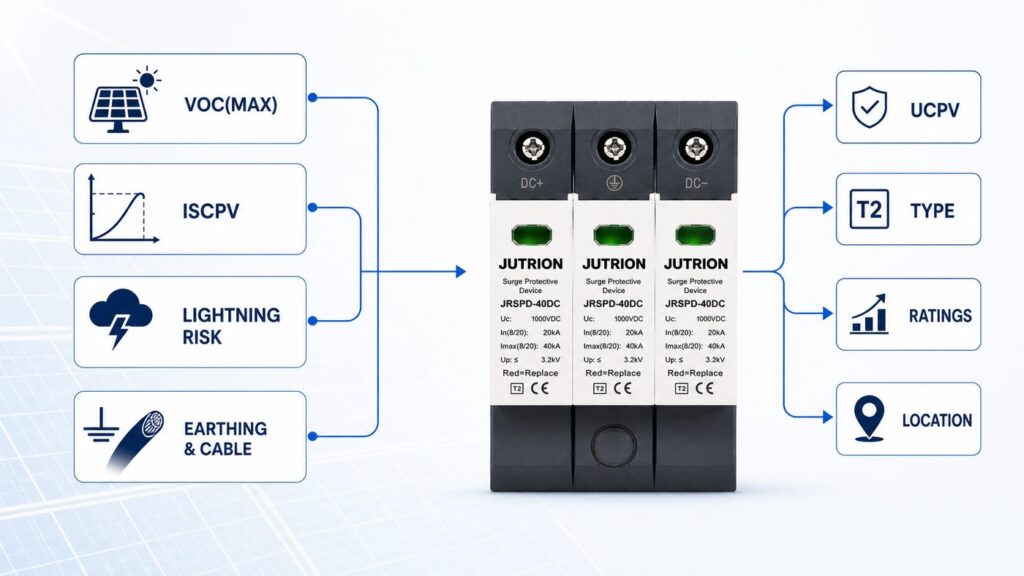
ທຸກໆອັດຕາທີ່ຢູ່ໃນເອກະສານຂໍ້ມູນ SPD ຕອບຄຳຖາມກ່ຽວກັບແຜງໂຊລາ. ກຳນົດສີ່ຂໍ້ມູນປ້ອນເຫຼົ່ານີ້ກ່ອນທີ່ທ່ານຈະເບິ່ງຜະລິດຕະພັນໃດໆ:
- ແຮງດັນວົງຈອນເປີດສູງສຸດ, Uoc(max). ບໍ່ແມ່ນແຮງດັນລະບົບທີ່ກຳນົດໄວ້ — ແມ່ນແຮງດັນສູງສຸດທີ່ສາຍສະຕຣິງສາມາດຂຶ້ນເຖິງໄດ້, ເຊິ່ງເກີດຂຶ້ນຢູ່ສະພາບວົງຈອນເປີດໃນຕອນເຊົ້າທີ່ໜາວທີ່ສຸດທີ່ຄາດວ່າຈະເກີດຂຶ້ນ. ຄ່ານີ້ກຳນົດ Ucpv.
- ກະແສລັດວົງຈອນສູງສຸດ, Iscpv. ກະແສລັດວົງຈອນທີ່ຄາດວ່າຈະເກີດຂຶ້ນຂອງອາເຣຢູ່ຕຳແໜ່ງຂອງ SPD, ເພີ່ມຂຶ້ນສຳລັບຄວາມເຂັ້ມແສງ ແລະ ອຸນຫະພູມ. ຄ່ານີ້ກຳນົດຄວາມສາມາດໃນການທົນຕໍ່ກະແສລັດວົງຈອນ ແລະ ຕັດສິນວ່າຈຳເປັນຕ້ອງມີອຸປະກອນສຳຮອງພາຍນອກຫຼືບໍ່.
- ການສຳຜັດກັບຟ້າຜ່າ ແລະ ການມີລະບົບປ້ອງກັນຟ້າຜ່າ (LPS). ວ່າສະຖານທີ່ມີລະບົບປ້ອງກັນຟ້າຜ່າ, ຕັ້ງຢູ່ໃນບ່ອນທີ່ເປີດໂລ່ງ ຫຼື ມີຄວາມໜາແໜ້ນຂອງຟ້າຜ່າສູງ, ຫຼື ບໍ່ສາມາດຮັກສາໄລຍະຫ່າງຈາກສາຍນຳລົງດິນໄດ້. ສິ່ງນີ້ຕັດສິນລະຫວ່າງ Type 2 ກັບ Type 1+2.
- ການຈັດວາງສາຍດິນ ແລະ ຄວາມຍາວສາຍ DC. ອາເຣທີ່ຕໍ່ດິນແບບຟັງຊັນ ຫຼື ລອຍຕົວ, ແລະ ໄລຍະທາງສາຍລະຫວ່າງອາເຣກັບອິນເວີຣ໌ເຕີຣ໌. ສິ່ງນີ້ຕັດສິນການຈັດວາງພາຍໃນຂອງ SPD ແລະ ຈຳນວນຕຳແໜ່ງທີ່ຕ້ອງຕິດຕັ້ງ SPD ໃນລະບົບ.
ເຮັດສີ່ຢ່າງນີ້ໃຫ້ຖືກຕ້ອງ ແລະ ສ່ວນທີ່ເຫຼືອຂອງສະເປັກແມ່ນເລື່ອງກົນຈັກ. ເດົາເອົາແລ້ວ ບໍ່ວ່າຄ່າກະແສດິສຊາຣ໌ຈທີ່ລະບຸໄວ້ຈະສູງປານໃດກໍບໍ່ສາມາດຊ່ວຍການຕິດຕັ້ງໄດ້.
ການກຳນົດຂະໜາດ Ucpv: ກົດ 1.2 × Voc ແລະ ການກວດສອບຕອນເຊົ້າທີ່ໜາວ
Ucpv ແມ່ນແຮງດັນປະຕິບັດການຕໍ່ເນື່ອງສູງສຸດທີ່ SPD ສາມາດທົນໄດ້ຢ່າງບໍ່ມີກຳນົດໂດຍບໍ່ເສື່ອມສະພາບ. ທຸກໂໝດການປ້ອງກັນພາຍໃນອຸປະກອນ — ບວກ-ຫາ-ດິນ, ລົບ-ຫາ-ດິນ, ແລະ ຂົ້ວ-ຫາ-ຂົ້ວ — ຕ້ອງຢູ່ເໜືອແຮງດັນສູງສຸດຂອງອາເຣໃນທຸກສະພາບການໃຊ້ງານ. IEC 61643-32 ລະບຸກົດໄວ້ໂດຍກົງວ່າ:
Ucpv ≥ 1.2 × Uoc(max), ເຊິ່ງ Uoc(max) ແມ່ນແຮງດັນວົງຈອນເປີດສູງສຸດຂອງອາເຣທີ່ເງື່ອນໄຂການທົດສອບມາດຕະຖານ.
ປັດໄຈ 1.2 ບໍ່ແມ່ນການເຜືອເຫຼືອແບບມົ່ວໆ. ແຮງດັນວົງຈອນເປີດຈະເພີ່ມຂຶ້ນເມື່ອອຸນຫະພູມເຊລຫຼຸດລົງຕໍ່າກວ່າ 25 °C ຂອງເງື່ອນໄຂການທົດສອບມາດຕະຖານ, ປະມານ 0.3 % ຕໍ່ອົງສາ ສຳລັບຊິລິຄອນຜລຶກ. ສ່ວນເຜືອ 20 % ຈະດູດຊຶມການເພີ່ມຂຶ້ນຈາກອາກາດໜາວນັ້ນສຳລັບພູມອາກາດສ່ວນໃຫຍ່ ເພື່ອບໍ່ໃຫ້ SPD ຖືກເດີນເຄື່ອງຢູ່ທີ່ ຫຼື ສູງກວ່າ Ucpv ຂອງມັນ ເມື່ອແຜງມີກຳລັງສູງສຸດຕອນອາລຸນ.
ຕົວຢ່າງການຄຳນວນ: ສາຍສະຕຣິງລະດັບ 1500 V
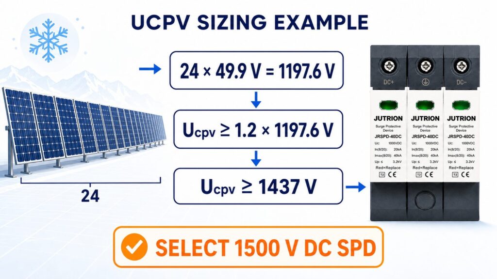
ເອົາສະຕຣິງທີ່ມີ 24 ໂມດູນ, ແຕ່ລະໂມດູນມີແຮງດັນວົງຈອນເປີດ STC 49.5 V.
- Uoc(max) ຂອງແຜງທີ່ STC = 24 × 49.5 V = 1188 V.
- ນຳໃຊ້ສ່ວນເຜືອມາດຕະຖານ: Ucpv ≥ 1.2 × 1188 V = 1426 V.
- ເລືອກລະດັບແຮງດັນຖັດຂຶ້ນໄປຈາກຕົວເລກນັ້ນ: SPD ກະແສຕົງ 1500 V (Ucpv ຖືກຈັດອັນດັບທີ່ 1500 V).
ກວດສອບຄືນຕອນເຊົ້າອາກາດໜາວສຳລັບສະຖານທີ່ທີ່ຮຸນແຮງ. ທີ່ອຸນຫະພູມເຊລຕໍ່າສຸດທີ່ອອກແບບໄວ້ −10 °C, ພົດອຸນຫະພູມແມ່ນການຫຼຸດລົງ 35 ອົງສາ × 0.3 %/°C ≈ +10.5 %, ດັ່ງນັ້ນ Voc ຈຶ່ງເພີ່ມຂຶ້ນເປັນປະມານ 1188 × 1.105 ≈ 1313 V — ຍັງຕໍ່າກວ່າ 1500 V Ucpv ຢ່າງສະບາຍ. ສຳລັບພູມອາກາດທີ່ໜາວຫຼາຍ, ໃຫ້ຄຳນວນ Voc ທີ່ອຸນຫະພູມຕໍ່າສຸດທີ່ທ່ານອອກແບບເອງ ໂດຍໃຊ້ຄ່າສຳປະສິດອຸນຫະພູມຂອງໂມດູນ ແລະ ຢືນຢັນວ່າ Ucpv ຍັງສູງກວ່າຄ່ານັ້ນ; ປັດໄຈ 1.2 ກວມເອົາເງື່ອນໄຂທຳມະດາ, ບໍ່ແມ່ນການຕິດຕັ້ງແບບອາກຕິກ. ຈາກນັ້ນຈຶ່ງເທບໃສ່ລາຍຊື່ລະດັບທີ່ກຳນົດໄວ້:
- ລະບົບສູງເຖິງ ~600 V → ຊັ້ນ Ucpv 600 V (ຫຼືສູງກວ່າ).
- ລະບົບ 1000 V → ຊັ້ນ 1000 V.
- ລະບົບ 1500 V → ຊັ້ນ 1500 V.
ປະເພດ 2 ຫຼື ປະເພດ 1+2? ຈັບຄູ່ SPD ກັບການສຳຜັດຟ້າຜ່າ
ປະເພດແມ່ນການຕັດສິນໃຈດ້ານຄວາມສ່ຽງຟ້າຜ່າ, ບໍ່ແມ່ນຊັ້ນຄຸນນະພາບ. ມັນຕາມມາຈາກຂໍ້ມູນປ້ອນທີ່ສີ່ຂ້າງເທິງ ແລະ ຈາກການອອກແບບປ້ອງກັນຟ້າຜ່າຂອງສະຖານທີ່.
- ປະເພດ 2 ອຸປະກອນຖືກທົດສອບດ້ວຍຮູບຄື້ນ 8/20 µs ແລະ ຖືກຈັດອັນດັບດ້ວຍກະແສດິສຊາຈທີ່ກຳນົດ (In) ແລະ ກະແສດິສຊາຈສູງສຸດ (Imax). ພວກມັນຮັບມືກັບເຊີຈທີ່ເກີດຈາກການເໜັງນຳ ແລະ ທຣານຊຽນຈາກການສະຫຼັບ — ໄພຂົ່ມຂູ່ປະຈຳວັນຢູ່ເທິງຫຼັງຄາອາຄານທີ່ບໍ່ມີລະບົບປ້ອງກັນຟ້າຜ່າພາຍນອກ. ນີ້ກວມເອົາອາເຣຫຼັງຄາທີ່ຢູ່ອາໄສ ແລະ ການຄ້າສ່ວນໃຫຍ່.
- ປະເພດ 1+2 ອຸປະກອນເພີ່ມການຈັດອັນດັບກະແສຟ້າຜ່າບາງສ່ວນ, ກະແສອິມພັລສ໌ Iimp ທີ່ທົດສອບດ້ວຍຮູບຄື້ນ 10/350 µs, ໃນຂະນະທີ່ຍັງໃຫ້ການປ້ອງກັນປະເພດ 2. ລະບຸພວກມັນໃນບ່ອນທີ່ມີລະບົບປ້ອງກັນຟ້າຜ່າ ແລະ ບໍ່ສາມາດຮັກສາໄລຍະຫ່າງແຍກໄດ້, ຢູ່ອາເຣຕິດດິນທີ່ເປີດໂລ່ງ ແລະ ຢູ່ເທິງພູ, ແລະ ໃນເຂດທີ່ມີຄວາມໜາແໜ້ນຂອງຟ້າຜ່າສູງ — ທຸກບ່ອນທີ່ສ່ວນແບ່ງຂອງກະແສຟ້າຜ່າໂດຍກົງສາມາດຖືກນຳເຂົ້າສູ່ດ້ານ DC.
ຄຳຖາມຕັດສິນແມ່ນວ່າກະແສຟ້າຜ່າໂດຍກົງ ຫຼື ບາງສ່ວນສາມາດເຂົ້າເຖິງສາຍໄຟອາເຣໄດ້ຫຼືບໍ່, ເຊິ່ງຖືກປະເມີນຜ່ານການວິເຄາະຄວາມສ່ຽງດ້ານການປ້ອງກັນຟ້າຜ່າຂອງສະຖານທີ່ (ຊຸດ IEC 62305). ຖ້າຄຳຕອບແມ່ນແມ່ນ, ຄວາມສາມາດ Iimp ເພີ່ມເຕີມຂອງອຸປະກອນປະເພດ 1+2 ກຳລັງປ້ອງກັນພະລັງງານທີ່ການທົດສອບປະເພດ 2 ບໍ່ໄດ້ສະແດງເຖິງ. ຖ້າຄຳຕອບແມ່ນບໍ່ຢ່າງຊັດເຈນ, ອຸປະກອນປະເພດ 2 ທີ່ຖືກລະບຸຢ່າງດີແມ່ນທາງເລືອກທີ່ຖືກຕ້ອງ ແລະ ປະຫຍັດກວ່າ, ບໍ່ແມ່ນການປະນີປະນອມ.
ການຈັດອັນດັບດ້ານ DC ທີ່ປ້ອງກັນອິນເວີຣ໌ເຕີຣ໌ໄດ້ແທ້ຈິງ
ເມື່ອແຮງດັນ ແລະ ປະເພດຖືກກຳນົດແລ້ວ, ສາມການຈັດອັນດັບກຳນົດວ່າອິນເວີຣ໌ເຕີຣ໌ທີ່ຢູ່ຫຼັງ SPD ຖືກປ້ອງກັນແທ້ຈິງຫຼືບໍ່:
| ການຈັດອັນດັບ | ສິ່ງທີ່ມັນສະແດງເຖິງ | ກົດການເລືອກ |
|---|---|---|
| ຂຶ້ນ (ລະດັບການປ້ອງກັນແຮງດັນ) | ແຮງດັນຜ່ານທີ່ SPD ອະນຸຍາດໃຫ້ເຂົ້າເຖິງອຸປະກອນໃນລະຫວ່າງເຊີຈ | ຮັກສາ Up ໃຫ້ຕ່ຳກວ່າແຮງດັນທົນທານອິມພັລສ໌ (Uw) ຂອງອິນພຸດ DC ຂອງອິນເວີຣ໌ເຕີຣ໌ຢ່າງໜ້ອຍ ~20 %, ເພື່ອໃຫ້ມີສ່ວນຕ່າງເຫຼືອຫຼັງຈາກການສູນເສຍຄວາມຍາວສາຍ |
| In (ກະແສດິສຊາຈທີ່ກຳນົດ) | ກະແສ 8/20 µs ທີ່ SPD ສາມາດເບນທາງອອກໄດ້ຊ້ຳໆໂດຍບໍ່ເສຍຫາຍ | In ທີ່ສູງກວ່າໃຫ້ພື້ນທີ່ເຜື່ອຫຼາຍກວ່າ ແລະ ອາຍຸການໃຊ້ງານຍາວກວ່າຢູ່ສະຖານທີ່ທີ່ເປີດໂລ່ງ; ຖືວ່າມັນເປັນການຈັດອັນດັບການເຮັດວຽກ, ບໍ່ແມ່ນຄ່າສູງສຸດ |
| Imax (ກະແສດິສຊາຈສູງສຸດ) | ກະແສ 8/20 µs ເຫດການດ່ຽວທີ່ SPD ສາມາດຢູ່ລອດໄດ້ຄັ້ງດຽວ | ເພດານການຢູ່ລອດສຳລັບເຫດການຮຸນແຮງ, ບໍ່ແມ່ນຕົວເລກການເຮັດວຽກ; ລະບຸດ້ວຍສ່ວນຕ່າງທີ່ສູງກວ່າເຊີຈທີ່ຄາດວ່າຈະເກີດ, ບໍ່ແມ່ນເທົ່າກັບມັນ |
Up ແມ່ນການຈັດອັນດັບທີ່ຖືກລະເລີຍເລື້ອຍທີ່ສຸດ ແລະ ຕັດສິນໂດຍກົງທີ່ສຸດວ່າອິນເວີຣ໌ເຕີຣ໌ຈະຢູ່ລອດຫຼືບໍ່. ອຸປະກອນທີ່ມີ Imax ທີ່ໜ້າປະທັບໃຈ ແຕ່ Up ທີ່ໃກ້ກັບແຮງດັນທົນທານຂອງອິນເວີຣ໌ເຕີຣ໌ ຈະປ່ອຍໃຫ້ທຣານຊຽນຜ່ານທີ່ອີເລັກໂທຣນິກບໍ່ສາມາດດູດຊຶມໄດ້. ຕົວຢ່າງເຊັ່ນ ກຸ່ມຜະລິດຕະພັນ DC ພະລັງງານແສງອາທິດ JUTRION ລະບຸ Up ໃນອຸປະກອນ 40 kA (8/20 µs Imax) ຂອງມັນ ເພື່ອໃຫ້ການປະສານງານນີ້ສາມາດຖືກກວດສອບກັບເອກະສານຂໍ້ມູນຂອງອິນເວີຣ໌ເຕີຣ໌ ແທນທີ່ຈະສົມມຸດເອົາ.
ປະສານງານຂັ້ນຕອນຕ່າງໆ, ແລະ ກວດສອບ SPD ໃນຕົວຂອງອິນເວີຣ໌ເຕີຣ໌
ສອງຄຳຖາມທີ່ກ່ຽວຂ້ອງກັບ SPD ຕັດສິນວ່າອຸປະກອນເພີ່ມເຕີມຊ່ວຍໄດ້ ຫຼື ພຽງແຕ່ເສຍເງິນເປົ່າ.
ການປະສານງານດ້ານພະລັງງານລະຫວ່າງຂັ້ນຕອນ. ເມື່ອອຸປະກອນປະເພດ 1+2 ຢູ່ແຖວແຜງ ຫຼື ຕູ້ລວມສາຍ ເຮັດວຽກຮ່ວມກັບອຸປະກອນປະເພດ 2 ຢູ່ອິນເວີຣ໌ເຕີ, ທັງສອງຕ້ອງຖືກປະສານພະລັງງານເພື່ອໃຫ້ອຸປະກອນດ້ານຕົ້ນທາງຮັບແຮງກະທົບພະລັງງານສູງ ແລະ ອຸປະກອນດ້ານປາຍທາງພຽງແຕ່ຕັດສ່ວນທີ່ເຫຼືອ. ການປະສານງານເຮັດໄດ້ໂດຍການຮັກສາສາຍ DC ໃຫ້ຍາວພຽງພໍລະຫວ່າງຂັ້ນຕອນ — ປະມານ 10 ແມັດໃຫ້ການແຍກແບບ inductive ພຽງພໍ — ຫຼື, ບ່ອນທີ່ໄລຍະຫ່າງນັ້ນບໍ່ມີ, ໂດຍໃຊ້ຕົວເໜັ່ງນຳແຍກ ຫຼື ຊຸດທີ່ຖືກຢັ້ງຢືນການປະສານງານໂດຍຜູ້ຜະລິດ. ການປະສົມອຸປະກອນຂອງສອງຜູ້ຜະລິດໂດຍບໍ່ມີການແຍກທີ່ກຳນົດໄວ້ອາດເຮັດໃຫ້ SPD ດ້ານປາຍທາງຮັບແຮງເກີນ; ໃຫ້ປະຕິບັດຕາມຂໍ້ມູນການປະສານງານຂອງຜູ້ຜະລິດ ແທນທີ່ຈະສົມມຸດວ່າອຸປະກອນສອງອັນໃດກໍຕາມຈະເຮັດວຽກຮ່ວມກັນໄດ້.
ອິນເວີຣ໌ເຕີອາດມີ SPD DC ຢູ່ແລ້ວ. ອິນເວີຣ໌ເຕີສະຕຣິງທັນສະໄໝຫຼາຍລຸ້ນມາພ້ອມກັບ SPD DC ປະເພດ 2 ໃນຕົວ ຫຼື ຊ່ອງສຽບສຳລັບໂມດູນແບບຖອດໄດ້. ກວດສອບສິ່ງນີ້ກ່ອນກຳນົດອຸປະກອນພາຍນອກທີ່ຂາເຂົ້າ DC ຂອງອິນເວີຣ໌ເຕີ: ຖ້າອິນເວີຣ໌ເຕີປ້ອງກັນຂົ້ວຂອງມັນເອງແລ້ວ, ຄວາມພະຍາຍາມພາຍນອກຄວນຢູ່ທີ່ປາຍແຖວແຜງ ຫຼື ຕູ້ລວມສາຍ, ບ່ອນທີ່ສາຍ DC ຍາວກັບບ້ານບໍ່ໄດ້ຮັບການປ້ອງກັນ. ການກຳນົດ SPD ອັນທີສອງຫ່າງຈາກອັນທີ່ມີໃນຕົວ 200 ມມ ບໍ່ໄດ້ປ້ອງກັນຫຍັງໃໝ່ ແລະ ເພີ່ມຈຸດທີ່ອາດເສຍຫາຍ.
ກະແສຟອລຕ໌, ແບັກອັບ, ແລະ ຕົວຕັດວົງຈອນຄວາມຮ້ອນ: ສາຍໂສ້ຄວາມປອດໄພທີ່ຄູ່ແຂ່ງຂ້າມໄປ
ນີ້ແມ່ນຈຸດທີ່ການເລືອກລະດັບສະເປັກແຕກຕ່າງຈາກການເລືອກຈາກແຄັດຕາລັອກ, ແລະ ເປັນຈຸດທີ່ບົດຄວາມ SPD ໂຊລາເຊລສ່ວນໃຫຍ່ມິດງຽບ. ສາມຂໍ້ກຳນົດທີ່ເຊື່ອມໂຍງກັນຮັກສາບໍ່ໃຫ້ SPD ທີ່ກຳລັງເສຍຫາຍກາຍເປັນຟອລຕ໌ DC.
ຄວາມທົນທານຕໍ່ກະແສລັດວົງຈອນ (Iscpv / SCCR)
SPD ຕ້ອງທົນຕໍ່ກະແສລັດວົງຈອນທີ່ຄາດການໄດ້ຂອງແຜງຢູ່ຕຳແໜ່ງທີ່ຕິດຕັ້ງ. ປຽບທຽບຄ່າກະແສທົນຕໍ່ລັດວົງຈອນທີ່ກຳນົດໄວ້ຂອງອຸປະກອນ, Iscpv, ກັບກະແສລັດວົງຈອນສູງສຸດຂອງແຜງ — ປະມານ 1.25 × ຄ່າ STC Isc ຂອງໂມດູນສຳລັບຈຳນວນສາຍຂະໜານທີ່ກ່ຽວຂ້ອງ, ຕົວຄູນ 1.25 ກວມເອົາການເພີ່ມຂຶ້ນຈາກຄວາມເຂັ້ມແສງ ແລະ ອຸນຫະພູມ ຕາມແນວທາງການອອກແບບແຜງ PV (IEC 62548). ສຳລັບກ່ອງລວມສາຍທີ່ຮວບຮວມສາຍຂະໜານສີ່ສາຍຂອງໂມດູນທີ່ມີຄ່າກະແສລັດວົງຈອນ STC 13.5 A, ນັ້ນແມ່ນ 1.25 × 13.5 A × 4 ≈ 68 A; SPD ຢູ່ຕຳແໜ່ງນັ້ນຕ້ອງມີຄ່າ Iscpv ເທົ່າກັບ ຫຼື ສູງກວ່າປະມານ 68 A. ຄ່າ Iscpv ຂອງ SPD ຕ້ອງເທົ່າກັບ ຫຼື ຫຼາຍກວ່າຕົວເລກນັ້ນໃນທຸກຕຳແໜ່ງທີ່ຕິດຕັ້ງ.
ຕົວຕັດວົງຈອນຄວາມຮ້ອນແບບປະສົມປະສານ
ເນື່ອງຈາກອາກໄຟຟ້າ DC ບໍ່ມີຈຸດທີ່ກະແສເປັນສູນຕາມທຳມະຊາດ, IEC 61643-31 ຈຶ່ງຮຽກຮ້ອງໃຫ້ SPD ຕັດຕົວເອງອອກເມື່ອເກີດຄວາມລົ້ມເຫຼວ. ໃນພາກປະຕິບັດ ນີ້ແມ່ນ ຕົວຕັດວົງຈອນຄວາມຮ້ອນ ທີ່ຕິດຢູ່ກັບວາຣິສເຕີ ເຊິ່ງເປີດທາງປ້ອງກັນອອກ ເມື່ອອົງປະກອບຮ້ອນເກີນໄປໃນຕອນສິ້ນອາຍຸການໃຊ້ງານ. ມັນເປັນອົງປະກອບຄວາມປອດໄພທີ່ບັງຄັບຂອງ SPD DC ຂອງແຜງ PV, ບໍ່ແມ່ນຄຸນສົມບັດພິເສດ — ອຸປະກອນທີ່ບໍ່ມີມັນ ບໍ່ຄວນມີບ່ອນຢູ່ໃນຝັ່ງ DC.
ເມື່ອຕ້ອງການອຸປະກອນສຳຮອງພາຍນອກ
ຟິວສຳຮອງພາຍນອກ ຫຼື ຕົວຕັດວົງຈອນທີ່ກຳນົດສຳລັບ DC ແມ່ນຈຳເປັນພຽງແຕ່ເມື່ອກະແສລັດວົງຈອນທີ່ຄາດການໄດ້ຂອງແຜງ ເກີນ ຄ່າ Iscpv ຂອງ SPD. SPD DC ຂອງແຜງ PV ຫຼາຍຊະນິດຖືກກຳນົດໃຫ້ທົນຕໍ່ກະແສລັດວົງຈອນເຕັມຂອງສາຍແຜງ ແລະ ບໍ່ຈຳເປັນຕ້ອງມີສຳຮອງພາຍນອກເລີຍ; ການເພີ່ມຟິວທີ່ບໍ່ຈຳເປັນພຽງແຕ່ເພີ່ມຈຸດລົ້ມເຫຼວ ແລະ ຄວາມຍາວສາຍໄຟທີ່ເພີ່ມຂຶ້ນ. ອ່ານເອກະສານຂໍ້ມູນຂອງ SPD: ມັນລະບຸກະແສລັດວົງຈອນສູງສຸດຂອງແຜງທີ່ອຸປະກອນທົນໄດ້ໂດຍບໍ່ມີການຊ່ວຍເຫຼືອ ແລະ, ບ່ອນທີ່ຈຳເປັນຕ້ອງມີສຳຮອງ, ຄ່າກຳນົດທີ່ແນະນຳ. ໃນໂຮງງານຂະໜາດໃຫຍ່, ຍັງຄວນລະບຸອຸປະກອນທີ່ມີ ໜ້າສຳພັດສັນຍານລາຍງານທາງໄກ ດັ່ງນັ້ນ ຜູ້ປະຕິບັດງານຈຶ່ງເຫັນ SPD ທີ່ໝົດອາຍຸການໃຊ້ງານຢູ່ໃນລະບົບຕິດຕາມ ແທນທີ່ຈະເປີດຕູ້ເພື່ອເບິ່ງທຸງສະຖານະດ້ວຍຕາເປົ່າ.
ການກຳນົດຄ່າການເດີນສາຍ: ແບບ 2 ຂົ້ວມາດຕະຖານ ທຽບກັບ ແບບ Y ສຳລັບແຜງທີ່ຕໍ່ລົງດິນ ແລະ ແບບລອຍ
PV DC SPDs ມີຫຼາຍກວ່າໜຶ່ງໂຄງສ້າງພາຍໃນ, ແລະ ການເລືອກແມ່ນຂຶ້ນກັບການຈັດວາງສາຍດິນຂອງແຜງ. ສອງແບບທີ່ທ່ານຈະພົບແມ່ນ:
- ມາດຕະຖານ 2 ຂົ້ວ: a varistor from the positive pole to earth and another from the negative pole to earth. Simple and appropriate for functionally earthed systems where that arrangement suits the array.
- Y-configuration (also called 3+0 or total protection): the positive and negative poles each connect through a varistor to a common node, and that node connects to earth through a gas discharge tube (spark gap). Because the spark gap blocks continuous DC to earth, a single failed varistor cannot create a permanent pole-to-earth fault, and the arrangement suits both floating (unearthed) and functionally earthed arrays. It is the configuration most PV DC SPDs use for exactly this reason.
Match the configuration to the array’s earthing arrangement and confirm it against the SPD datasheet; a device chosen only on voltage and current but wired in the wrong topology can leave a mode of protection ineffective or introduce leakage.
Earthing, bonding, and conductor sizing
An SPD is only as good as the earth path it discharges into. The surge current the device diverts has to reach the mass of earth through a low-impedance route, and if that route is long, thin, or loosely terminated, the let-through voltage rises no matter how good the device’s Up is.
- Conductor cross-section. Size the SPD’s connecting and earthing conductors for the surge, not just the working current. Common installation practice (IEC 60364-5-53) is at least 6 mm² copper for a Type 2 device and at least 16 mm² copper for a Type 1 or Type 1+2 device that carries partial lightning current. Confirm the figure against local wiring rules and the SPD instructions.
- Equipotential bonding. Bond the SPD’s earth terminal to the array frame earthing and the main earthing system so that, during a surge, the whole installation rises and falls together and no dangerous potential difference appears across the inverter. On systems with a lightning protection system, this bonding is part of the LPS earthing design, not a separate afterthought.
- Terminations. Keep terminations tight and corrosion-protected in an outdoor combiner box; a high-resistance joint in the earth path quietly defeats the device.
Earthing is the part of the specification a datasheet cannot fix for you. Two identical SPDs, one with a short 16 mm² bonded earth and one with a long undersized tail, protect the inverter very differently.
Where to install, and the two rules that set let-through voltage
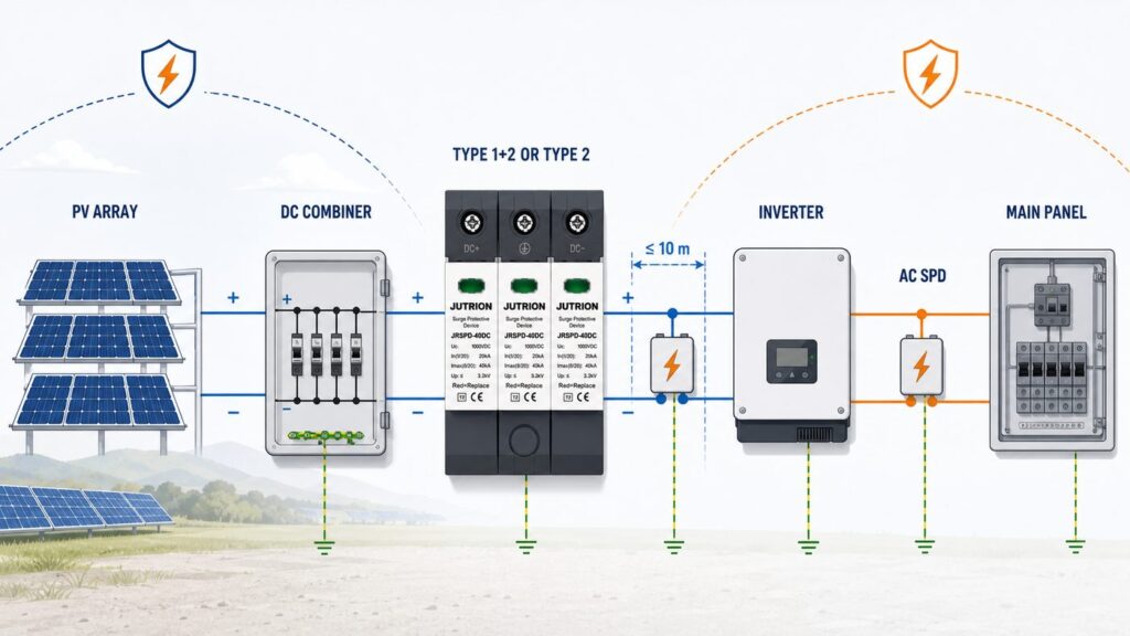
An SPD only protects what sits close to it, so location is part of the specification, not an afterthought.
- At the inverter DC input — unless the inverter already contains a coordinated DC SPD. This is the equipment you are protecting.
- At the array or combiner box — when the DC cable run between array and inverter exceeds roughly 10 metres. Beyond that distance a surge induced on the long DC cable can build enough voltage that one SPD at the far end no longer protects both ends, so protect at both.
- At the combiner and recombiner boxes — on multi-string and large ground-mount systems, one SPD per string group plus the DC disconnect, following the array’s protection zones.
Two installation rules then decide how much voltage actually reaches the equipment:
- The 0.5 m rule. Keep the total connecting-lead length — the loop through the live poles and the earth conductor — to about 0.5 m. Every extra length of lead adds inductive voltage (V = L × di/dt) on top of the device’s Up during a fast surge, so neat cabling routed the long way round the enclosure quietly raises the let-through voltage. Take the shortest path to the busbar and the earth bar.
- Connect earth first. Establish the protective-earth path before the live conductors so the discharge path exists from the moment the SPD is live.
Read the datasheet: a PV DC SPD parameter decoder
A specification is only safe once you can read the datasheet without guessing. These are the lines that matter on a PV DC SPD, and what each one is telling you.
| Datasheet line | What it means | What to check |
|---|---|---|
| Ucpv (Uc DC) | Maximum continuous DC operating voltage | ≥ 1.2 × array maximum Voc, per mode of protection |
| Type / Class | Type 2 (Class II) or Type 1+2 (Class I+II) | Matches the lightning-exposure decision |
| Iimp (10/350 µs) | Partial-lightning impulse current, Type 1 test | Present and adequate only where Type 1+2 is required |
| In (8/20 µs) | Nominal discharge current, repeated duty | Sized to site exposure; the working rating |
| Imax (8/20 µs) | Maximum single discharge current | Comfortable margin above expected surge |
| ຂຶ້ນ | Voltage protection level (let-through) | ≥ 20 % below the inverter DC withstand voltage |
| Iscpv / SCCR | Short-circuit withstand at the terminals | ≥ array maximum short-circuit current at that point |
| Response time (tA) | How fast the element clamps | Nanosecond-order for MOV-based devices |
| Thermal disconnector / indicator | Internal fail-safe and status window | Present; green/red or flag indication; pluggable module preferred |
| Remote signaling contact | Volt-free contact for monitoring | Specify on large or unattended plants |
| Operating temperature / IP | Environmental range and ingress rating | Suits the combiner-box climate and enclosure |
| Poles / mounting / terminals | 2-pole or Y, 35 mm DIN rail, conductor capacity | Matches earthing arrangement and cable size |
If any of these lines is missing from a datasheet — particularly Ucpv, Iscpv, or the thermal disconnector — treat the omission as a reason to ask, not an assumption to make. A device that will not state its short-circuit withstand or its DC voltage rating is not documented for the DC side.
Don’t forget the AC side: protecting the whole PV system
A PV surge-protection specification that stops at the DC side is only half a specification. The same lightning or switching event that threatens the array reaches the inverter’s AC output and the point of connection to the building or grid, and that side needs its own SPD to IEC 61643-11 — an AC device, sized to the AC system voltage (for example Uc around 275 V line-to-earth on a 230/400 V system), not a DC device.
Coordinate the two sides: a Type 2 AC SPD at the inverter output and main AC board for a building with no external LPS, or a Type 1+2 AC SPD at the origin where an LPS is present, mirroring the logic used on the DC side. JUTRION’s AC range — the JUSPD-40AC (Type 2) and JUSPD-12.5AC (Type 1+2) — covers this side to the same standards, so a single supplier can provide a coordinated DC-and-AC set rather than two unmatched halves.
Monitoring, maintenance, and replacement
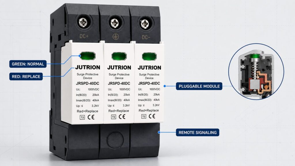
An SPD is a wear part. Every surge it diverts consumes a little of the varistor’s life, and the device is designed to reach end of life and disconnect rather than fail catastrophically. Specifying for that lifecycle is part of selection, not a separate maintenance topic.
- Pluggable modules. Prefer a device with a pluggable protection module and a base that stays wired in. Replacement then takes seconds and does not disturb the DC terminations or the earth path — important on a live PV system that cannot simply be switched off in daylight.
- Status indication. A mechanical flag or a green-to-red window shows at a glance whether the module still protects. On a large or roof-mounted array where no one inspects the combiner box weekly, add the remote signaling contact and wire it back to the monitoring system so an end-of-life module raises an alarm.
- Inspection and replacement. Check the indicators at each scheduled maintenance visit and after any known severe lightning event in the area. When the window shows red or the module has disconnected, replace the module — it no longer protects, even though the array keeps generating. Isolate safely and follow the manufacturer’s live-working guidance before removing a module on an energised DC system.
Designing the array’s protection so a failed module can be seen and swapped quickly is what keeps the protection real years after commissioning, rather than a green light everyone assumes is still green.
Worked example: a 100 kW commercial rooftop
The method comes together on a single realistic project. This case is illustrative, not a specific JUTRION installation, but the arithmetic is the arithmetic you would actually do.
The system. A 100 kWp flat commercial roof, 1500 V string inverters, no external lightning protection system on the building, moderate lightning-flash density. Modules: 550 W, Voc(STC) 49.9 V, Isc(STC) 13.85 A, temperature coefficient of Voc about −0.28 %/°C. Strings of 24 modules, four strings per combiner box, combiner boxes about 15 m of cable from the inverters.
- Voltage. String Voc(STC) = 24 × 49.9 = 1197.6 V. Ucpv ≥ 1.2 × 1197.6 = 1437 V → a 1500 V-class device. Cold check at a design minimum of −5 °C: +8.4 % on Voc ≈ 1298 V, still under 1500 V. The string length is safe for a 1500 V system; a 26-module string would have pushed Ucpv to ~1560 V and out of the 1500 V class.
- Type. No external LPS and a building roof → ປະເພດ 2 is correct at both the combiner and the inverter side. A Type 1+2 would be specified only if an LPS were added or the site were highly exposed.
- Short-circuit withstand. Per combiner, four parallel strings: Iscpv ≥ 1.25 × 13.85 × 4 ≈ 69 A. Choose a device whose Iscpv clears 69 A; most will, so no external backup fuse is needed — confirm on the datasheet.
- Locations and coordination. The 15 m run exceeds 10 m, so protect both the combiner boxes and the inverter DC input; the 15 m of cable also provides the decoupling that keeps the two stages energy-coordinated. First, though, check whether the inverters already contain an integrated DC SPD — if they do, keep the combiner-box devices and skip the redundant inverter-input ones.
- Up and earthing. Confirm each device’s Up sits at least 20 % below the inverter’s DC withstand voltage, and earth each SPD with at least 6 mm² copper bonded to the array frame and main earth.
- AC side. Add a Type 2 AC SPD at the inverter AC output / main LV board, Uc about 275 V, to IEC 61643-11.
Result: Type 2, 1500 V-class DC SPDs with Iscpv ≥ ~70 A at each combiner box and (if the inverter has no integrated device) at each inverter DC input, remote signaling on the combiner units for roof-level monitoring, plus a Type 2 AC SPD at the AC board. That is a coordinated, documented specification — not a box picked on discharge current alone.
Selection matrix: from PV system to a specified DC SPD
The matrix below turns the four inputs into a first-pass specification. Read across from the system and its exposure to the type, voltage class, discharge rating, and where the device belongs. Confirm the exact figures against the array calculation and the SPD datasheet before ordering.
| PV system and exposure | SPD type | Ucpv class | ຄ່າພິກັດການປົດປ່ອຍ | Location |
|---|---|---|---|---|
| Residential rooftop, no external LPS | ປະເພດ 2 | Match system (600 / 1000 V) | In sized to exposure; Imax with margin | Inverter DC input; add array end if run > ~10 m |
| Commercial rooftop, no external LPS | ປະເພດ 2 | 1000 / 1500 V | Higher In for repeated duty | Inverter DC input and combiner box |
| Commercial rooftop with LPS present | ປະເພດ 1+2 | 1000 / 1500 V | Iimp (10/350 µs) plus In/Imax | Inverter DC input and combiner box |
| Exposed ground-mount / hilltop / high flash density | ປະເພດ 1+2 | 1500 V | Iimp rated for partial lightning current | Combiner and recombiner boxes; inverter DC input |
| Utility-scale free-field array | ປະເພດ 1+2 | 1500 V | High Iimp and In; remote signaling | Every combiner/recombiner and inverter station, per protection zones |
Notice what the matrix does not include: a battery or energy-storage DC bus. IEC 61643-31 and IEC 61643-32 cover the PV generator and inverter DC side up to 1500 V DC; they explicitly do not cover PV systems with energy storage. A battery DC bus needs its surge protection assessed under its own requirements, so do not assume a PV-string SPD is a drop-in for the storage side — specify that separately.
The mistakes that undersize or void a PV DC SPD
Most failed or ineffective PV surge protection traces back to a short list of avoidable errors. Each one has a direct consequence.
- Using an AC SPD on the DC side. No DC-capable disconnector, wrong voltage basis — a fire risk, not a protection device.
- Sizing Ucpv to the nominal voltage. Ignoring the cold-morning Voc rise overstresses the device and trips its thermal disconnector early. Always size to 1.2 × the maximum Voc.
- Over-long or oversized strings. A string whose Voc pushes Ucpv past the 1500 V class leaves no compliant SPD; fix it at design time by shortening the string.
- Ignoring Iscpv. An SPD with a short-circuit withstand below the array’s fault current can fail violently instead of disconnecting cleanly.
- Leads too long. Exceeding the 0.5 m connecting-lead target adds inductive voltage and defeats a low Up.
- Doubling up on an integrated SPD. Fitting an external device beside the inverter’s own coordinated SPD protects nothing new and adds a failure point — put the effort at the unprotected array end.
- Uncoordinated stages. Two SPDs with no decoupling distance or defined inductor can leave the downstream device overstressed. Keep ~10 m between stages or follow the maker’s coordination data.
- No monitoring on unattended arrays. A red window on a rooftop combiner box no one opens means months of unprotected operation; specify the remote contact.
Turn the selection into an RFQ line
A selection is only useful once it becomes something a supplier can quote against without a second round of questions. The reader job at the end of this process is a single, unambiguous specification line. Capture these fields and an enquiry can be answered in one reply:
- Application and standard: PV DC side, to IEC 61643-31; state Type 2 or Type 1+2.
- System voltage class and Ucpv: the 600 / 1000 / 1500 V class and the minimum Ucpv from the 1.2 × Voc calculation.
- Array maximum Voc: the figure Ucpv was sized against, so the supplier can verify the margin.
- Discharge rating: required In and Imax (8/20 µs), and Iimp (10/350 µs) for a Type 1+2 device.
- Voltage protection level: the maximum acceptable Up, derived from the inverter’s DC withstand voltage.
- Short-circuit withstand: the minimum Iscpv from the array short-circuit calculation, and whether an external backup device is expected.
- Configuration and poles: standard 2-pole or Y-configuration, matched to the earthing arrangement.
- Installation point and monitoring: inverter input, combiner, or recombiner; DIN-rail format; and whether a remote signaling contact is required.
That line removes the guesswork on both sides and is the difference between a quote and a conversation.
Recommended DC SPD by project type
Bringing the method back to real decisions, here is how the specification typically lands for four common projects, mapped to the two JUTRION solar DC series — JRSPD-40DC-II (Type 2) and JRSPD-40DC-I+II (Type 1+2), both to IEC 61643-31, up to DC 1500 V, 40 kA Imax.
- Residential rooftop string inverter (no LPS): a Type 2 device (JRSPD-40DC-II class) at the inverter DC input, Ucpv matched to the string’s cold-morning Voc, sized for occasional induced surges. Add a second at the array end only if the DC run is long.
- Commercial rooftop (no LPS): Type 2 at both the combiner box and the inverter DC input, a higher nominal discharge current for repeated duty, and Up checked against the inverter’s DC withstand.
- Exposed ground-mount or utility array: Type 1+2 (JRSPD-40DC-I+II class) with a real Iimp rating at combiner and recombiner boxes, 1500 V class, and a remote signaling contact for plant monitoring — this is where the partial-lightning-current capability earns its cost.
- Array with a lightning protection system: Type 1+2 wherever separation distance to down-conductors cannot be maintained, coordinated with the LPS design rather than chosen in isolation.
Specify the four inputs first, size Ucpv to 1.2 × the real maximum Voc, choose the type from lightning exposure, then confirm Up, short-circuit withstand, the thermal disconnector, configuration, and earthing against the datasheet. If you want those figures checked against a specific array before you order, the JUTRION AC & DC surge protective device range lists the DC series with the ratings this guide asks for, and the engineering team can confirm the match for your string voltage and site exposure.
References
- IEC 61643-31:2018 — Low-voltage surge protective devices, Part 31: Requirements and test methods for SPDs for photovoltaic installations.
- IEC 61643-32:2017 — Low-voltage surge protective devices, Part 32: SPDs connected to the DC side of photovoltaic installations, selection and application principles.
- IEC 62305 series — Protection against lightning (risk assessment and lightning protection system coordination).
- IEC 62548 — Photovoltaic (PV) arrays: design requirements (basis for array maximum short-circuit current).
- IEC 60364-5-53 — Low-voltage electrical installations: selection and erection of electrical equipment, isolation, switching and control (SPD connection and conductor sizing).
