

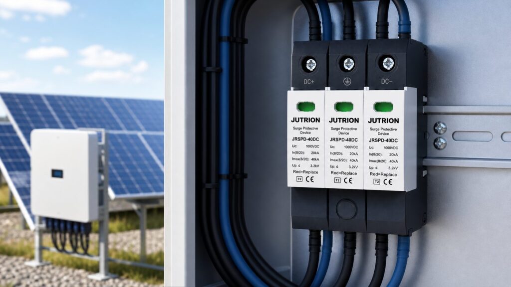
即答:太陽光アレイ用DC SPDの仕様決定方法
DC SPDは4つの入力で選定する:アレイの最大開放電圧、最大短絡電流、雷保護システムの有無、接地方式。最大連続使用電圧は Ucpv ≥ 1.2 × アレイの最大Voc (IEC 61643-32)に合わせて選び、 タイプ2 通常の屋根設置では タイプ 1+2 雷暴露またはLPSがある場合は を選び、機器がDC定格で熱遮断器を内蔵していることを確認する。電圧クラスをシステムに合わせる:600 V、1000 V、または1500 V。.
DCサージ保護デバイスは、ACのものでは決して起こらない故障の仕方をする。寒く晴れた朝、太陽光ストリングは年間で最も高い電圧にあり、太陽が地平線を越えた瞬間からアレイは通電し、内部アークを消弧するための交流のゼロクロスがない。公称システム電圧に対して選ばれたSPD——「1000 Vシステムだから1000 Vのデバイスで十分」——は、恒久的に過ストレス状態に置かれ、漏れ電流が生じ、定格寿命の数か月前に熱遮断器が作動する可能性がある。アレイを保護する数値は公称電圧ではなく、アレイの実際の最大開放電圧に余裕を加えたものであり、仕様の他のすべてはその数値を正しく把握することから導かれる。.
このガイドでは、パネルビルダーやEPC仕様担当者が実際に行う方法でDC側の選定を進める:アレイ入力を確定し、電圧を設定し、タイプを選び、保護定格を設定し、故障電流、熱遮断器、構成、接地、データシート、AC側、ライフサイクルについて確認する。IEC 61643-31(PV DC SPDの製品規格)およびIEC 61643-32(選定と適用)の枠組みに従う。タイプ1、2、3のデバイスとAC/DC両側の広い視点については、 サージ保護デバイス完全ガイド; を参照。本記事は、太陽光アレイが選定を異なるものにする点を深く掘り下げるDC側の補完記事である。.
DC SPDがAC SPDを横に倒したものではない理由
予備のACサージアレスタをPV側に流用したいという誘惑は、太陽光サージ保護において最も危険な近道である。交流は1秒間に100回ゼロを通過する。寿命末期のバリスタが導通し始めると、その自然な電流ゼロが内部遮断器による続流の遮断を助ける。太陽光アレイはゼロクロスのない連続的な直流を供給する。劣化した金属酸化物バリスタはDCアークを持続させ、発熱し、フェイルセーフではなく火災源となる可能性がある。.
保護素子自体は両方の世界で同じように機能する:金属酸化物バリスタ(MOV)は通常電圧では実質的に開回路であり、電圧がしきい値を超えるとナノ秒以内に低インピーダンスに崩壊し、サージを大地へ迂回させて通過電圧をクランプする。一部のデバイスはMOVとガス放電管(GDT)を直列に組み合わせて漏れ電流を排除し、故障モードを改善する。DC側で変わるのはクランプの物理ではなく、素子が経年劣化した後の故障挙動であり、そのためデバイス全体——電圧定格、遮断器、内部トポロジー——がDC用に作られている。.
そのため、準拠したPV DC SPDは異なる構造になっている。連続DC動作の定格を持ち、保護モードは中性点基準のAC電源ではなく、浮遊または機能的に接地されたDCアレイ用に配置され、 熱遮断器を内蔵 保護素子自体は、交流でも直流でも同じように動作します。金属酸化物バリスタ(MOV)は通常電圧では実質的に開回路であり、電圧がしきい値を超えるとナノ秒以内に低インピーダンスへと崩壊し、サージを大地へ迂回させ、通過電圧をクランプします。一部のデバイスは、漏れ電流を排除し故障モードを改善するために、MOVとガス放電管(GDT)を直列に組み合わせています。直流側で変わるのはクランプの物理ではなく、素子が劣化した後の故障挙動であり、そのためデバイス全体——電圧定格、断路器、内部トポロジー——が直流用に作られているのです。 そのため、準拠したPV直流SPDは異なる構造で作られています。連続直流動作の定格を持ち、保護モードは中性点基準の交流電源ではなく、浮遊または機能的接地された直流アレイ向けに配置され、, 内蔵熱断路器.
を備えており、電流ゼロ点に依存せずに故障時にバリスタを切り離します。IEC 61643-31は、これらのデバイスがPV発電機およびインバータの直流側専用であることを明確に規定しています——交流SPDはこれらの要件を満たさず、代用してはなりません。これは、持続的な電源過電圧・不足電圧から守るデバイスとは異なる役割です。マイクロ秒の過渡現象ではなく、供給電圧の緩やかな上昇や低下が懸念される場合は、それは
過電圧・不足電圧保護装置
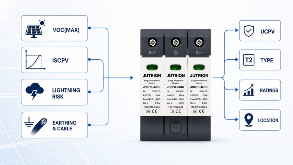
- の領域であり、SPDではありません。. まずアレイから始める:SPDを決める4つの入力.
- SPDデータシート上のすべての定格は、アレイに関する問いに答えるものです。製品を見る前に、以下の4つの入力を確定させてください:. 最大開放電圧、Uoc(max)。.
- 公称システム電圧ではなく——ストリングが到達し得る最高電圧であり、最も寒いと予想される朝の開放時に発生します。これがUcpvを決定します。. 最大短絡電流、Iscpv。.
- SPD設置位置におけるアレイの予想短絡電流で、日射量と温度を考慮して増強されます。これが短絡耐量要件を決定し、外部バックアップデバイスが必要かどうかを決めます。. 雷曝露とLPSの有無。.
サイトに雷保護システムがあるか、露出したまたは雷密度の高い場所にあるか、あるいは引き下げ導体との離隔距離を維持できないか。これがタイプ2かタイプ1+2かを決定します。.
接地方式と直流ケーブル長。
機能的接地または浮遊アレイ、およびアレイとインバータ間のケーブル距離。これがSPDの内部構成と、システムに必要なSPD設置箇所数を決定します。 この4つを正しく把握すれば、仕様の残りは機械的な作業です。これらを推測で済ませると、どれほど大きな公称放電電流定格でも設置を救うことはできません。
Ucpvの選定:1.2 × Vocルールと寒い朝の確認, Ucpv.
は、SPDが劣化することなく無期限に耐えられる最大連続動作電圧です。デバイス内部のすべての保護モード——正極-接地間、負極-接地間、極間——は、すべての使用条件下でアレイの最高電圧を上回っていなければなりません。IEC 61643-32はこのルールを直接的に規定しています:.
Ucpv ≥ 1.2 × Uoc(max)
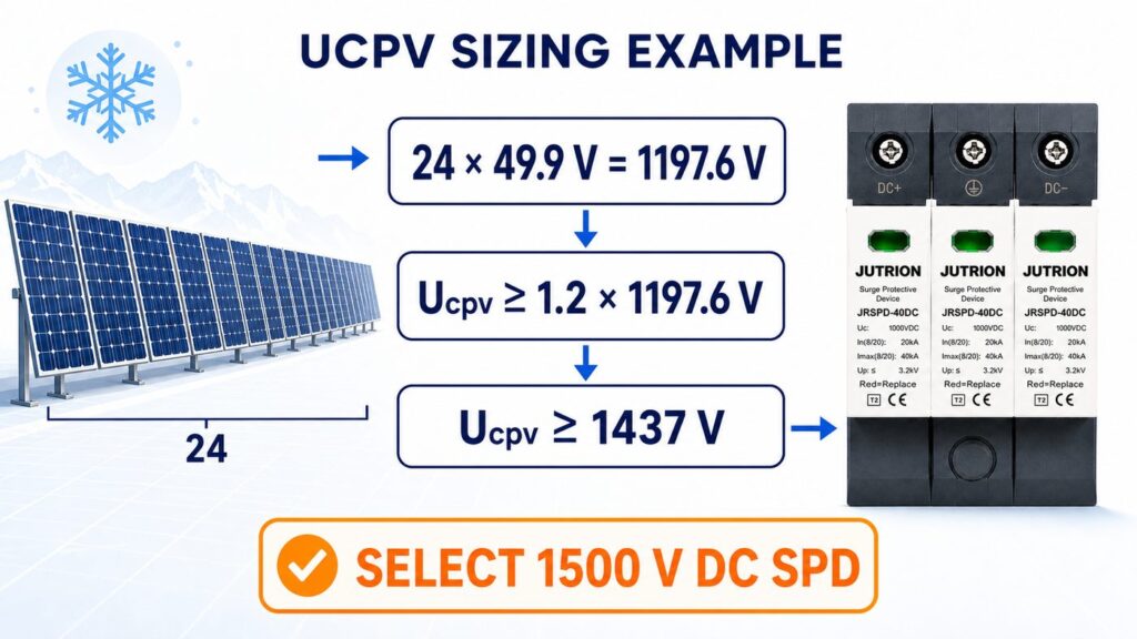
ここで、Uoc(max)は標準試験条件におけるアレイの最大開放電圧です。.
- 2の係数は恣意的な余裕ではありません。開放電圧は、セル温度が標準試験条件の25 °Cを下回ると上昇し、結晶シリコンでは1度あたり約0.3 %です。20 %の余裕は、ほとんどの気候における寒候期の上昇を吸収し、夜明けにアレイがピークに達したときにSPDがUcpv以上で動作することがないようにします。 計算例:1500 Vクラスのストリング.
- 各モジュールのSTC開放電圧が49.5 Vの24枚のモジュールからなるストリングを考えます。 STCでのアレイUoc(max) = 24 × 49.5 V =.
- 1188 V 標準余裕を適用:Ucpv ≥ 1.2 × 1188 V = 1426 V.
その数値を上回る次の電圧クラスを選択: 1500 V DC SPD (Ucpv定格1500 V)。
- 極端なサイトでは寒い朝をクロスチェックします。設計最低セル温度−10 °Cでは、温度項は35度の低下 × 0.3 %/°C ≈ +10.5 %となり、Vocは約1188 × 1.105 ≈.
- 1313 V.
- 1500 V systems → 1500 V class.
Type 2 or Type 1+2? Match the SPD to lightning exposure
The type is a lightning-risk decision, not a quality tier. It follows from the fourth input above and from the site’s lightning protection design.
- タイプ2 devices are tested with the 8/20 µs waveform and rated by nominal discharge current (In) and maximum discharge current (Imax). They handle induced surges and switching transients — the everyday threat on a building rooftop with no external lightning protection system. This covers the majority of residential and commercial rooftop arrays.
- タイプ 1+2 devices add a partial-lightning-current rating, the impulse current Iimp tested with the 10/350 µs waveform, while still providing Type 2 protection. Specify them where a lightning protection system is present and separation distance cannot be maintained, on exposed ground-mount and hilltop arrays, and in high lightning-flash-density regions — anywhere a share of direct lightning current can be conducted into the DC side.
The deciding question is whether direct or partial lightning current can reach the array wiring, which is assessed through the site’s lightning protection risk analysis (the IEC 62305 series). If the answer is yes, the extra Iimp capability of a Type 1+2 device is protecting against an energy the Type 2 test does not represent. If the answer is clearly no, a well-specified Type 2 device is the correct and more economical choice, not a compromise.
The DC-side ratings that actually protect the inverter
Once voltage and type are fixed, three ratings determine whether the inverter behind the SPD is genuinely protected:
| Rating | What it represents | Selection rule |
|---|---|---|
| Up (voltage protection level) | The let-through voltage the SPD allows to reach the equipment during a surge | Keep Up at least ~20 % below the impulse withstand voltage (Uw) of the inverter’s DC input, so a margin remains after lead-length losses |
| In (nominal discharge current) | The 8/20 µs current the SPD can divert repeatedly without damage | Higher In gives more headroom and longer service life at exposed sites; treat it as the working rating, not the maximum |
| Imax (maximum discharge current) | The single-event 8/20 µs current the SPD can survive once | A survival ceiling for a severe event, not a duty figure; specify with margin above the expected surge, not equal to it |
Up is the rating that most often gets ignored and most directly decides whether the inverter survives. A device with an impressive Imax but a Up that sits close to the inverter’s withstand voltage lets through a transient the electronics cannot absorb. The JUTRION solar DC range, for example, specifies Up on its 40 kA (8/20 µs Imax) devices so this coordination can be checked against the inverter datasheet rather than assumed.
Coordinate the stages, and check the inverter’s built-in SPD
Two SPD-related questions decide whether extra devices help or simply waste money.
Energy coordination between stages. When a Type 1+2 device at the array or combiner box works together with a Type 2 device at the inverter, the two must be energy-coordinated so the upstream device takes the high-energy hit and the downstream device only trims the residual. Coordination is achieved by keeping enough DC cable between the stages — roughly 10 metres provides sufficient inductive decoupling — or, where that distance is not available, by a decoupling inductor or a manufacturer-verified coordinated set. Mixing two makers’ devices with no defined decoupling can leave the downstream SPD overstressed; follow the manufacturer’s coordination data rather than assuming any two devices cooperate.
The inverter may already contain a DC SPD. Many modern string inverters ship with an integrated Type 2 DC SPD or a slot for a pluggable module. Confirm this before specifying an external device at the inverter DC input: if the inverter already protects its own terminals, the external effort belongs at the array or combiner end, where a long DC home-run is otherwise unprotected. Specifying a second SPD 200 mm from an existing integrated one protects nothing new and adds a failure point.
Fault current, backup, and the thermal disconnector: the safety chain competitors skip
This is where a spec-grade selection separates from a catalogue pick, and where most solar SPD articles go quiet. Three linked requirements keep a failing SPD from becoming a DC fault.
Short-circuit withstand (Iscpv / SCCR)
The SPD must survive the array’s prospective short-circuit current at its installed position. Compare the device’s rated short-circuit withstand current, Iscpv, against the array’s maximum short-circuit current — approximately 1.25 × the modules’ STC Isc for the relevant number of parallel strings, the 1.25 factor covering irradiance and temperature enhancement per PV array design practice (IEC 62548). For a combiner box gathering four parallel strings of modules rated 13.5 A STC short-circuit current, that is 1.25 × 13.5 A × 4 ≈ 68 A; the SPD at that position needs an Iscpv rating at or above roughly 68 A. The SPD’s Iscpv must be equal to or greater than that figure at every location where it is installed.
The integrated thermal disconnector
Because a DC arc has no natural current-zero, IEC 61643-31 requires the SPD to isolate itself on failure. In practice this is a thermal disconnector bonded to the varistor that opens the protection path when the element overheats at end of life. It is a mandatory safety element of a PV DC SPD, not a premium feature — a device without one has no place on the DC side.
When an external backup device is needed
An external backup fuse or DC-rated disconnector is required only when the array’s prospective short-circuit current exceeds the SPD’s Iscpv rating. Many PV DC SPDs are rated to withstand the full string short-circuit current and need no external backup at all; adding an unnecessary fuse only introduces an extra failure point and lead length. Read the SPD datasheet: it states the maximum array short-circuit current the device tolerates unaided and, where a backup is needed, the recommended rating. On larger plants, also specify a device with a remote signaling contact so an operator sees an end-of-life SPD on the monitoring system instead of opening cabinets to eyeball status flags.
Wiring configuration: standard 2-pole versus Y for grounded and floating arrays
PV DC SPDs come in more than one internal topology, and the choice depends on the array’s earthing arrangement. The two you will meet are:
- Standard 2-pole: a varistor from the positive pole to earth and another from the negative pole to earth. Simple and appropriate for functionally earthed systems where that arrangement suits the array.
- Y-configuration (also called 3+0 or total protection): the positive and negative poles each connect through a varistor to a common node, and that node connects to earth through a gas discharge tube (spark gap). Because the spark gap blocks continuous DC to earth, a single failed varistor cannot create a permanent pole-to-earth fault, and the arrangement suits both floating (unearthed) and functionally earthed arrays. It is the configuration most PV DC SPDs use for exactly this reason.
Match the configuration to the array’s earthing arrangement and confirm it against the SPD datasheet; a device chosen only on voltage and current but wired in the wrong topology can leave a mode of protection ineffective or introduce leakage.
Earthing, bonding, and conductor sizing
An SPD is only as good as the earth path it discharges into. The surge current the device diverts has to reach the mass of earth through a low-impedance route, and if that route is long, thin, or loosely terminated, the let-through voltage rises no matter how good the device’s Up is.
- Conductor cross-section. Size the SPD’s connecting and earthing conductors for the surge, not just the working current. Common installation practice (IEC 60364-5-53) is at least 6 mm² copper for a Type 2 device and at least 16 mm² copper for a Type 1 or Type 1+2 device that carries partial lightning current. Confirm the figure against local wiring rules and the SPD instructions.
- Equipotential bonding. Bond the SPD’s earth terminal to the array frame earthing and the main earthing system so that, during a surge, the whole installation rises and falls together and no dangerous potential difference appears across the inverter. On systems with a lightning protection system, this bonding is part of the LPS earthing design, not a separate afterthought.
- Terminations. Keep terminations tight and corrosion-protected in an outdoor combiner box; a high-resistance joint in the earth path quietly defeats the device.
Earthing is the part of the specification a datasheet cannot fix for you. Two identical SPDs, one with a short 16 mm² bonded earth and one with a long undersized tail, protect the inverter very differently.
Where to install, and the two rules that set let-through voltage
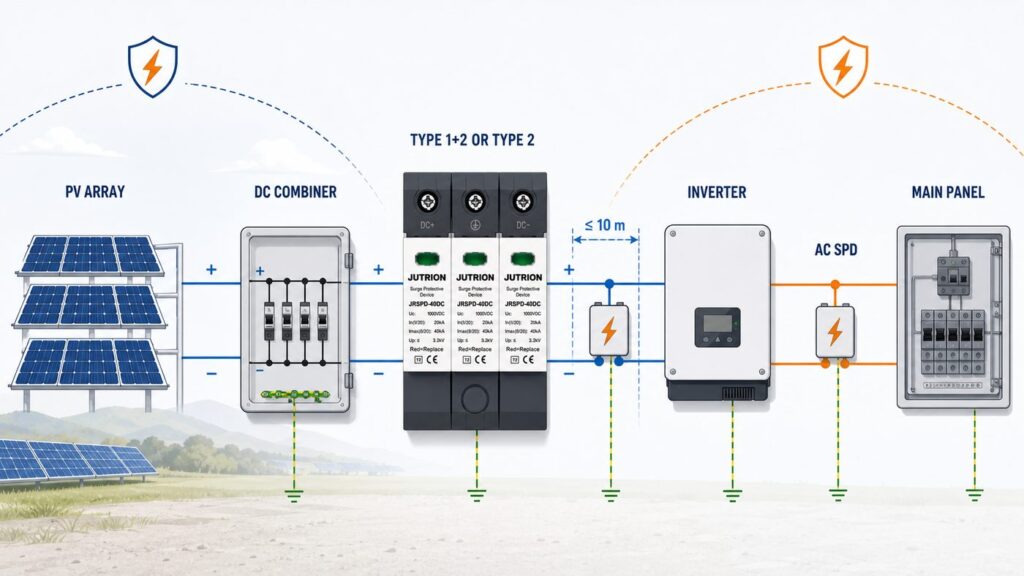
An SPD only protects what sits close to it, so location is part of the specification, not an afterthought.
- At the inverter DC input — unless the inverter already contains a coordinated DC SPD. This is the equipment you are protecting.
- At the array or combiner box — when the DC cable run between array and inverter exceeds roughly 10 metres. Beyond that distance a surge induced on the long DC cable can build enough voltage that one SPD at the far end no longer protects both ends, so protect at both.
- At the combiner and recombiner boxes — on multi-string and large ground-mount systems, one SPD per string group plus the DC disconnect, following the array’s protection zones.
Two installation rules then decide how much voltage actually reaches the equipment:
- The 0.5 m rule. Keep the total connecting-lead length — the loop through the live poles and the earth conductor — to about 0.5 m. Every extra length of lead adds inductive voltage (V = L × di/dt) on top of the device’s Up during a fast surge, so neat cabling routed the long way round the enclosure quietly raises the let-through voltage. Take the shortest path to the busbar and the earth bar.
- Connect earth first. Establish the protective-earth path before the live conductors so the discharge path exists from the moment the SPD is live.
Read the datasheet: a PV DC SPD parameter decoder
A specification is only safe once you can read the datasheet without guessing. These are the lines that matter on a PV DC SPD, and what each one is telling you.
| Datasheet line | What it means | What to check |
|---|---|---|
| Ucpv (Uc DC) | Maximum continuous DC operating voltage | ≥ 1.2 × array maximum Voc, per mode of protection |
| Type / Class | Type 2 (Class II) or Type 1+2 (Class I+II) | Matches the lightning-exposure decision |
| Iimp (10/350 µs) | Partial-lightning impulse current, Type 1 test | Present and adequate only where Type 1+2 is required |
| In (8/20 µs) | Nominal discharge current, repeated duty | Sized to site exposure; the working rating |
| Imax (8/20 µs) | Maximum single discharge current | Comfortable margin above expected surge |
| Up | Voltage protection level (let-through) | ≥ 20 % below the inverter DC withstand voltage |
| Iscpv / SCCR | Short-circuit withstand at the terminals | ≥ array maximum short-circuit current at that point |
| Response time (tA) | How fast the element clamps | Nanosecond-order for MOV-based devices |
| Thermal disconnector / indicator | Internal fail-safe and status window | Present; green/red or flag indication; pluggable module preferred |
| Remote signaling contact | Volt-free contact for monitoring | Specify on large or unattended plants |
| Operating temperature / IP | Environmental range and ingress rating | Suits the combiner-box climate and enclosure |
| Poles / mounting / terminals | 2-pole or Y, 35 mm DIN rail, conductor capacity | Matches earthing arrangement and cable size |
If any of these lines is missing from a datasheet — particularly Ucpv, Iscpv, or the thermal disconnector — treat the omission as a reason to ask, not an assumption to make. A device that will not state its short-circuit withstand or its DC voltage rating is not documented for the DC side.
Don’t forget the AC side: protecting the whole PV system
A PV surge-protection specification that stops at the DC side is only half a specification. The same lightning or switching event that threatens the array reaches the inverter’s AC output and the point of connection to the building or grid, and that side needs its own SPD to IEC 61643-11 — an AC device, sized to the AC system voltage (for example Uc around 275 V line-to-earth on a 230/400 V system), not a DC device.
Coordinate the two sides: a Type 2 AC SPD at the inverter output and main AC board for a building with no external LPS, or a Type 1+2 AC SPD at the origin where an LPS is present, mirroring the logic used on the DC side. JUTRION’s AC range — the JUSPD-40AC (Type 2) and JUSPD-12.5AC (Type 1+2) — covers this side to the same standards, so a single supplier can provide a coordinated DC-and-AC set rather than two unmatched halves.
Monitoring, maintenance, and replacement
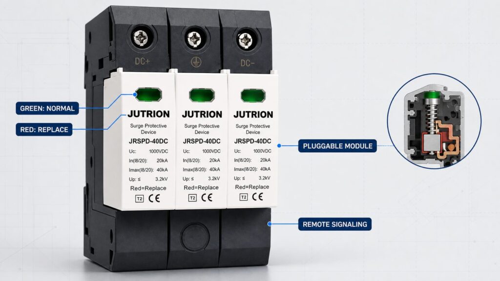
An SPD is a wear part. Every surge it diverts consumes a little of the varistor’s life, and the device is designed to reach end of life and disconnect rather than fail catastrophically. Specifying for that lifecycle is part of selection, not a separate maintenance topic.
- Pluggable modules. Prefer a device with a pluggable protection module and a base that stays wired in. Replacement then takes seconds and does not disturb the DC terminations or the earth path — important on a live PV system that cannot simply be switched off in daylight.
- Status indication. A mechanical flag or a green-to-red window shows at a glance whether the module still protects. On a large or roof-mounted array where no one inspects the combiner box weekly, add the remote signaling contact and wire it back to the monitoring system so an end-of-life module raises an alarm.
- Inspection and replacement. Check the indicators at each scheduled maintenance visit and after any known severe lightning event in the area. When the window shows red or the module has disconnected, replace the module — it no longer protects, even though the array keeps generating. Isolate safely and follow the manufacturer’s live-working guidance before removing a module on an energised DC system.
Designing the array’s protection so a failed module can be seen and swapped quickly is what keeps the protection real years after commissioning, rather than a green light everyone assumes is still green.
Worked example: a 100 kW commercial rooftop
The method comes together on a single realistic project. This case is illustrative, not a specific JUTRION installation, but the arithmetic is the arithmetic you would actually do.
The system. A 100 kWp flat commercial roof, 1500 V string inverters, no external lightning protection system on the building, moderate lightning-flash density. Modules: 550 W, Voc(STC) 49.9 V, Isc(STC) 13.85 A, temperature coefficient of Voc about −0.28 %/°C. Strings of 24 modules, four strings per combiner box, combiner boxes about 15 m of cable from the inverters.
- Voltage. String Voc(STC) = 24 × 49.9 = 1197.6 V. Ucpv ≥ 1.2 × 1197.6 = 1437 V → a 1500 V-class device. Cold check at a design minimum of −5 °C: +8.4 % on Voc ≈ 1298 V, still under 1500 V. The string length is safe for a 1500 V system; a 26-module string would have pushed Ucpv to ~1560 V and out of the 1500 V class.
- Type. No external LPS and a building roof → タイプ2 is correct at both the combiner and the inverter side. A Type 1+2 would be specified only if an LPS were added or the site were highly exposed.
- Short-circuit withstand. Per combiner, four parallel strings: Iscpv ≥ 1.25 × 13.85 × 4 ≈ 69 A. Choose a device whose Iscpv clears 69 A; most will, so no external backup fuse is needed — confirm on the datasheet.
- Locations and coordination. The 15 m run exceeds 10 m, so protect both the combiner boxes and the inverter DC input; the 15 m of cable also provides the decoupling that keeps the two stages energy-coordinated. First, though, check whether the inverters already contain an integrated DC SPD — if they do, keep the combiner-box devices and skip the redundant inverter-input ones.
- Up and earthing. Confirm each device’s Up sits at least 20 % below the inverter’s DC withstand voltage, and earth each SPD with at least 6 mm² copper bonded to the array frame and main earth.
- AC side. Add a Type 2 AC SPD at the inverter AC output / main LV board, Uc about 275 V, to IEC 61643-11.
Result: Type 2, 1500 V-class DC SPDs with Iscpv ≥ ~70 A at each combiner box and (if the inverter has no integrated device) at each inverter DC input, remote signaling on the combiner units for roof-level monitoring, plus a Type 2 AC SPD at the AC board. That is a coordinated, documented specification — not a box picked on discharge current alone.
Selection matrix: from PV system to a specified DC SPD
The matrix below turns the four inputs into a first-pass specification. Read across from the system and its exposure to the type, voltage class, discharge rating, and where the device belongs. Confirm the exact figures against the array calculation and the SPD datasheet before ordering.
| PV system and exposure | SPD type | Ucpv class | 放電定格 | Location |
|---|---|---|---|---|
| Residential rooftop, no external LPS | タイプ2 | Match system (600 / 1000 V) | In sized to exposure; Imax with margin | Inverter DC input; add array end if run > ~10 m |
| Commercial rooftop, no external LPS | タイプ2 | 1000 / 1500 V | Higher In for repeated duty | Inverter DC input and combiner box |
| Commercial rooftop with LPS present | タイプ 1+2 | 1000 / 1500 V | Iimp (10/350 µs) plus In/Imax | Inverter DC input and combiner box |
| Exposed ground-mount / hilltop / high flash density | タイプ 1+2 | 1500 V | Iimp rated for partial lightning current | Combiner and recombiner boxes; inverter DC input |
| Utility-scale free-field array | タイプ 1+2 | 1500 V | High Iimp and In; remote signaling | Every combiner/recombiner and inverter station, per protection zones |
Notice what the matrix does not include: a battery or energy-storage DC bus. IEC 61643-31 and IEC 61643-32 cover the PV generator and inverter DC side up to 1500 V DC; they explicitly do not cover PV systems with energy storage. A battery DC bus needs its surge protection assessed under its own requirements, so do not assume a PV-string SPD is a drop-in for the storage side — specify that separately.
The mistakes that undersize or void a PV DC SPD
Most failed or ineffective PV surge protection traces back to a short list of avoidable errors. Each one has a direct consequence.
- Using an AC SPD on the DC side. No DC-capable disconnector, wrong voltage basis — a fire risk, not a protection device.
- Sizing Ucpv to the nominal voltage. Ignoring the cold-morning Voc rise overstresses the device and trips its thermal disconnector early. Always size to 1.2 × the maximum Voc.
- Over-long or oversized strings. A string whose Voc pushes Ucpv past the 1500 V class leaves no compliant SPD; fix it at design time by shortening the string.
- Ignoring Iscpv. An SPD with a short-circuit withstand below the array’s fault current can fail violently instead of disconnecting cleanly.
- Leads too long. Exceeding the 0.5 m connecting-lead target adds inductive voltage and defeats a low Up.
- Doubling up on an integrated SPD. Fitting an external device beside the inverter’s own coordinated SPD protects nothing new and adds a failure point — put the effort at the unprotected array end.
- Uncoordinated stages. Two SPDs with no decoupling distance or defined inductor can leave the downstream device overstressed. Keep ~10 m between stages or follow the maker’s coordination data.
- No monitoring on unattended arrays. A red window on a rooftop combiner box no one opens means months of unprotected operation; specify the remote contact.
Turn the selection into an RFQ line
A selection is only useful once it becomes something a supplier can quote against without a second round of questions. The reader job at the end of this process is a single, unambiguous specification line. Capture these fields and an enquiry can be answered in one reply:
- Application and standard: PV DC side, to IEC 61643-31; state Type 2 or Type 1+2.
- System voltage class and Ucpv: the 600 / 1000 / 1500 V class and the minimum Ucpv from the 1.2 × Voc calculation.
- Array maximum Voc: the figure Ucpv was sized against, so the supplier can verify the margin.
- Discharge rating: required In and Imax (8/20 µs), and Iimp (10/350 µs) for a Type 1+2 device.
- Voltage protection level: the maximum acceptable Up, derived from the inverter’s DC withstand voltage.
- Short-circuit withstand: the minimum Iscpv from the array short-circuit calculation, and whether an external backup device is expected.
- Configuration and poles: standard 2-pole or Y-configuration, matched to the earthing arrangement.
- Installation point and monitoring: inverter input, combiner, or recombiner; DIN-rail format; and whether a remote signaling contact is required.
That line removes the guesswork on both sides and is the difference between a quote and a conversation.
Recommended DC SPD by project type
Bringing the method back to real decisions, here is how the specification typically lands for four common projects, mapped to the two JUTRION solar DC series — JRSPD-40DC-II (Type 2) and JRSPD-40DC-I+II (Type 1+2), both to IEC 61643-31, up to DC 1500 V, 40 kA Imax.
- Residential rooftop string inverter (no LPS): a Type 2 device (JRSPD-40DC-II class) at the inverter DC input, Ucpv matched to the string’s cold-morning Voc, sized for occasional induced surges. Add a second at the array end only if the DC run is long.
- Commercial rooftop (no LPS): Type 2 at both the combiner box and the inverter DC input, a higher nominal discharge current for repeated duty, and Up checked against the inverter’s DC withstand.
- Exposed ground-mount or utility array: Type 1+2 (JRSPD-40DC-I+II class) with a real Iimp rating at combiner and recombiner boxes, 1500 V class, and a remote signaling contact for plant monitoring — this is where the partial-lightning-current capability earns its cost.
- Array with a lightning protection system: Type 1+2 wherever separation distance to down-conductors cannot be maintained, coordinated with the LPS design rather than chosen in isolation.
Specify the four inputs first, size Ucpv to 1.2 × the real maximum Voc, choose the type from lightning exposure, then confirm Up, short-circuit withstand, the thermal disconnector, configuration, and earthing against the datasheet. If you want those figures checked against a specific array before you order, the JUTRION AC & DC surge protective device range lists the DC series with the ratings this guide asks for, and the engineering team can confirm the match for your string voltage and site exposure.
References
- IEC 61643-31:2018 — Low-voltage surge protective devices, Part 31: Requirements and test methods for SPDs for photovoltaic installations.
- IEC 61643-32:2017 — Low-voltage surge protective devices, Part 32: SPDs connected to the DC side of photovoltaic installations, selection and application principles.
- IEC 62305 series — Protection against lightning (risk assessment and lightning protection system coordination).
- IEC 62548 — Photovoltaic (PV) arrays: design requirements (basis for array maximum short-circuit current).
- IEC 60364-5-53 — Low-voltage electrical installations: selection and erection of electrical equipment, isolation, switching and control (SPD connection and conductor sizing).
