

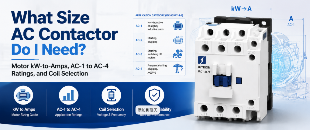
Szybka odpowiedź: Co robi stycznik AC?
Stycznik AC to sterowany elektrycznie przełącznik, który wykorzystuje elektromagnes napędzany cewką do zamykania i otwierania obwodu mocy na polecenie, a jest zbudowany tak, aby robić to od tysięcy do milionów razy bez zgrzewania się lub zużywania styków. Przełącza prąd obciążenia, gdy otrzyma polecenie. Nie chroni obwodu. Prawidłowe dobranie go oznacza dobranie go do wartości znamionowej odpowiadającej rzeczywistemu charakterowi obciążenia, a nie do najwyższej liczby wydrukowanej na etykiecie.
Stycznik oznaczony 20 A nie jest urządzeniem 20 A dla silnika. Ta sama jednostka fizyczna może mieć wartość znamionową 20 A dla grzałki rezystancyjnej i 9 A dla silnika klatkowego, ponieważ prąd rozruchowy silnika i przerywanie obciążenia indukcyjnego obciążają styki znacznie bardziej niż grzałka. To jedno rozróżnienie powoduje więcej przedwczesnych awarii styczników niż jakikolwiek inny błąd doboru.
Ten przewodnik obejmuje to, co stycznik musi przenosić, jak to obliczyć, która kategoria użytkowania ma zastosowanie oraz kontrole biegunów, cewki, styków pomocniczych, trwałości i koordynacji, które następują po wartości prądu.
Dopasuj zadanie łączeniowe do właściwego urządzenia
Zanim cokolwiek dobierzesz, potwierdź, że stycznik jest właściwym urządzeniem do danego zadania. Projekty szaf sterowniczych często zawodzą, ponieważ od jednego komponentu oczekuje się pełnienia dwóch niepowiązanych funkcji.
| Urządzenie | Główne zadanie | Częstotliwość łączeń | Wyzwala przy zwarciu |
|---|---|---|---|
| Stycznik AC | Zamykanie i otwieranie prądu obciążenia na polecenie | Zaprojektowany do częstego cyklicznego przełączania | Nie. Wymaga oddzielnego przekaźnika przeciążeniowego lub wyłącznika |
| Przekaźnik ogólnego przeznaczenia | Przełączanie małej mocy i sterowanie sygnałami | Przystosowany do lżejszych warunków pracy | Nie |
| MCB lub MCCB | Ochrona nadprądowa i zwarciowa | Sporadyczne działanie, nie rutynowe cykliczne przełączanie | Tak |
| Rozrusznik silnikowy | Stycznik i przekaźnik przeciążeniowy w jednym zespole | Taki sam jak stycznik | Tak, przez przekaźnik przeciążeniowy |
| Softstart lub przemiennik częstotliwości | Kontrolowany rozruch prądu silnika | Sterowanie ciągłe, a nie włącz/wyłącz | Zależy od modelu |
Jeśli pytanie brzmi, jak wielokrotnie włączać i wyłączać obciążenie na polecenie, odpowiedzią jest stycznik. Jeśli pytanie brzmi, co chroni obwód przed przeciążeniem, to jest to inne urządzenie. Traktowanie stycznika tak, jakby robił jedno i drugie, to jeden z najczęstszych błędów w projektowaniu szaf sterowniczych.
Dlaczego przekaźnik lub wyłącznik nie może go zastąpić
Przekaźnik ogólnego przeznaczenia może zamknąć obwód, ale nie jest zbudowany do robienia tego przy poziomach prądu silnika lub grzałki w dłuższej perspektywie. Styczniki mają trwałość mechaniczną rzędu milionów operacji, podczas gdy przekaźniki ogólnego przeznaczenia mają znamionową trwałość stanowiącą niewielki ułamek tego przy rzeczywistym obciążeniu elektrycznym. Różnica leży w materiale styków, sile sprężyny i gaszeniu łuku. Styczniki wykorzystują geometrię styków, a w większych obudowach komory gaszeniowe potrzebne do wielokrotnego przerywania indukcyjnego prądu silnika bez wżerów i zgrzewania styków. Przekaźnik zmuszony do takiej pracy zwykle ulega awarii przez zgrzanie styków w pozycji zamkniętej pod obciążeniem, co jest znacznie gorszym trybem awarii niż stopniowe zużycie stycznika.
Wyłącznik nadprądowy jest zaprojektowany do ochrony obwodu i do sporadycznego działania, a nie do cyklicznego przełączania w ramach normalnej logiki automatyki. Używanie wyłącznika jako łącznika roboczego skraca jego trwałość ochronną i nie jest tym, do czego ma wartości znamionowe. Stycznik i urządzenie ochronne pełnią dwie różne funkcje i powinny znajdować się w tym samym obwodzie razem.
Jak działa stycznik AC
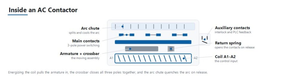
Sekwencja działania wyjaśnia większość trybów awarii omówionych w dalszej części tego przewodnika.
- Sygnał sterujący zasila cewkę. Obwód sterowania, taki jak wyjście PLC, termostat lub logika przyciskowa, podaje napięcie na cewkę przy jej znamionowym napięciu cewki.
- Elektromagnes przyciąga zworę. Zasilona cewka wytwarza pole magnetyczne, które przyciąga ruchomą zworę w kierunku nieruchomego rdzenia.
- Styki główne zamykają się. Ruch zwory zamyka główne styki mocy poprzez wspólną poprzeczkę, łącząc obciążenie z zasilaniem.
- Styki pomocnicze zmieniają stan. Małe styki pomocnicze połączone z tą samą zworą otwierają się lub zamykają równocześnie ze stykami głównymi. Zapewniają one blokadę, sygnalizację i potwierdzenie dla PLC, że stycznik faktycznie się zamknął.
- Siła sprężyny utrzymuje docisk styków. Stabilny docisk styków pod wpływem wibracji i obciążenia zapobiega odbijaniu styków i nagrzewaniu rezystancyjnemu na powierzchni styku.
- Odłączenie zasilania cewki otwiera obwód. Gdy sygnał sterujący zanika, pole magnetyczne zapada się, a sprężyna powrotna odciąga zworę z powrotem, otwierając styki główne.
- Tłumienie łuku obsługuje przerwanie. Otwieranie obwodu pod obciążeniem, zwłaszcza indukcyjnym obciążeniem silnikowym, wywołuje łuk elektryczny między rozdzielającymi się stykami. Geometria styków i komory gaszeniowe gaszą ten łuk wystarczająco szybko, aby zapobiec uszkodzeniom w każdym cyklu.
Kategorie użytkowania decydują o rzeczywistym prądzie znamionowym
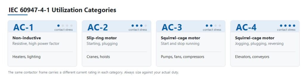
IEC 60947-4-1 definiuje kategorie użytkowania, które opisują, jak trudne dla styków jest dane obciążenie, a nie po prostu ile amperów pobiera. To krok, do którego sprowadza się większość błędów doboru.
| Kategoria | Typ obciążenia | Charakter pracy łączeniowej | Typowe zastosowanie |
|---|---|---|---|
| AC-1 | Nieindukcyjne lub lekko indukcyjne, wysoki współczynnik mocy | Brak znaczącego prądu rozruchowego | Grzejniki rezystancyjne, baterie grzewcze HVAC, oświetlenie ogólne |
| AC-2 | Silniki pierścieniowe (z wirnikiem uzwojonym) | Rozruch i hamowanie przeciwprądem pod obciążeniem | Żurawie, wciągniki |
| AC-3 | Silniki klatkowe | Rozruch i wyłączanie pracującego silnika | Pompy, wentylatory, sprężarki |
| AC-4 | Silniki klatkowe | Praca impulsowa, hamowanie przeciwprądem, szybkie nawroty | Windy, przenośniki, obrabiarki |
Konsekwencją jest to, że pojedynczy stycznik ma kilka różnych wartości prądu znamionowego. Stycznik JUTRION JRC1-D09 ma znamionowe 20 A w kategorii AC-1 i 9 A w kategorii AC-3. Obie wartości opisują to samo urządzenie fizyczne. Dobieranie pompy według wartości 20 A stawia stycznik na ponad dwukrotność jego wartości znamionowej dla pracy silnikowej, a styki to pokażą.
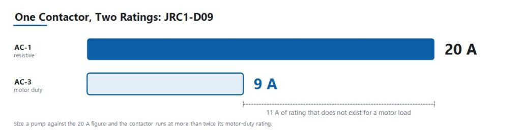
Każdą opublikowaną wartość znamionową należy odczytywać razem z kategorią, do której należy. Korpus to nie model dźwigu ani model pracy impulsowej. To jeden korpus z kilkoma wartościami znamionowymi, a charakter pracy decyduje, która wartość ma zastosowanie w projekcie.
Przelicz dane silnika na ampery
Użyj zweryfikowanego prądu pełnego obciążenia bezpośrednio, gdy projekt już go podaje. Gdy dane podane są jako moc silnika, przelicz je przy użyciu prawidłowego napięcia i układu faz.
Silniki trójfazowe
I = P × 1 000 / (√3 × VLL × cos φ × η)
Obciążenia jednofazowe
I = P × 1 000 / (V × cos φ × η)
Gdzie, I to prąd przewodowy w amperach, P to znamionowa moc wyjściowa silnika w kW, VLL to trójfazowe napięcie międzyprzewodowe, V to napięcie jednofazowe, cos φ to współczynnik mocy, a η to sprawność.
Współczynnik mocy standardowych silników indukcyjnych zwykle mieści się między 0,80 a 0,88, a sprawność między 0,85 a 0,93 w zależności od klasy sprawności. Używaj wartości z tabliczki znamionowej, gdy tylko są dostępne. Typowe zakresy służą do prac wstępnych przed otrzymaniem karty katalogowej silnika.
Dla czysto rezystancyjnych obciążeń jednofazowych, takich jak elementy grzejne, współczynnik mocy i sprawność są w praktyce równe jedności, a wyrażenie upraszcza się do I = P × 1 000 / V.
Kategoria JUTRION AC contactor sizing calculator performs the same calculation and returns a minimum AC-3 operational current. It is a starting point for the specification, not a substitute for the motor nameplate or the manufacturer’s rating tables.
Apply the Load-Type Multipliers and Ambient Derating
Certain loads draw far more than their steady-state current at the moment of switching. Long-standing industry practice applies a multiplier to account for that behaviour. These conventions are not values defined in IEC 60947-4-1, so treat them as a first pass and confirm them against actual inrush data for critical or large circuits.
| Typ obciążenia | Conventional multiplier | Reason |
|---|---|---|
| Capacitor banks | Approximately 1.5 × capacitor rated current | Capacitive inrush at switch-on is severe and very short |
| Transformers and welding sets | Approximately 2 × rated current | Magnetizing inrush can reach many times steady-state current |
| Gas-discharge and HID lighting | Approximately 1.1 to 1.4 × rated current | Ballast inrush and warm-up behaviour |
| Poor cooling or densely packed enclosure | 110 to 120 percent of load rated current | Elevated internal temperature reduces current capacity |
| Continuously running motor, long duty | Contactor rated current reduced by approximately 30 percent | Sustained thermal loading of the contacts |
Ambient Temperature and Enclosure Conditions
A contactor’s rated current assumes the reference ambient temperature stated on its datasheet. Above that temperature, current-carrying capacity falls, but the derating slope is specific to the manufacturer and the frame. Use the derating curve from the actual product documentation rather than a generic percentage.
Two conditions apply regardless of product. First, base the calculation on the temperature inside the enclosure, not the room. A densely packed panel in a warm plant runs considerably hotter than ambient. Second, contactors mounted side by side with no spacing heat one another, so respect the manufacturer’s minimum spacing or derate further.
A Worked Example: 4 kW Pump Motor at 400 V
A three-phase centrifugal pump motor in an OEM water-treatment panel. Standard start and stop duty, approximately 20 starts per hour, panel ambient around 35 °C.
Step 1. Establish the utilization category. A squirrel-cage induction motor, started and stopped normally, is category AC-3. It is not AC-1, even though the load is described as a simple pump.
Step 2. Calculate full-load current. Nameplate values are 4 kW, 400 V, cos φ = 0.85, η = 0.90.
I = 4 × 1,000 / (1.732 × 400 × 0.85 × 0.90)
Working the denominator: 1.732 × 400 = 692.8, then × 0.85 = 588.9, then × 0.90 = 530.0.
I = 4,000 / 530.0 ≈ 7.6 A
Step 3. Select against the AC-3 rating. The requirement is a contactor whose AC-3 rating covers 7.6 A with margin. The JRC1-D09 is rated 9 A at AC-3, giving approximately 18 percent headroom over the calculated full-load current. Note what was not done: the same JRC1-D09 carries a 20 A AC-1 rating, and sizing this pump against that figure would have been the single most common contactor selection error.
Step 4. Check ambient and duty. At 35 °C panel ambient with 18 percent headroom, verify the figure against the product’s derating curve before committing. That margin is comfortable in a well-ventilated panel and tighter in a densely packed one. At 20 starts per hour, confirm that the rated operations per hour and the AC-3 electrical life comfortably exceed the expected duty across the panel’s service life.
Step 5. Specify coil voltage. The panel’s control transformer secondary is 220 V AC, so the coil is specified at 220 V. It is not 400 V, even though the motor runs at 400 V.
Step 6. Add protection. Pair the contactor with a correctly sized overload relay set to the motor’s full-load current, and confirm Type 1 or Type 2 coordination with the upstream breaker or fuse. A normal start under 10 seconds points to a Class 10 trip class here. The overload relay setting calculator converts nameplate current, service factor, and start duration into a preliminary setting and trip class.
Result: a JRC1-D09, three-pole, with a 220 V AC coil, plus an overload relay. The selection was derived from the load, not from a catalogue.
The same procedure applies at higher power. An 18.5 kW motor at 400 V works out to roughly 35 A full-load current and requires a contactor with an AC-3 rating above that figure.
Use This Seven-Step AC Contactor Selection Process
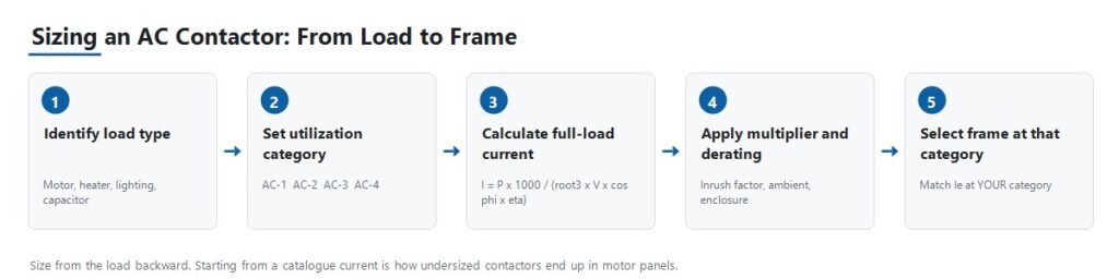
Step 1: Identify the Load Type and Utilization Category
Establish whether the load is resistive, a standard squirrel-cage motor, a wound-rotor motor starting under load, or a motor subject to jogging and reversing. Everything downstream depends on this answer, because it determines which of the contactor’s several current ratings actually applies.
Step 2: Calculate Operational Current and Confirm Voltage
Use the formulas above to obtain full-load current, apply the relevant load-type multiplier, then confirm that the contactor’s rated operational current Ie at your utilization category covers it with margin. Match the rated operational voltage Ue to the system line voltage.
Step 3: Select Coil Voltage
Coil voltage is a separate specification from load voltage. A 380 V motor circuit may be switched by a 24 V DC or 220 V AC coil depending on the control architecture. Confirm what the control circuit actually supplies, whether that is a PLC output, a control transformer secondary, or a DC control supply, before ordering.
Step 4: Choose Pole Count and Configuration
Three-pole is standard for three-phase motor loads. Four-pole is used where neutral switching or an additional independent circuit is required. Confirm the arrangement against the system earthing design, since neutral switching is required in some systems and unnecessary or prohibited in others.
Step 5: Specify Auxiliary Contacts
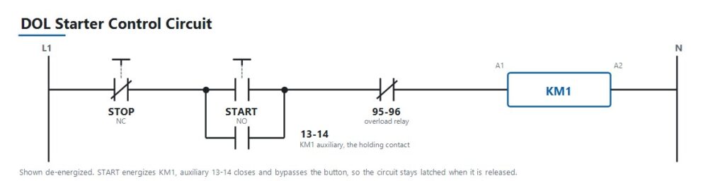
Determine how many normally open and normally closed auxiliary contacts are needed for interlocking, PLC status feedback, and indicator lamps, and whether they are integral or added as a separate auxiliary block. In a standard direct-on-line starter, an auxiliary contact wired in parallel with the start button is what latches the control circuit so the contactor stays energized after the operator releases the button. Auxiliary contacts are inexpensive to specify at design stage and awkward to retrofit afterwards.
Step 6: Check Electrical Life Against Actual Duty Cycle
For frequently cycling applications such as jogging, reversing, or high-frequency automation sequences, check the rated operations per hour and the electrical life at your utilization category. Mechanical life, measured without load, is always the higher and less relevant figure.
Step 7: Coordinate with Upstream Protection
Pair the contactor with a correctly sized overload relay for motor loads, then coordinate with an upstream breaker or fuse sized for short-circuit protection. On larger distribution boards that upstream device is often an air circuit breaker. Contactor selection is one link in a chain that runs from load current, to breaker rating, to prospective fault current, to device breaking duty. Getting the contactor right while leaving that chain unverified simply relocates the problem.
IEC 60947-4-1 and NEMA Ratings Are Not Interchangeable Labels
AC contactors sold internationally are generally built to IEC 60947-4-1, which defines the utilization categories and the rating structure used throughout this guide. The current fifth edition was published in 2023 and supersedes the 2018 edition. It is worth checking which edition a project specification references, because they are not identical.
North American markets commonly reference NEMA ICS 2 contactor ratings instead of, or alongside, IEC utilization categories. The two systems classify contactors differently, since NEMA uses size classes rather than AC-1 through AC-4. A specification written for one market does not translate automatically to the other. When sourcing for a North American project, confirm which framework the buyer’s specification actually requires before quoting a part.
Treat the product standard, the installation code, and any market-specific requirement as three separate questions. Confirming one does not answer the others.
Type 1 and Type 2 Coordination
Short-circuit coordination under IEC 60947-4-1 determines how much damage a fault causes to the contactor and starter. Type 1 permits damage to the equipment after a short-circuit fault, provided the damage is contained and no hazard results, and the equipment may require repair or replacement. Type 2 requires that the equipment remains suitable for further use, with only light contact welding permitted. These are different commercial and engineering outcomes. Confirm which one the project specification requires before selecting the combination.
Choosing Between the JUTRION JRC1 Ratings
JUTRION manufactures the JRC1 series AC contactor on its own production lines in Wenzhou, Zhejiang, built to IEC 60947-4-1. Coil voltage options include 24 V, 48 V, 110 V, 220 V, and 380 to 415 V at 50 or 60 Hz. Every unit is tested for mechanical operation, coil performance, and electrical switching before shipment.
The following are published rating points across the four utilization categories. Read the table by category rather than by model, since the same frame appears under more than one category with a different rating.
| Kategoria | Rating point | Duty this represents |
|---|---|---|
| AC-1 | JRC1-D09, 20 A | Grzejniki rezystancyjne, baterie grzewcze HVAC, oświetlenie ogólne |
| AC-2 | JRC1-D25, 25 A | Wound-rotor motors starting under load, cranes and hoists |
| AC-3 | JRC1-D09, 9 A | Squirrel-cage motors, normal start and stop, pumps and fans |
| AC-4 | JRC1-D18, 7.7 A | Jogging, plugging, rapid reversing, elevators and conveyors |
The JRC1-D09 appears twice, at 20 A under AC-1 and 9 A under AC-3, because those are two ratings of the same physical contactor under two different duties. For a standard induction-motor circuit, which covers the majority of pump, fan, and compressor applications, size against the AC-3 rating as shown in the worked example. For jogging or reversing duty, size against AC-4 instead, where the same frame carries substantially less current.
Frame ratings above these published points are available. Final model selection should be based on the model-specific ratings and project conditions, not on a current figure alone.
Apply the Selection Logic to Five Panel Scenarios
Standard Motor Panel for Pumps, Fans, and Compressors
An OEM building control panels for HVAC or water-treatment equipment specifies contactors for straightforward motor start and stop duty. This is category AC-3. Size the AC-3 rating against the calculated full-load current, pair it with a correctly sized overload relay, and match the coil voltage to the panel’s control transformer output.
Crane or Hoist Panel with Wound-Rotor Motors
A crane OEM requires contactors that handle high-torque starting and plugging duty on wound-rotor motors, which is category AC-2. These loads are harder on the contacts than standard AC-3 duty because of repeated starting under load and reversing. Undersizing here appears as premature contact wear rather than immediate failure, which makes it easy to misdiagnose as a quality problem.
Elevator or Conveyor Control with Jogging and Reversing
A machine builder needs contactors for an application with frequent direction reversal and inching moves, which is category AC-4, the most demanding of the four. Electrical life at the actual operations-per-hour rate matters more here than in any other scenario. Undersizing this category is the fastest way to consume a contactor’s rated life.
Capacitor Bank Switching for Power Factor Correction
A facility adding power-factor-correction capacitors needs contactors sized against capacitive inrush, conventionally about 1.5 times capacitor rated current, and frequently specified with pre-charging resistors or as dedicated capacitor-switching contactors. Standard AC-1 sizing is not adequate, because capacitive inrush is a distinct switching duty rather than a mild version of resistive duty.
Resistive Heating or Lighting Panel
A panel builder switching HVAC heating banks or large lighting loads is working in category AC-1, the least demanding, since there is no significant inrush or inductive kick to manage. Discharge and HID lighting are the exception and require the 1.1 to 1.4 multiplier for ballast inrush. This is also the case where buyers sometimes over-specify by choosing an AC-3-rated part where AC-1 would serve, which is not unsafe, only unnecessary cost.
Avoid the Nine Mistakes That Cause Early Contactor Failure
| Mistake | Consequence | Prevention |
|---|---|---|
| Sizing against the AC-1 rating for a motor load | Contactor undersized for its real duty, contacts weld or wear out early | Always size against the rating for the actual utilization category |
| Omitting the overload relay | Motor and contactor both exposed to sustained overcurrent | Pair every motor circuit with a correctly sized overload relay |
| Ignoring switching frequency against electrical life | A correctly current-sized contactor still fails early in high-cycle duty | Check rated operations per hour and electrical life at your category |
| Mismatched coil voltage | Contactor fails to pull in, or the coil burns out | Confirm against the actual control-circuit voltage, not the load voltage |
| No upstream coordination check | A short-circuit fault destroys the contactor unnecessarily | Verify Type 1 or Type 2 coordination before finalizing the design |
| Reversing contactors without interlocking | Both contactors can close together, creating a phase-to-phase short | Specify both mechanical and electrical interlocking on reversing pairs |
| Ignoring ambient temperature and enclosure derating | Shortened life despite every other specification being correct | Derate using the product curve and the enclosure temperature |
| Forgetting the load-type multiplier | Capacitor, transformer, or lighting inrush degrades contacts over time | Apply the conventional multiplier for the load type |
| Specifying auxiliary contacts too late | Costly panel rework or awkward add-on blocks | Determine interlocking and feedback needs at design stage |
Install, Commission, and Diagnose the Contactor
Most contactor faults reported as product defects are symptoms of a sizing, coordination, or control-supply problem. The table below maps the common symptoms to the checks that identify the cause.
| Symptom | Possible causes | Useful checks |
|---|---|---|
| Chatters or hums loudly | Low or unstable coil voltage, worn shading coil, dirty or loose magnetic core | Measure coil voltage under load, inspect the core face, verify control supply stability |
| Contacts welded shut | Undersized for the actual category, short-circuit event without adequate coordination, excessive switching frequency | Verify category sizing, review upstream fault history, compare operations per hour against rated electrical life |
| No pickup although the control signal is present | Open-circuit coil, wrong coil voltage, mechanical binding, blown control fuse | Measure coil resistance and voltage at the terminals, check the control fuse, inspect for obstruction |
| Contacts pitted or burned | Normal end-of-life wear, undersized for duty category, poor arc suppression at high switching frequency | Compare condition against rated electrical life, re-verify category sizing, inspect the arc chute |
| Auxiliary feedback disagrees with the main contact state | Worn or misaligned auxiliary block, mechanical linkage wear | Test auxiliary continuity independently, inspect the linkage to the main contact assembly |
| Terminals overheating | Loose termination, undersized conductor, incorrect torque at installation | Check terminal torque against specification, verify conductor sizing, thermal-image under load |
| Coil burns out repeatedly | Sustained overvoltage on the control circuit, excessive ambient temperature, mechanical binding preventing full pull-in | Measure control voltage under all operating conditions, check for binding, verify ambient temperature |
Repeated early failures in the same application almost always indicate a sizing, coordination, or duty-cycle mismatch rather than a defective batch. Diagnose the cause before re-ordering the same part number.
Protect the Coil and Whatever Drives It
De-energizing an inductive coil produces a voltage transient. When a PLC transistor output, a small interposing relay, or an electronic controller switches that coil directly, the transient travels back into it. This is a routine cause of PLC output failures and of pitted contacts on interposing relays, and it is straightforward to design out. Use an RC snubber across AC coils, and a flyback diode or varistor on DC coils. Note the trade-off: a plain flyback diode noticeably extends drop-out time, which matters when the contactor forms part of a safety-related stop function with a specified response time.
Confirm the coil’s operating voltage tolerance rather than assuming the nominal figure holds. A long control cable run or an undersized control transformer can put the actual coil voltage below the band in which the coil will pull in and hold, and the symptom appears as chattering rather than as an obvious wiring fault.
State These Parameters When Requesting a Quote
A contactor enquiry that includes the following information can be answered with a specific model in the first reply. An enquiry that gives only an ampere figure normally requires several rounds of clarification, because a bare current value does not identify the duty it applies to.
- Application or equipment being controlled
- Load type: motor, heater, lighting, capacitor, or transformer
- Utilization category, if already determined
- Motor rated power in kW, or load in kW
- System voltage and frequency
- Calculated full-load current
- Duty: starts per hour, and whether the application reverses or jogs
- Required coil voltage, and whether AC or DC
- Pole count, three-pole or four-pole
- Auxiliary contacts required, normally open and normally closed
- Upstream protective device, breaker or fuse
- Panel ambient temperature
- Mounting arrangement, DIN rail or screw
- Order quantity and destination market
- Any OEM or ODM requirements
Często zadawane pytania
Jaka jest różnica między stycznikiem AC a rozrusznikiem silnika?
Rozrusznik silnikowy to stycznik połączony z przekaźnikiem przeciążeniowym w jednym zespole, zapakowany specjalnie do obwodów silnikowych. Samodzielny stycznik zapewnia wyłącznie funkcję przełączania, a zabezpieczenie przeciążeniowe jest dodawane osobno.
Czy jeden stycznik może być używany zarówno do obciążeń AC-1, jak i AC-3?
The same physical contactor is usually rated for several categories, but at a different current rating for each. Size against the rating that matches the actual load’s utilization category, not the highest number on the label.
Jak obliczyć prąd do doboru stycznika?
For a three-phase motor, use I = P × 1,000 / (√3 × VLL × cos φ × η), where P is rated power in kW, VLL is line-to-line voltage, cos φ is power factor, and η is efficiency. Then apply any load-type multiplier and confirm the result against the contactor’s rating at your utilization category.
Czy większy stycznik jest zawsze bezpieczniejszy?
No. Oversizing wastes cost and panel space, and on some loads an oversized contactor’s contacts carry too little current to stay clean. Size with sensible margin over the calculated full-load current at the correct category rather than jumping two frame sizes.
Jakie napięcie cewki powinienem wybrać?
Dopasuj to do tego, co faktycznie dostarcza obwód sterowania, niezależnie od tego, czy jest to wyjście PLC, uzwojenie wtórne transformatora sterowniczego, czy zasilanie panelu DC. To nie jest napięcie po stronie obciążenia, które przełącza stycznik.
Dlaczego mój stycznik buczy lub terkocze?
Typowymi przyczynami są niskie, niestabilne lub nieprawidłowe napięcie cewki albo zużyta lub zabrudzona powierzchnia rdzenia magnetycznego w urządzeniu z cewką prądu przemiennego. Zmierz napięcie cewki w rzeczywistych warunkach obciążenia i sprawdź powierzchnię rdzenia, zanim uznasz urządzenie za wadliwe.
Czy nadal potrzebuję przekaźnika przeciążeniowego, jeśli używam stycznika?
Yes, for motor circuits. A contactor switches on command but does not trip on sustained overcurrent, which is the overload relay’s function. The two devices work together and do not substitute for one another.
How many switching cycles can a contactor handle?
It depends on the frame size and, more importantly, on the utilization category and current level at which it operates. Mechanical life measured without load is typically far higher than electrical life under load, and electrical life falls further at higher switching frequencies. Check the rated electrical life at the actual duty cycle.
Can two contactors be wired in parallel to share current?
This is generally not recommended for main load switching. Contacts never close at exactly the same instant, so one device carries the full making current. Use a correctly sized single contactor instead.
What is the difference between Type 1 and Type 2 coordination?
Under IEC 60947-4-1, Type 1 permits damage to the contactor and starter after a short-circuit fault provided the damage is contained and no hazard results. Type 2 requires that the equipment remains suitable for further use, with only light contact welding permitted. Confirm which the project specification requires.
Do I need to derate the contactor for high ambient temperature?
Yes. The rated current assumes a datasheet reference ambient. Above that temperature, capacity falls. Use the manufacturer’s derating curve and base it on the temperature inside the enclosure rather than the room temperature.
How do I test an AC contactor with a multimeter?
With the circuit isolated and locked off, measure coil resistance across A1 and A2. An open circuit or a near-zero reading indicates a failed coil. Then check continuity across each main pole, which should read open when de-energized and closed when the contactor is pressed in manually. Compare all three poles, since one pole reading noticeably differently points to contact damage on that pole.
Size From the Load, Not From the Catalogue
A reliable contactor selection is derived from what the application demands and works forward to a part number. Starting from an available frame size and hoping the duty fits is how undersized contactors end up in motor panels.
The practical order is straightforward: define the load and its utilization category, calculate the full-load current, apply the load-type multiplier and ambient derating, then verify the contactor’s rated operational current at that category. Only after the ampere figure is settled do the pole, coil, auxiliary contact, electrical life, and short-circuit coordination checks complete the specification.
Once those inputs are confirmed, compare them against the available configurations in the JUTRION AC contactor range. Final model selection should follow the model-specific ratings and the project conditions, not the current figure alone.
