

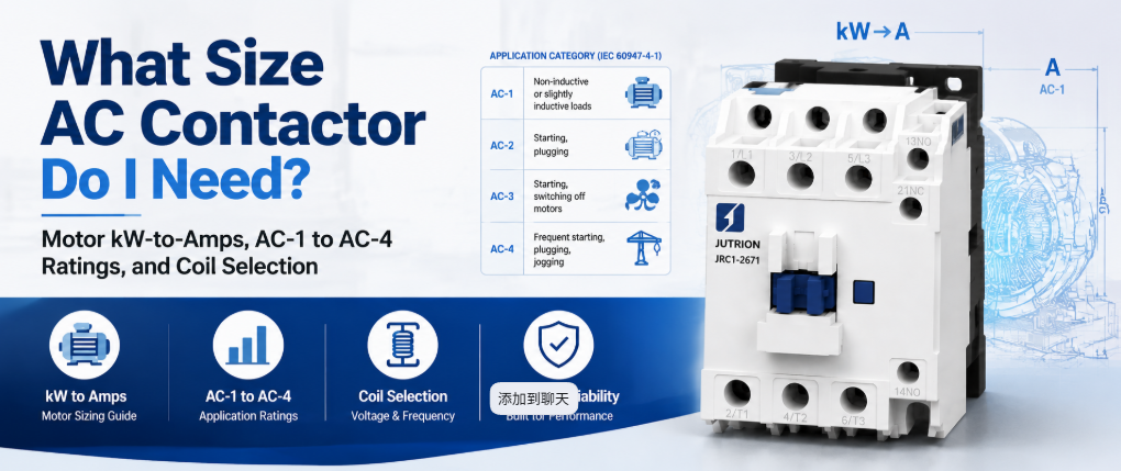
Réponse rapide : À quoi sert un contacteur CA ?
Un contacteur CA est un interrupteur à commande électrique qui utilise un électroaimant actionné par une bobine pour établir et couper un circuit de puissance sur commande, et il est conçu pour le faire des milliers, voire des millions de fois, sans que les contacts ne se soudent ou ne s'usent. Il commute le courant de charge lorsqu'on le lui demande. Il ne protège pas le circuit. Le dimensionner correctement signifie le dimensionner en fonction du calibre qui s'applique à votre service de charge réel, et non au chiffre le plus élevé imprimé sur l'étiquette.
Un contacteur marqué 20 A n'est pas un appareil de 20 A pour un moteur. La même unité physique peut être calibrée à 20 A pour un radiateur résistif et à 9 A pour un moteur à cage d'écureuil, car le courant d'appel du moteur et la coupure inductive sollicitent les contacts bien plus durement qu'un radiateur. Cette seule distinction provoque plus de défaillances précoces de contacteurs que toute autre erreur de sélection.
Ce guide couvre ce que le contacteur doit supporter, comment le calculer, quelle catégorie d'emploi s'applique, ainsi que les vérifications des pôles, de la bobine, des auxiliaires, de la durée de vie et de la coordination qui suivent le chiffre en ampères.
Faire correspondre la tâche de commutation au bon appareil
Avant de dimensionner quoi que ce soit, confirmez qu'un contacteur est le bon appareil pour la tâche. Les conceptions de panneaux échouent souvent parce qu'on attend d'un seul composant qu'il remplisse deux fonctions sans rapport entre elles.
| Appareil | Tâche principale | Fréquence de commutation | Déclenchement sur défaut |
|---|---|---|---|
| Contacteur AC | Établit et coupe le courant de charge sur commande | Conçu pour des cycles fréquents | Non. Nécessite un relais de surcharge ou un disjoncteur séparé |
| Relais universel | Commutation de faible puissance et contrôle de signaux | Calibré pour un service plus léger | Non |
| MCB ou MCCB | Protection contre les surintensités et les courts-circuits | Fonctionnement occasionnel, pas de cycles de routine | Oui |
| Démarreur de moteur | Contacteur et relais de surcharge en un seul ensemble | Identique au contacteur | Oui, via le relais de surcharge |
| Démarreur progressif ou VFD | Rampe contrôlée du courant du moteur | Contrôle continu plutôt que marche/arrêt | Varie selon le modèle |
Si la question est de savoir comment commuter une charge en marche et en arrêt de manière répétée sur commande, la réponse est un contacteur. Si la question est de savoir ce qui protège le circuit contre la surcharge, c'est un autre appareil. Traiter le contacteur comme s'il faisait les deux est l'une des erreurs de conception de panneau les plus courantes.
Pourquoi un relais ou un disjoncteur ne peut pas le remplacer
Un relais universel peut fermer un circuit, mais il n'est pas conçu pour le faire à des niveaux de courant de moteur ou de radiateur sur le long terme. Les contacteurs sont calibrés pour une durée de vie mécanique de plusieurs millions de manœuvres, tandis que les relais universels sont calibrés pour une petite fraction de cela sous une charge électrique réelle. La différence réside dans le matériau des contacts, la force du ressort et la suppression de l'arc. Les contacteurs utilisent la géométrie des contacts et, sur les châssis plus grands, les chambres de coupure nécessaires pour couper le courant inductif du moteur de manière répétée sans que les contacts ne se piquent ou ne se soudent. Un relais poussé dans ce service échoue généralement en se soudant fermé sous charge, ce qui est un mode de défaillance bien pire que l'usure progressive d'un contacteur.
Un disjoncteur est conçu pour protéger un circuit et pour être actionné occasionnellement, pas pour être cyclé dans le cadre d'une logique d'automatisation normale. Utiliser un disjoncteur comme interrupteur de service raccourcit sa durée de vie de protection et ne correspond pas à son calibre. Le contacteur et le dispositif de protection remplissent deux tâches différentes et appartiennent ensemble au même circuit.
Comment fonctionne un contacteur CA
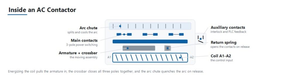
La séquence de fonctionnement explique la plupart des modes de défaillance abordés plus loin dans ce guide.
- Le signal de commande excite la bobine. Un circuit de commande, tel qu'une sortie d'automate, un thermostat ou une logique à boutons-poussoirs, applique une tension à la bobine à sa tension nominale.
- L'électroaimant attire l'armature. La bobine excitée crée un champ magnétique qui attire une armature mobile vers un noyau fixe.
- Les contacts principaux se ferment. Le mouvement de l'armature ferme les contacts de puissance principaux par l'intermédiaire d'une traverse commune, reliant la charge à l'alimentation.
- Les contacts auxiliaires changent d'état. De petits contacts auxiliaires liés à la même armature s'ouvrent ou se ferment en même temps que les contacts principaux. Ils assurent le verrouillage, la signalisation et la confirmation à un automate que le contacteur s'est effectivement fermé.
- La force du ressort maintient la pression de contact. Une pression de contact stable sous vibrations et en charge est ce qui empêche le rebond des contacts et l'échauffement résistif au niveau de la face de contact.
- La désexcitation de la bobine ouvre le circuit. Lorsque le signal de commande disparaît, le champ magnétique s'effondre et un ressort de rappel ramène l'armature en arrière, ouvrant les contacts principaux.
- La suppression de l'arc gère l'interruption. Ouvrir un circuit en charge, surtout une charge de moteur inductive, produit un arc entre les contacts qui se séparent. La géométrie des contacts et les chambres de coupure éteignent cet arc assez rapidement pour éviter tout dommage à chaque cycle.
Les catégories d'emploi déterminent le courant assigné réel
La norme IEC 60947-4-1 définit des catégories d'emploi qui décrivent la sévérité d'une charge pour les contacts, et non simplement le nombre d'ampères qu'elle consomme. C'est l'étape à laquelle remontent la plupart des erreurs de sélection.
| Catégorie | Type de charge | Service de commutation | Application typique |
|---|---|---|---|
| AC-1 | Non inductif ou légèrement inductif, facteur de puissance élevé | Pas d'appel de courant significatif | Résistances de chauffage, batteries de chauffage CVC, éclairage général |
| AC-2 | Moteurs à bagues (rotor bobiné) | Démarrage et freinage par contre-courant en charge | Grues, palans |
| AC-3 | Moteurs à cage d'écureuil | Démarrage et coupure d'un moteur en marche | Pompes, ventilateurs, compresseurs |
| AC-4 | Moteurs à cage d'écureuil | Marche par à-coups, freinage par contre-courant, inversion rapide | Ascenseurs, convoyeurs, machines-outils |
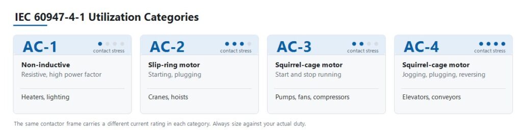
La conséquence est qu'un seul contacteur possède plusieurs courants assignés différents. Un JUTRION JRC1-D09 est assigné à 20 A en catégorie AC-1 et à 9 A en catégorie AC-3. Les deux chiffres décrivent le même appareil physique. Dimensionner une pompe sur la base des 20 A place le contacteur à plus du double de son courant assigné en service moteur, et les contacts le montreront.
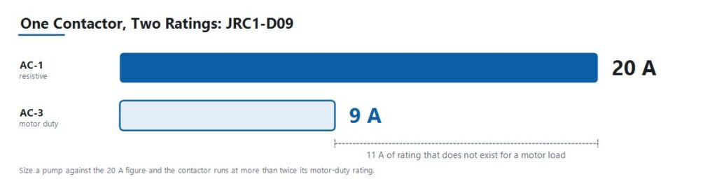
Lisez chaque courant assigné publié avec la catégorie à laquelle il appartient. Une taille de contacteur n'est pas un modèle pour grue ni un modèle pour marche par à-coups. C'est une seule taille avec plusieurs courants assignés, et le service détermine quel courant assigné s'applique au projet.
Convertir les données du moteur en ampères
Utilisez directement un courant à pleine charge vérifié lorsque le projet en fournit déjà un. Lorsque les données sont données en puissance moteur, convertissez-les en utilisant la tension et le montage de phases corrects.
Moteurs triphasés
I = P × 1 000 / (√3 × VLL × cos φ × η)
Charges monophasées
I = P × 1 000 / (V × cos φ × η)
Ici, I est le courant de ligne en ampères, P est la puissance assignée de sortie du moteur en kW, VLL est la tension triphasée entre phases, V est la tension monophasée, cos φ est le facteur de puissance, et η est le rendement.
Le facteur de puissance des moteurs à induction standard se situe généralement entre 0,80 et 0,88, et le rendement entre 0,85 et 0,93 selon la classe de rendement. Utilisez les valeurs de la plaque signalétique chaque fois qu'elles sont disponibles. Les plages typiques servent au travail préliminaire avant l'arrivée de la fiche technique du moteur.
Pour les charges monophasées purement résistives telles que les éléments chauffants, le facteur de puissance et le rendement sont effectivement unitaires, et l'expression se réduit à I = P × 1 000 / V.
La Le calculateur de dimensionnement de contacteur C.A. JUTRION effectue le même calcul et renvoie un courant opérationnel AC-3 minimal. C'est un point de départ pour la spécification, pas un substitut à la plaque signalétique du moteur ni aux tableaux de courants assignés du fabricant.
Appliquer les multiplicateurs selon le type de charge et le déclassement selon la température ambiante
Certaines charges consomment beaucoup plus que leur courant en régime établi au moment de la commutation. Une pratique industrielle de longue date applique un multiplicateur pour tenir compte de ce comportement. Ces conventions ne sont pas des valeurs définies dans la norme IEC 60947-4-1, alors traitez-les comme une première approximation et confirmez-les avec les données réelles d'appel de courant pour les circuits critiques ou de grande taille.
| Type de charge | Multiplicateur conventionnel | Raison |
|---|---|---|
| Batteries de condensateurs | Environ 1,5 × courant assigné du condensateur | L'appel de courant capacitif à la mise sous tension est sévère et très bref |
| Transformateurs et postes de soudage | Environ 2 × courant assigné | Magnetizing inrush can reach many times steady-state current |
| Gas-discharge and HID lighting | Approximately 1.1 to 1.4 × rated current | Ballast inrush and warm-up behaviour |
| Poor cooling or densely packed enclosure | 110 to 120 percent of load rated current | Elevated internal temperature reduces current capacity |
| Continuously running motor, long duty | Contactor rated current reduced by approximately 30 percent | Sustained thermal loading of the contacts |
Ambient Temperature and Enclosure Conditions
A contactor’s rated current assumes the reference ambient temperature stated on its datasheet. Above that temperature, current-carrying capacity falls, but the derating slope is specific to the manufacturer and the frame. Use the derating curve from the actual product documentation rather than a generic percentage.
Two conditions apply regardless of product. First, base the calculation on the temperature inside the enclosure, not the room. A densely packed panel in a warm plant runs considerably hotter than ambient. Second, contactors mounted side by side with no spacing heat one another, so respect the manufacturer’s minimum spacing or derate further.
A Worked Example: 4 kW Pump Motor at 400 V
A three-phase centrifugal pump motor in an OEM water-treatment panel. Standard start and stop duty, approximately 20 starts per hour, panel ambient around 35 °C.
Step 1. Establish the utilization category. A squirrel-cage induction motor, started and stopped normally, is category AC-3. It is not AC-1, even though the load is described as a simple pump.
Step 2. Calculate full-load current. Nameplate values are 4 kW, 400 V, cos φ = 0.85, η = 0.90.
I = 4 × 1,000 / (1.732 × 400 × 0.85 × 0.90)
Working the denominator: 1.732 × 400 = 692.8, then × 0.85 = 588.9, then × 0.90 = 530.0.
I = 4,000 / 530.0 ≈ 7.6 A
Step 3. Select against the AC-3 rating. The requirement is a contactor whose AC-3 rating covers 7.6 A with margin. The JRC1-D09 is rated 9 A at AC-3, giving approximately 18 percent headroom over the calculated full-load current. Note what was not done: the same JRC1-D09 carries a 20 A AC-1 rating, and sizing this pump against that figure would have been the single most common contactor selection error.
Step 4. Check ambient and duty. At 35 °C panel ambient with 18 percent headroom, verify the figure against the product’s derating curve before committing. That margin is comfortable in a well-ventilated panel and tighter in a densely packed one. At 20 starts per hour, confirm that the rated operations per hour and the AC-3 electrical life comfortably exceed the expected duty across the panel’s service life.
Step 5. Specify coil voltage. The panel’s control transformer secondary is 220 V AC, so the coil is specified at 220 V. It is not 400 V, even though the motor runs at 400 V.
Step 6. Add protection. Pair the contactor with a correctly sized overload relay set to the motor’s full-load current, and confirm Type 1 or Type 2 coordination with the upstream breaker or fuse. A normal start under 10 seconds points to a Class 10 trip class here. The overload relay setting calculator converts nameplate current, service factor, and start duration into a preliminary setting and trip class.
Result: a JRC1-D09, three-pole, with a 220 V AC coil, plus an overload relay. The selection was derived from the load, not from a catalogue.
The same procedure applies at higher power. An 18.5 kW motor at 400 V works out to roughly 35 A full-load current and requires a contactor with an AC-3 rating above that figure.
Use This Seven-Step AC Contactor Selection Process
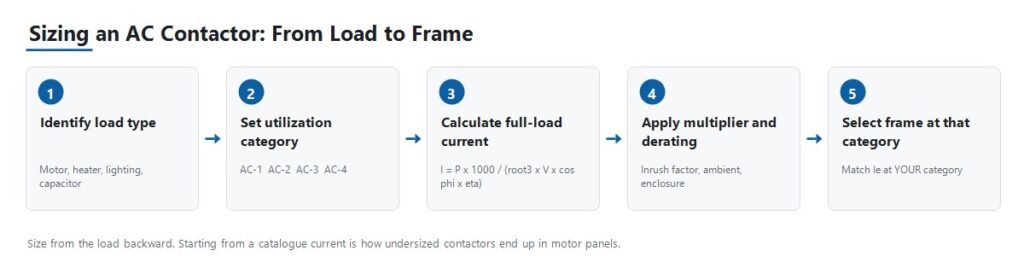
Step 1: Identify the Load Type and Utilization Category
Establish whether the load is resistive, a standard squirrel-cage motor, a wound-rotor motor starting under load, or a motor subject to jogging and reversing. Everything downstream depends on this answer, because it determines which of the contactor’s several current ratings actually applies.
Step 2: Calculate Operational Current and Confirm Voltage
Use the formulas above to obtain full-load current, apply the relevant load-type multiplier, then confirm that the contactor’s rated operational current Ie at your utilization category covers it with margin. Match the rated operational voltage Ue to the system line voltage.
Step 3: Select Coil Voltage
Coil voltage is a separate specification from load voltage. A 380 V motor circuit may be switched by a 24 V DC or 220 V AC coil depending on the control architecture. Confirm what the control circuit actually supplies, whether that is a PLC output, a control transformer secondary, or a DC control supply, before ordering.
Step 4: Choose Pole Count and Configuration
Three-pole is standard for three-phase motor loads. Four-pole is used where neutral switching or an additional independent circuit is required. Confirm the arrangement against the system earthing design, since neutral switching is required in some systems and unnecessary or prohibited in others.
Step 5: Specify Auxiliary Contacts
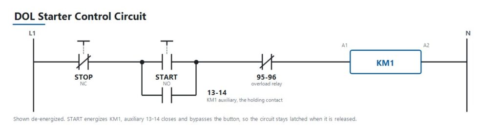
Determine how many normally open and normally closed auxiliary contacts are needed for interlocking, PLC status feedback, and indicator lamps, and whether they are integral or added as a separate auxiliary block. In a standard direct-on-line starter, an auxiliary contact wired in parallel with the start button is what latches the control circuit so the contactor stays energized after the operator releases the button. Auxiliary contacts are inexpensive to specify at design stage and awkward to retrofit afterwards.
Step 6: Check Electrical Life Against Actual Duty Cycle
For frequently cycling applications such as jogging, reversing, or high-frequency automation sequences, check the rated operations per hour and the electrical life at your utilization category. Mechanical life, measured without load, is always the higher and less relevant figure.
Step 7: Coordinate with Upstream Protection
Pair the contactor with a correctly sized overload relay for motor loads, then coordinate with an upstream breaker or fuse sized for short-circuit protection. On larger distribution boards that upstream device is often an air circuit breaker. Contactor selection is one link in a chain that runs from load current, to breaker rating, to prospective fault current, to device breaking duty. Getting the contactor right while leaving that chain unverified simply relocates the problem.
IEC 60947-4-1 and NEMA Ratings Are Not Interchangeable Labels
AC contactors sold internationally are generally built to IEC 60947-4-1, which defines the utilization categories and the rating structure used throughout this guide. The current fifth edition was published in 2023 and supersedes the 2018 edition. It is worth checking which edition a project specification references, because they are not identical.
North American markets commonly reference NEMA ICS 2 contactor ratings instead of, or alongside, IEC utilization categories. The two systems classify contactors differently, since NEMA uses size classes rather than AC-1 through AC-4. A specification written for one market does not translate automatically to the other. When sourcing for a North American project, confirm which framework the buyer’s specification actually requires before quoting a part.
Treat the product standard, the installation code, and any market-specific requirement as three separate questions. Confirming one does not answer the others.
Type 1 and Type 2 Coordination
Short-circuit coordination under IEC 60947-4-1 determines how much damage a fault causes to the contactor and starter. Type 1 permits damage to the equipment after a short-circuit fault, provided the damage is contained and no hazard results, and the equipment may require repair or replacement. Type 2 requires that the equipment remains suitable for further use, with only light contact welding permitted. These are different commercial and engineering outcomes. Confirm which one the project specification requires before selecting the combination.
Choosing Between the JUTRION JRC1 Ratings
JUTRION manufactures the JRC1 series AC contactor on its own production lines in Wenzhou, Zhejiang, built to IEC 60947-4-1. Coil voltage options include 24 V, 48 V, 110 V, 220 V, and 380 to 415 V at 50 or 60 Hz. Every unit is tested for mechanical operation, coil performance, and electrical switching before shipment.
The following are published rating points across the four utilization categories. Read the table by category rather than by model, since the same frame appears under more than one category with a different rating.
| Catégorie | Rating point | Duty this represents |
|---|---|---|
| AC-1 | JRC1-D09, 20 A | Résistances de chauffage, batteries de chauffage CVC, éclairage général |
| AC-2 | JRC1-D25, 25 A | Wound-rotor motors starting under load, cranes and hoists |
| AC-3 | JRC1-D09, 9 A | Squirrel-cage motors, normal start and stop, pumps and fans |
| AC-4 | JRC1-D18, 7.7 A | Jogging, plugging, rapid reversing, elevators and conveyors |
The JRC1-D09 appears twice, at 20 A under AC-1 and 9 A under AC-3, because those are two ratings of the same physical contactor under two different duties. For a standard induction-motor circuit, which covers the majority of pump, fan, and compressor applications, size against the AC-3 rating as shown in the worked example. For jogging or reversing duty, size against AC-4 instead, where the same frame carries substantially less current.
Frame ratings above these published points are available. Final model selection should be based on the model-specific ratings and project conditions, not on a current figure alone.
Apply the Selection Logic to Five Panel Scenarios
Standard Motor Panel for Pumps, Fans, and Compressors
An OEM building control panels for HVAC or water-treatment equipment specifies contactors for straightforward motor start and stop duty. This is category AC-3. Size the AC-3 rating against the calculated full-load current, pair it with a correctly sized overload relay, and match the coil voltage to the panel’s control transformer output.
Crane or Hoist Panel with Wound-Rotor Motors
A crane OEM requires contactors that handle high-torque starting and plugging duty on wound-rotor motors, which is category AC-2. These loads are harder on the contacts than standard AC-3 duty because of repeated starting under load and reversing. Undersizing here appears as premature contact wear rather than immediate failure, which makes it easy to misdiagnose as a quality problem.
Elevator or Conveyor Control with Jogging and Reversing
A machine builder needs contactors for an application with frequent direction reversal and inching moves, which is category AC-4, the most demanding of the four. Electrical life at the actual operations-per-hour rate matters more here than in any other scenario. Undersizing this category is the fastest way to consume a contactor’s rated life.
Capacitor Bank Switching for Power Factor Correction
A facility adding power-factor-correction capacitors needs contactors sized against capacitive inrush, conventionally about 1.5 times capacitor rated current, and frequently specified with pre-charging resistors or as dedicated capacitor-switching contactors. Standard AC-1 sizing is not adequate, because capacitive inrush is a distinct switching duty rather than a mild version of resistive duty.
Resistive Heating or Lighting Panel
A panel builder switching HVAC heating banks or large lighting loads is working in category AC-1, the least demanding, since there is no significant inrush or inductive kick to manage. Discharge and HID lighting are the exception and require the 1.1 to 1.4 multiplier for ballast inrush. This is also the case where buyers sometimes over-specify by choosing an AC-3-rated part where AC-1 would serve, which is not unsafe, only unnecessary cost.
Avoid the Nine Mistakes That Cause Early Contactor Failure
| Mistake | Consequence | Prevention |
|---|---|---|
| Sizing against the AC-1 rating for a motor load | Contactor undersized for its real duty, contacts weld or wear out early | Always size against the rating for the actual utilization category |
| Omitting the overload relay | Motor and contactor both exposed to sustained overcurrent | Pair every motor circuit with a correctly sized overload relay |
| Ignoring switching frequency against electrical life | A correctly current-sized contactor still fails early in high-cycle duty | Check rated operations per hour and electrical life at your category |
| Mismatched coil voltage | Contactor fails to pull in, or the coil burns out | Confirm against the actual control-circuit voltage, not the load voltage |
| No upstream coordination check | A short-circuit fault destroys the contactor unnecessarily | Verify Type 1 or Type 2 coordination before finalizing the design |
| Reversing contactors without interlocking | Both contactors can close together, creating a phase-to-phase short | Specify both mechanical and electrical interlocking on reversing pairs |
| Ignoring ambient temperature and enclosure derating | Shortened life despite every other specification being correct | Derate using the product curve and the enclosure temperature |
| Forgetting the load-type multiplier | Capacitor, transformer, or lighting inrush degrades contacts over time | Apply the conventional multiplier for the load type |
| Specifying auxiliary contacts too late | Costly panel rework or awkward add-on blocks | Determine interlocking and feedback needs at design stage |
Install, Commission, and Diagnose the Contactor
Most contactor faults reported as product defects are symptoms of a sizing, coordination, or control-supply problem. The table below maps the common symptoms to the checks that identify the cause.
| Symptom | Possible causes | Useful checks |
|---|---|---|
| Chatters or hums loudly | Low or unstable coil voltage, worn shading coil, dirty or loose magnetic core | Measure coil voltage under load, inspect the core face, verify control supply stability |
| Contacts welded shut | Undersized for the actual category, short-circuit event without adequate coordination, excessive switching frequency | Verify category sizing, review upstream fault history, compare operations per hour against rated electrical life |
| No pickup although the control signal is present | Open-circuit coil, wrong coil voltage, mechanical binding, blown control fuse | Measure coil resistance and voltage at the terminals, check the control fuse, inspect for obstruction |
| Contacts pitted or burned | Normal end-of-life wear, undersized for duty category, poor arc suppression at high switching frequency | Compare condition against rated electrical life, re-verify category sizing, inspect the arc chute |
| Auxiliary feedback disagrees with the main contact state | Worn or misaligned auxiliary block, mechanical linkage wear | Test auxiliary continuity independently, inspect the linkage to the main contact assembly |
| Terminals overheating | Loose termination, undersized conductor, incorrect torque at installation | Check terminal torque against specification, verify conductor sizing, thermal-image under load |
| Coil burns out repeatedly | Sustained overvoltage on the control circuit, excessive ambient temperature, mechanical binding preventing full pull-in | Measure control voltage under all operating conditions, check for binding, verify ambient temperature |
Repeated early failures in the same application almost always indicate a sizing, coordination, or duty-cycle mismatch rather than a defective batch. Diagnose the cause before re-ordering the same part number.
Protect the Coil and Whatever Drives It
De-energizing an inductive coil produces a voltage transient. When a PLC transistor output, a small interposing relay, or an electronic controller switches that coil directly, the transient travels back into it. This is a routine cause of PLC output failures and of pitted contacts on interposing relays, and it is straightforward to design out. Use an RC snubber across AC coils, and a flyback diode or varistor on DC coils. Note the trade-off: a plain flyback diode noticeably extends drop-out time, which matters when the contactor forms part of a safety-related stop function with a specified response time.
Confirm the coil’s operating voltage tolerance rather than assuming the nominal figure holds. A long control cable run or an undersized control transformer can put the actual coil voltage below the band in which the coil will pull in and hold, and the symptom appears as chattering rather than as an obvious wiring fault.
State These Parameters When Requesting a Quote
A contactor enquiry that includes the following information can be answered with a specific model in the first reply. An enquiry that gives only an ampere figure normally requires several rounds of clarification, because a bare current value does not identify the duty it applies to.
- Application or equipment being controlled
- Load type: motor, heater, lighting, capacitor, or transformer
- Utilization category, if already determined
- Motor rated power in kW, or load in kW
- System voltage and frequency
- Calculated full-load current
- Duty: starts per hour, and whether the application reverses or jogs
- Required coil voltage, and whether AC or DC
- Pole count, three-pole or four-pole
- Auxiliary contacts required, normally open and normally closed
- Upstream protective device, breaker or fuse
- Panel ambient temperature
- Mounting arrangement, DIN rail or screw
- Order quantity and destination market
- Any OEM or ODM requirements
Questions fréquemment posées
Quelle est la différence entre un contacteur CA et un démarreur de moteur ?
Un démarreur de moteur est un contacteur combiné à un relais de surcharge dans un seul ensemble, conditionné spécifiquement pour les circuits de moteur. Un contacteur autonome assure uniquement la fonction de commutation, et la protection contre les surcharges est ajoutée séparément.
Un contacteur peut-il être utilisé à la fois pour des charges AC-1 et AC-3 ?
The same physical contactor is usually rated for several categories, but at a different current rating for each. Size against the rating that matches the actual load’s utilization category, not the highest number on the label.
Comment calculer le courant pour le dimensionnement d'un contacteur ?
For a three-phase motor, use I = P × 1,000 / (√3 × VLL × cos φ × η), where P is rated power in kW, VLL is line-to-line voltage, cos φ is power factor, and η is efficiency. Then apply any load-type multiplier and confirm the result against the contactor’s rating at your utilization category.
Un contacteur plus grand est-il toujours plus sûr ?
No. Oversizing wastes cost and panel space, and on some loads an oversized contactor’s contacts carry too little current to stay clean. Size with sensible margin over the calculated full-load current at the correct category rather than jumping two frame sizes.
Quelle tension de bobine dois-je choisir ?
Faites-le correspondre à ce que le circuit de commande fournit réellement, qu'il s'agisse d'une sortie d'automate, du secondaire d'un transformateur de commande ou d'une alimentation de panneau en courant continu. Ce n'est pas la tension côté charge que le contacteur commute.
Pourquoi mon contacteur ronronne-t-il ou cliquette-t-il ?
Les causes habituelles sont une tension de bobine faible, instable ou incorrecte, ou une face de noyau magnétique usée ou sale sur une unité à bobine CA. Mesurez la tension de la bobine dans des conditions de charge réelles et inspectez la face du noyau avant de conclure que l’unité est défectueuse.
Ai-je encore besoin d’un relais de surcharge si j’utilise un contacteur ?
Yes, for motor circuits. A contactor switches on command but does not trip on sustained overcurrent, which is the overload relay’s function. The two devices work together and do not substitute for one another.
How many switching cycles can a contactor handle?
It depends on the frame size and, more importantly, on the utilization category and current level at which it operates. Mechanical life measured without load is typically far higher than electrical life under load, and electrical life falls further at higher switching frequencies. Check the rated electrical life at the actual duty cycle.
Can two contactors be wired in parallel to share current?
This is generally not recommended for main load switching. Contacts never close at exactly the same instant, so one device carries the full making current. Use a correctly sized single contactor instead.
What is the difference between Type 1 and Type 2 coordination?
Under IEC 60947-4-1, Type 1 permits damage to the contactor and starter after a short-circuit fault provided the damage is contained and no hazard results. Type 2 requires that the equipment remains suitable for further use, with only light contact welding permitted. Confirm which the project specification requires.
Do I need to derate the contactor for high ambient temperature?
Yes. The rated current assumes a datasheet reference ambient. Above that temperature, capacity falls. Use the manufacturer’s derating curve and base it on the temperature inside the enclosure rather than the room temperature.
How do I test an AC contactor with a multimeter?
With the circuit isolated and locked off, measure coil resistance across A1 and A2. An open circuit or a near-zero reading indicates a failed coil. Then check continuity across each main pole, which should read open when de-energized and closed when the contactor is pressed in manually. Compare all three poles, since one pole reading noticeably differently points to contact damage on that pole.
Size From the Load, Not From the Catalogue
A reliable contactor selection is derived from what the application demands and works forward to a part number. Starting from an available frame size and hoping the duty fits is how undersized contactors end up in motor panels.
The practical order is straightforward: define the load and its utilization category, calculate the full-load current, apply the load-type multiplier and ambient derating, then verify the contactor’s rated operational current at that category. Only after the ampere figure is settled do the pole, coil, auxiliary contact, electrical life, and short-circuit coordination checks complete the specification.
Once those inputs are confirmed, compare them against the available configurations in the JUTRION AC contactor range. Final model selection should follow the model-specific ratings and the project conditions, not the current figure alone.
