

Szybka odpowiedź: Jakiej wielkości skrzynki zbiorczej (combiner box) do instalacji fotowoltaicznej potrzebujesz?
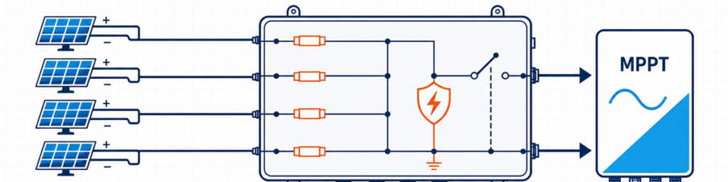
Cztery łańcuchy PV podłączone przez bezpiecznikową skrzynkę zbiorczą do wejścia MPPT falownikaSkrzynka łączeniowa instalacji fotowoltaicznej powinna odpowiadać liczbie kompatybilnych łańcuchów PV zasilających jedno wejście falownika, najwyższemu napięciu obwodu otwartego przy niskiej temperaturze, łącznemu prądowi projektowemu opartemu na Isc oraz wymaganej ochronie w danym miejscu. Sama liczba wejść nie wystarczy. Cztery łańcuchy mogą wymagać jednej skrzynki 4-we/1-wy, dwóch oddzielnych obwodów 2-we/1-wy lub w ogóle zewnętrznej skrzynki łączeniowej, w zależności od falownika i układu kabli.
Dla kupującego “4 łańcuchy, 1000 V” brzmi jak użyteczna specyfikacja. Dla inżyniera sprawdzającego ofertę to dopiero początek. Z karty katalogowej modułu może wynikać, że łańcuch zbliża się do 1000 V w zimny poranek. Falownik może przypisać łańcuchy do dwóch niezależnych MPPT. Ścieżka wyjściowa może musieć przenosić blisko 70 A po uwzględnieniu współczynnika prądowego projektu. Każdy z tych faktów może zmienić skrzynkę.
Celem jest przekształcenie informacji już obecnych w karcie katalogowej modułu, zestawieniu falowników i schemacie jednokreskowym w możliwą do obrony wstępną specyfikację. Ogólne konfiguracje i dostępne opcje produktów można znaleźć w gamie skrzynek zbiorczych JUTRION PV.
Zacznij od rysunku falownika, a nie od liczby łańcuchów na dachu
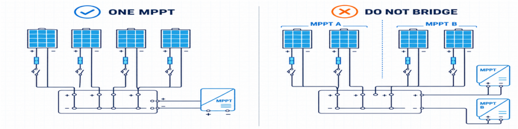
Prawidłowe grupowanie łańcuchów PV dla jednego MPPT w porównaniu z nieprawidłowym mostkowaniem oddzielnych wejść MPPTŁańcuchy wchodzące do jednego wyjścia skrzynki zbiorczej muszą mieć dokąd poprawnie trafić. Brzmi to oczywiście, ale właśnie tutaj wiele wczesnych wycen idzie źle.
Załóżmy, że na dachu jest osiem łańcuchów. Rysunek falownika przypisuje cztery do MPPT A i cztery do MPPT B. Zastosowanie skrzynki zbiorczej 8-we/1-wyj połączyłoby dwa obwody, które falownik został zaprojektowany do niezależnego sterowania. Realne wybory to zwykle dwie oddzielne grupy 4-we/1-wyj, jedna obudowa zawierająca dwie elektrycznie niezależne sekcje lub bezpośrednie połączenia łańcuchów, jeśli falownik zapewnia już odpowiednie wejścia i zabezpieczenia.
Łańcuchy przeznaczone do pracy równoległej powinny być również rzeczywiście kompatybilne. Sprawdź typ modułu, liczbę modułów na łańcuch, orientację i przewidywane zacienienie. Nierówne długości łańcuchów mają różne napięcia robocze. Łączenie silnie zacienionych i niezacienionych łańcuchów może również dawać słabe dopasowanie robocze, nawet gdy etykiety modułów są identyczne.
To daje pierwszą użyteczną zasadę:
Policz łańcuchy przypisane do jednej kompatybilnej ścieżki MPPT, a nie każdy łańcuch widoczny na rysunku projektu.
Kiedy zewnętrzna skrzynka zbiorcza wnosi niewiele wartości
Wiele falowników łańcuchowych zapewnia już wiele wejść DC, wewnętrzną ochronę przeciwprzepięciową i funkcję odłączania DC. Jeśli każdy łańcuch może być poprowadzony bezpośrednio do odpowiedniego wejścia falownika, dodanie zewnętrznej skrzynki zbiorczej może stworzyć dodatkowe zakończenia kabli bez rozwiązywania problemu projektowego.
Skrzynka jednołańcuchowa to powiązany, ale inny przypadek. Jednostka 1-we/1-wyj nie łączy prądów; działa jako zewnętrzna skrzynka zabezpieczeniowa i odłączająca. Może to być przydatne, gdy falownik jest oddalony, wymagany jest lokalny punkt odłączenia lub projekt chce mieć wymienną ochronę przeciwprzepięciową w dostępnym miejscu.
Pięć liczb, które warto umieścić na jednej kartce
Zanim zaczniesz sprawdzać rozmiary bezpieczników lub wymiary obudowy, zbierz pięć grup informacji. Większość można skopiować bezpośrednio z wydanych dokumentów projektu.
| Informacja | Skąd zwykle pochodzi | Co zmienia |
|---|---|---|
| Voc, Isc, Imp, współczynnik temperaturowy i maksymalny bezpiecznik szeregowy | Karta katalogowa modułu PV | Limity napięcia, prądu i bezpiecznika łańcucha |
| Moduły na string i liczba równoległych stringów | Harmonogram stringów | Liczba wejść i całkowite napięcie/prąd |
| Układ MPPT i limity wejściowe | Karta katalogowa falownika i schemat jednokreskowy | Które stringi mogą współdzielić wyjście |
| Temperatura minimalna, montaż i ekspozycja | Podstawa projektowa i dane lokalizacyjne | Zimne Voc, obniżanie wartości znamionowych i obudowa |
| Kraj docelowy i obowiązujące przepisy | Specyfikacja projektu | Metoda ochrony i dokumentacja |
Jedną z wartości, która często umyka, jest maksymalny dopuszczalny prąd zwarciowy falownika. Maksymalny prąd roboczy i maksymalny prąd zwarciowy nie są wymienne. Proponowany układ należy sprawdzić pod kątem obu.
Kraj docelowy ma znaczenie tak samo jak dane elektryczne. Obliczenie bezpiecznika przygotowane dla projektu zorientowanego na IEC nie powinno po cichu zapożyczać mnożnika północnoamerykańskiego i przedstawiać go jako uniwersalnej zasady.
Sprawdź napięcie zimnego stringu przed wyborem 1000 V lub 1500 V
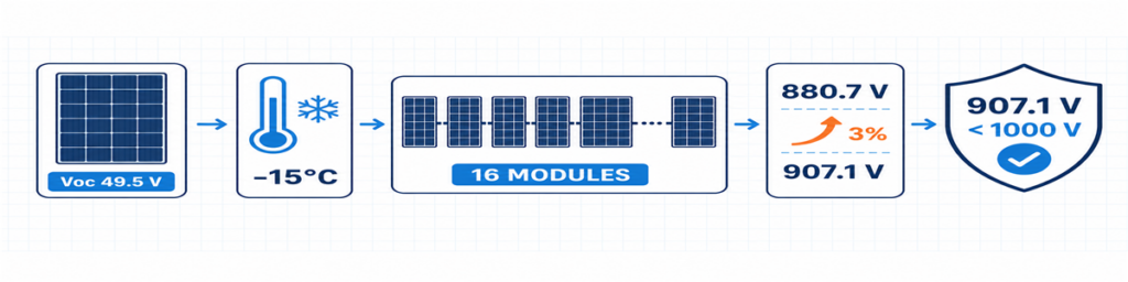
Obliczenie Voc stringu PV w niskich temperaturach dla 16 modułów dające napięcie projektowe 907,1 VVoc modułu jest zwykle podawane w standardowych warunkach testowych. Rośnie ono, gdy temperatura ogniwa spada, więc najzimniejszy przewidywany warunek decyduje o maksymalnym napięciu stringu.
Gdy karta katalogowa modułu podaje ujemny współczynnik temperaturowy Voc jako procent na stopień Celsjusza, wstępne obliczenie wygląda następująco:
Voc,zimne = Voc,STC × [1 + |βVoc| × (25 − Tmin)]
Vstring,zimne = Voc,zimne × liczba modułów w szeregu
Wprowadź współczynnik jako ułamek dziesiętny. Na przykład −0,28%/°C staje się 0,0028 we wzorze. Jeśli producent modułu podaje inną metodę dla niskich temperatur, należy zastosować tę metodę.
Odpowiedź musi pasować nie tylko do falownika. Wkładka topikowa i oprawka, SPD, rozłącznik z bezpiecznikami lub wyłącznik, zaciski, przewody i gotowy zespół znajdują się w tym samym obwodzie DC. Wymiana samego SPD na urządzenie 1500 V nie przekształca skrzynki 1000 V w zespół 1500 V.
Niewielki niewykorzystany zapas napięcia to nie zmarnowana pojemność. Absorbuje on projektową bazę temperaturową i tolerancje, które faktycznie zidentyfikowano. Należy unikać przypadkowego zapasu bez udokumentowanego źródła.
Bezpieczniki łańcuchowe zależą od prądu wstecznego, a nie od przyzwyczajenia
Gdy równoległe łańcuchy są zdrowe, każdy z nich dostarcza prąd do wspólnego wyjścia. Jeśli w jednym łańcuchu wystąpi awaria, pozostałe mogą podawać do niego prąd wsteczny. Bezpiecznik łańcuchowy służy do przerwania tego szkodliwego prądu wstecznego tam, gdzie wymagana jest ochrona.
Wstępne oszacowanie udziału pozostałych łańcuchów to:
Iprąd,wsteczny = (n − 1) × Isc,łańcuch
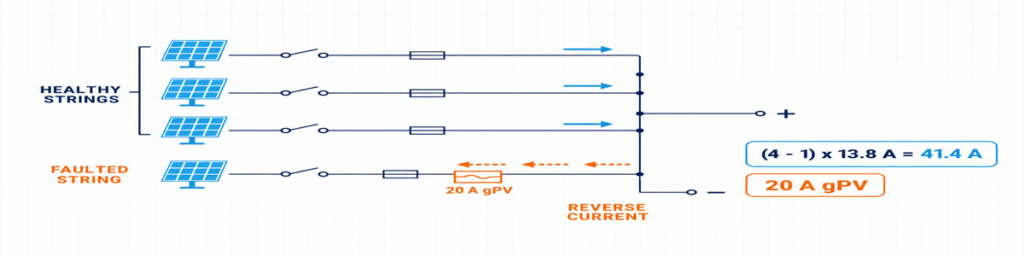
Prąd wsteczny z trzech zdrowych łańcuchów PV do uszkodzonego łańcucha chronionego bezpiecznikiem gPV 20 ATutaj n to liczba równoległych łańcuchów. Wyrażenie pokazuje, dlaczego odpowiedź zmienia się szybko między dwoma a czterema wejściami: uszkodzony łańcuch w grupie czterech łańcuchów może otrzymywać prąd z trzech zdrowych łańcuchów.
Nie należy traktować tego wyrażenia jako gotowego projektu ochrony. Wybrany bezpiecznik gPV musi przenosić oczekiwany prąd w rzeczywistych warunkach obudowy, chronić kabel i urządzenia, mieścić się w maksymalnym prądzie bezpiecznika szeregowego modułu oraz mieć odpowiednie napięcie DC PV i zdolność wyłączania. Oprawka i bezpiecznik są sprawdzane razem, z uwzględnieniem efektów temperatury i grupowania.
IEC 60269-6 obejmuje dodatkowe wymagania dla wkładek topikowych stosowanych w łańcuchach i układach fotowoltaicznych do 1500 V DC. Zasady instalacji przyjęte dla projektu określają sposób zastosowania tego produktu.
O wartości 1,56 × Isc spotykanej w internecie
Znana wartość 1,56 × Isc jest związana z dwoma współczynnikami 125% stosowanymi w powszechnych północnoamerykańskich ścieżkach projektowych. Nie należy jej przeetykietowywać jako uniwersalnego wzoru IEC. Jeśli projekt podlega przepisom NEC, należy stosować przyjętą edycję, wykazy sprzętu i wymagania lokalne. Jeśli jest to projekt IEC, należy stosować odpowiednie zasady instalacji oparte na IEC oraz instrukcje producentów modułów, bezpieczników i kabli.
To rozróżnienie warto zaznaczyć w wycenie. W przeciwnym razie dwóch dostawców może podać różne rozmiary bezpieczników, mimo że obaj otrzymali te same dane dotyczące instalacji.
Zwymiaruj ścieżkę wspólną oddzielnie od każdego wejścia
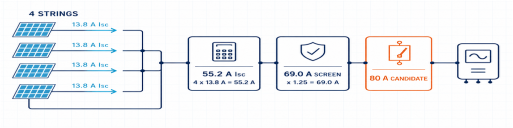
Cztery łańcuchy PV 13,8 A połączone do 55,2 A Isc z ekranem projektowym 69 A i kandydatem na urządzenie wyjściowe 80 AStrona wejściowa i wyjściowa przewodzą różne prądy. Każde wejście przenosi jeden łańcuch; wspólne wyjście przenosi sumę równoległych łańcuchów.
Isc,ogółem = liczba równoległych łańcuchów × Isc,łańcuch
Wymagany współczynnik projektowy projektu i współczynniki korekcyjne są następnie stosowane do odpowiednich przewodów i urządzeń. Wynik wpływa na okablowanie wewnętrzne, szyny zbiorcze, zaciski, kabel wychodzący i urządzenie przełączające wyjście. Należy go również porównać z limitami podanymi przez falownik.
Używanie samego Imp do całego doboru może sprawić, że ścieżka zabezpieczeniowa będzie zbyt mała. Używanie samego Isc bez sprawdzenia normalnego prądu MPPT falownika może przeoczyć ograniczenie robocze. Trzymaj wartości oddzielnie i nadaj każdej z nich cel.
| Wartość | Użyj jej do sprawdzenia |
|---|---|
| Imp łańcucha | Normalny prąd roboczy i kompatybilność z MPPT falownika |
| Isc łańcucha | Prąd projektowy łańcucha i obliczenia zabezpieczeń nadprądowych |
| Całkowity Isc | Ścieżka wspólna i limit prądu zwarciowego falownika |
| Skorygowany prąd projektowy projektu | Przewody, szyny zbiorcze, zaciski i urządzenie wyjściowe w warunkach zainstalowania |
Ciepło może unieważnić pozornie wygodną wartość katalogową. Ciasno zgrupowane oprawki bezpiecznikowe, straty na zaciskach, SPD i bezpośrednie promieniowanie słoneczne zwiększają temperaturę wewnątrz obudowy. Urządzenie 80 A w warunkach odniesienia nie jest automatycznie rozwiązaniem 80 A w każdej obudowie zewnętrznej.
Bezpieczniki, odłączniki, wyłączniki i SPD mają różne zadania
Skrzynkę łączeniową łatwiej jest wyspecyfikować, gdy każdy element ma jedno jasne zadanie:
- bezpiecznik gPV: chroni pojedynczy łańcuch przed odpowiednim stanem prądu wstecznego;
- rozłącznik izolacyjny: zapewnia łączenie obciążenia o parametrach DC dla PV i zdefiniowany punkt izolacji;
- wyłącznik DC: przełącza obwód i zapewnia funkcję nadprądową, gdy jego charakterystyki i zdolności wyłączania DC odpowiadają zastosowaniu;
- SPD DC PV: limits transient overvoltage and does not replace overcurrent protection or isolation.
An output breaker is not mandatory simply because there is room for one. The system design may call for a switch-disconnector where overcurrent protection is already provided elsewhere, or for a breaker with a defined protective duty. Decide the function first.
The same principle applies to the SPD. Confirm the PV DC application, UCPV, protection modes, protection level, discharge-current duty, short-circuit behaviour and backup coordination. Type 2 is commonly used for induced surge conditions. Where an external lightning protection system or another lightning-current path is present, the arrangement may need Type 1 or Type 1+2 protection. See the JUTRION PV DC SPD range after the project voltage and lightning context are known.
For the isolating function, a device rated for the intended PV duty is more meaningful than a generic “DC switch” description. The JUTRION PV DC isolator range includes DC-PV2 options for review against the required voltage, current and pole arrangement.
A Four-String Example from Datasheet to Box
Illustrative example: This is a constructed commercial-rooftop case used to show the calculation. It is not a customer project or a universal design.
Four identical strings are assigned to one high-current inverter input. Each string contains 16 modules. The module datasheet gives Voc = 49.5 V, Isc = 13.8 A, βVoc = −0.28%/°C and a maximum series-fuse rating of 25 A. The project minimum temperature is −15°C. Its design basis also applies a stated 3% allowance after the temperature calculation.
The illustrative inverter has a 1000 V maximum DC input, an 80 A maximum input current and a 100 A maximum short-circuit current. No external lightning protection system is assumed.
The Drawing Points to Four Inputs and One Output
All four strings use the same modules and string length, and the inverter documentation permits them to feed the same input. A 4-in/1-out architecture is therefore appropriate at this stage. If the drawing divided them between two MPPTs, the answer would become two independent 2-in/1-out groups.
The Cold String Reaches 907.1 V
Cold module Voc = 49.5 × [1 + 0.0028 × (25 − (−15))] = 55.04 V
Cold string Voc = 55.04 × 16 = 880.7 V
Project design voltage = 880.7 × 1.03 = 907.1 V
A verified 1000 V assembly can pass this preliminary check, as can the illustrative inverter. The remaining margin is about 93 V. A seventeenth module would raise the result to approximately 964 V before the same allowance and would not pass this example after the allowance is applied.
Parallel Strings Make Individual Fusing Necessary
The other three strings can contribute an initial reverse-current screen of:
(4 − 1) × 13.8 = 41.4 A
That is above the module’s 25 A maximum series-fuse rating, so individual string protection is required in this example. The project method produces a preliminary lower fuse-current screen of 1.25 × 13.8 = 17.25 A. A 20 A gPV fuse sits between that value and the 25 A module limit. Before it is accepted, its holder, cable protection, enclosure temperature and continuous-current capability must be checked.
The Common Output Needs More Than a 55.2 A Label
The combined short-circuit current is:
4 × 13.8 = 55.2 A
The example design basis uses 1.25 × Isc as its preliminary output-current screen:
1.25 × 55.2 = 69.0 A
An 80 A PV DC switch-disconnector is a reasonable starting frame, not an automatic final choice. The installed thermal rating, voltage, poles and switching duty remain to be checked. The inverter’s 100 A short-circuit limit passes the 55.2 A comparison. Its 80 A operating limit should be compared with four times the module Imp from the real datasheet.
The preliminary box is now specific enough to review: four independently fused inputs, one combined output, 1000 V-class components throughout, a combined path designed around the stated 69 A screen, PV DC isolation and a Type 2 PV DC SPD subject to final coordination.
The Result on One Page
The calculation is easier to review when the assumptions, result and remaining check are kept together. This is also the point where a buyer can see whether two quotations are actually based on the same duty.
| Selection item | Illustrative result | What still needs confirmation |
|---|---|---|
| Configuration | 4 inputs / 1 output | All four strings feed one compatible inverter input |
| Maximum project voltage | 907.1 V | Site temperature basis, tolerance method and inverter limit |
| String protection | 20 A gPV preliminary selection | Fuse-holder temperature, cable protection and applicable rules |
| Combined short-circuit current | 55.2 A | Inverter maximum permissible short-circuit current |
| Preliminary output-current screen | 69.0 A | Correction factors and installed assembly temperature |
| Output isolation | 80 A frame is a starting candidate | PV DC duty, voltage, poles and installed current rating |
| Surge protection | Type 2 PV DC SPD initially | Ucpv, protection modes, LPS and backup coordination |
| Obudowa | Outdoor IP65 minimum | UV, corrosion, heat, glands and condensation |
Choosing Between a 1/1, 2/1 and 4/1 Configuration
JUTRION currently displays 1000 V DC, IP65 products in 1-in/1-out, 2-in/1-out and 4-in/1-out configurations. Use the input count to shortlist the architecture, then confirm the ratings that the project calculation produced.
| Configuration | Typical reason to shortlist it | Reason to stop and reconsider |
|---|---|---|
| 1 input / 1 output | One string needs an accessible protection and isolation point | No combining occurs; verify that a separate box adds a required function |
| 2 inputs / 1 output | Two matched strings feed one inverter input | The strings belong to separate MPPTs or exceed the combined-input limits |
| 4 inputs / 1 output | Four matched strings feed one suitably rated high-current input | The inverter needs two MPPT groups or the output path is underrated |
The worked example points toward a JUPV1000-4/1 architecture. It does not approve the internal fuse, output device or SPD by model name alone. Those parts have to be quoted against the 907.1 V project voltage, the proposed 20 A gPV string protection, the 69 A preliminary combined-current screen and the outdoor installation conditions.
Custom 1500 V or larger-string configurations deserve a fresh component and assembly check. They should not be treated as a label change to the 1000 V stock arrangement.
The Outdoor Enclosure Can Change the Current Rating
Electrical calculations are often completed in an office at 25°C. The box may spend its working life on a roof where the air is much hotter, direct sunlight warms the enclosure, and several fuse-holders carry current side by side. That difference affects more than comfort during maintenance.
Heat is produced at fuses, terminals, conductors, the SPD and the output device. Closely packed components have less opportunity to cool, while a sealed enclosure restricts air exchange. A component that carries its marked current under its reference conditions may require derating in the final assembly. This is why the 80 A switch-disconnector in the example remains a starting frame until the installed arrangement has been checked.
IP65 is useful, but it answers only an ingress-protection question. It does not automatically establish:
- resistance to long-term ultraviolet exposure;
- corrosion performance near the coast or in an industrial atmosphere;
- acceptable internal temperature under full current and solar loading;
- condensation control during daily heating and cooling;
- suitability of cable glands, seals and materials for the installed cables;
- insulation performance at high altitude.
Mounting details also matter. Cable entries made through the top of an outdoor enclosure create a different water path from bottom entry. Undersized glands may damage seals or leave insufficient cable support. Tight cable bends can transfer mechanical force to fuse-holders and terminals. The enclosure should be reviewed as an installed assembly, not as an empty plastic or metal box with an IP number.
IEC 61439-2:2020 covers power switchgear and controlgear assemblies up to 1500 V DC. The relevance here is practical: using individually rated components does not remove the need to verify the completed assembly, including temperature rise, dielectric properties, protective circuits, clearances, wiring and mechanical construction as applicable.
Send Enough Information for the Supplier to Check the Result
A short technical enquiry is more useful than a long purchasing template. Attach the module and inverter datasheets and state:
- strings per output and modules per string;
- module Voc, Isc, Imp, βVoc and maximum series fuse;
- minimum design temperature and any voltage allowance;
- inverter MPPT arrangement and input limits;
- calculated maximum voltage and combined design current;
- required fuse, isolation, breaker and SPD functions;
- enclosure location, IP requirement, ambient, UV and corrosion exposure;
- cable sizes, monitoring, destination market and quantity.
For the illustrative project, that becomes: 4-in/1-out, four identical 16-module strings feeding one MPPT, 907.1 V stated project design voltage, preliminary 20 A gPV fuses, 55.2 A total Isc, 69 A preliminary output-current screen, PV DC isolation, coordinated Type 2 PV DC surge protection and an outdoor enclosure.
Why Two “4-String, 1000 V, IP65” Quotations May Not Be Equivalent
One quotation may use gPV fuse-links and holders verified for the intended voltage and temperature. Another may list only a nominal fuse current. One box may provide a load-break switch-disconnector; another may use a device intended mainly for isolation. SPD Ucpv, protection modes, short-circuit behaviour and replaceability may also differ even when both quotations say “Type 2 SPD.”
The common output is another source of hidden difference. Compare the installed current capability of the busbars, conductors, terminals and output device, not only the largest ampere number printed in the bill of materials. Also check terminal capacity against the actual outgoing cable. A technically lower-priced quotation is not cheaper if it requires replacement glands, a larger enclosure or rework at site.
A useful comparison therefore normalizes the following items before price:
- input/output arrangement and MPPT grouping;
- maximum DC voltage of the complete path;
- string-fuse class, rating and module limit;
- combined current and installed temperature conditions;
- output device function and DC duty;
- SPD type, Ucpv, modes and coordination;
- terminal and cable-gland capacity;
- enclosure material and environmental suitability.
The final selection should read as one connected electrical path. If the quotation confirms only input count, nominal voltage and IP rating, it has not yet answered the sizing question.
Verify the Box After Installation
A correct design can still be compromised by reversed polarity, loose terminations, damaged glands or a string connected to the wrong input. Commissioning should follow the project procedure and component instructions, with the DC circuit isolated and tested by qualified personnel.
Before energizing the combined output, record:
- string identity, polarity and measured open-circuit voltage;
- whether measured string voltages are reasonably consistent with the design and with one another;
- terminal tightening completed to the specified torque;
- protective-conductor and bonding continuity where required;
- fuse type and rating in every populated way;
- SPD status indication and remote alarm contact, if fitted;
- operation and position indication of the isolating device;
- labels, unused-entry seals, gland compression and enclosure closure.
After the system has operated under representative load, inspect for abnormal heating, discoloration, odour, nuisance fuse operation or moisture. Where the project maintenance plan uses thermography, the baseline image is more useful when load and ambient conditions are recorded with it. The purpose is not to “prove” the design from one scan, but to leave a reference for later comparison.
IEC 62548-1:2023 provides the broader IEC design context for PV arrays, including DC wiring, protection, switching and earthing. The completed assembly also needs appropriate verification; IEC 61439-2:2020 covers power switchgear and controlgear assemblies up to 1500 V DC. PV DC SPD requirements are addressed by IEC 61643-31.
To compare the result with a JUTRION configuration, send the string schedule, module and inverter data, site temperature, protection requirements and destination standard through the PV combiner box page. That gives both sides something more reliable to discuss than “four strings, best price.”
Często zadawane pytania
Ile łańcuchów solarnych wymaga skrzynki zbiorczej?
Nie ma uniwersalnego minimum. Zewnętrzny łącznik jest przydatny, gdy kompatybilne ciągi muszą być połączone równolegle przed jednym wejściem falownika, gdy skraca to długie przebiegi kablowe lub gdy projekt potrzebuje scentralizowanego miejsca na bezpieczniki, izolację, ochronę przeciwprzepięciową lub monitorowanie. Jeśli falownik już przyjmuje każdy ciąg bezpośrednio i zapewnia wymagane funkcje, oddzielny łącznik może nie być konieczny.
Jaki rozmiar bezpiecznika powinien być zastosowany w skrzynce połączeniowej solarnej?
Wybierz bezpiecznik gPV przystosowany do instalacji fotowoltaicznych na podstawie prądu zwarciowego Isc łańcucha, odpowiedniej metody instalacji, obciążalności kabla, warunków środowiskowych oraz maksymalnego prądu znamionowego bezpiecznika szeregowego modułu. Bezpiecznik musi przewodzić oczekiwany prąd bez zbędnych zadziałań, pozostając jednocześnie na tyle niskim, aby chronić moduł i kabel. Nie należy stosować 1,56 × Isc jako uniwersalnej zasady IEC; obliczenia zależą od normy docelowej.
Czy stringi podłączone do różnych MPPT mogą współdzielić jedną skrzynkę łączeniową?
Mogą one współdzielić fizyczną obudowę tylko wtedy, gdy obwody MPPT pozostają elektrycznie odseparowane. Nie należy łączyć wyjść niezależnych grup MPPT, chyba że producent falownika wyraźnie dopuszcza taką architekturę. Każda grupa powinna mieć własne kompatybilne łańcuchy, ścieżkę wyjściową i parametry znamionowe.
Czy potrzebuję skrzynki łączeniowej PV 1000 V czy 1500 V?
Calculate the maximum cold-weather open-circuit voltage of the complete string and include the allowances required by the project method. Select a voltage class that keeps the inverter and every component in the combiner path within rating. A 1500 V SPD alone does not make the completed box suitable for 1500 V.
What Is the Difference Between a PV Combiner Box and a PV Protection Box?
A PV combiner box joins two or more compatible string inputs into a common output. A 1-in/1-out PV protection box does not combine strings; it provides a convenient location for functions such as isolation, surge protection or overcurrent protection on one string circuit.
