

MCCB Механизм моторизованного управления: Руководство по управлению, выбору и модернизации
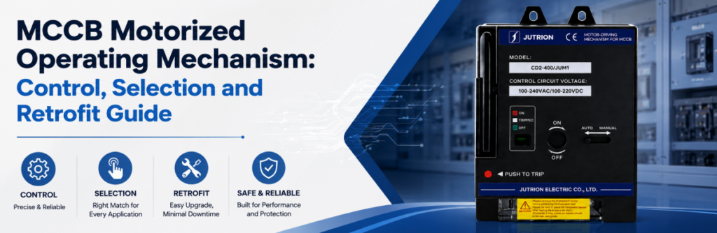
Руководство по управлению, выбору и модернизации моторного привода MCCBКраткий ответ: что делает моторный привод MCCB?
Моторный привод MCCB, также называемый моторным оператором MCCB, — это электрический исполнительный механизм, который по команде переводит совместимый автоматический выключатель в литом корпусе между его механическими состояниями. В зависимости от выключателя и подобранного механизма он может включать, отключать и возвращать выключатель в исходное состояние после срабатывания. Это единственный аксессуар выключателя, который может включать выключатель дистанционно — независимый расцепитель и расцепитель минимального напряжения могут только отключать его.
Диспетчерская отправляет команду ВКЛ на фидерный выключатель, и ничего не происходит. Обычное первое предположение — отказ двигателя. Двигатель часто исправен: выключатель может всё ещё находиться в состоянии СРАБОТАЛ, переключатель может быть в положении РУЧНОЙ, может отсутствовать разрешение на включение, или напряжение питания управления может просесть во время операции.
В этом главная мысль данного руководства. Моторный привод — это не электрическая рука, поворачивающая рукоятку. Это одно звено в цепи: система автоматизации выдаёт команду, разрешающая логика решает, допустима ли она, механизм перемещает выключатель, а вспомогательные контакты подтверждают результат. Если какое-либо звено не определено, “дистанционное управление MCCB” не является полноценной функцией.
Моторный привод также не является защитным устройством. Он не измеряет ток, не срабатывает при аварии и не повышает Iув выключателя и не изменяет его расцепитель. Он также не заменяет контактор: выключатель с моторным приводом предназначен для редких операций, а не для тысяч ежедневных циклов, которые требуются в моторной цепи.
Используйте это руководство в три прохода:
- Подтвердите, требуется ли проекту только дистанционное отключение или также дистанционный возврат и включение.
- Проверьте механическую совместимость, напряжение управления, потребность при пуске и падение напряжения в кабеле.
- Определите разрешающие условия, обратную связь, блокировки и поведение после защитного срабатывания.
Спецификация вкратце
| Решение | Что его определяет | Где покупатели ошибаются |
|---|---|---|
| Тип аксессуара | Требуется ли дистанционное включение , а не только отключение | Заказ независимого расцепителя для “дистанционного управления” |
| Требуемые движения | Только отключение или отключение–возврат–включение после срабатывания | Предположение, что “дистанционное включение” включает возврат из состояния СРАБОТАЛ |
| Механическая совместимость | Серия выключателя, типоразмер, полюса и монтаж — с заводской таблички | Подбор только по номинальному току |
| Напряжение управления | Падение напряжения на фактической длине кабеля | Выбор 24 В DC по привычке для длинного кабельного пролёта |
| Размер источника питания управления | Суммарная пусковая (бросковая) мощность в ВА плюс запас источника питания проекта | Расчёт по удерживающей нагрузке |
| Обратная связь | Контакт положения плюс отдельный контакт срабатывания/аварии | Один вспомогательный контакт для всего |
| Режим работы | Количество операций в год относительно номинальной износостойкости | Использование выключателя там, где нужен контактор |
Дистанционное управление начинается с трёх состояний выключателя, а не с двух
Ручной выключатель находится в положении ВКЛ или ОТКЛ. У MCCB есть третье состояние, которое определяет всю конструкцию дистанционного управления: СРАБОТАЛ. Команда включения не может рассматривать сработавший выключатель так, будто он просто отключён.
ВКЛ означает, что главные контакты замкнуты. Моторный привод не должен получать повторные команды включения, когда выключатель уже включён, поэтому обратная связь по положению надёжнее, чем предположение, что последняя команда выполнена успешно.
ОТКЛ означает, что контакты разомкнуты и механизм готов к нормальной операции включения, если разрешающие условия выполнены. Индикация ОТКЛ не доказывает, что цепь безопасна для работы; изоляция, блокировка и проверка отсутствия напряжения остаются отдельными требованиями.
СПОТКНУЛСЯ означает, что механизм сработал от защитного расцепления или команды отключения. Прежде чем выключатель сможет замкнуться снова, механизм обычно должен пройти через движение возврата. Аварийное отключение — это информация, а не просто другое положение рукоятки.
| Наблюдаемое состояние | Значение для системы управления | Разрешённое следующее действие | Требуемая обратная связь |
|---|---|---|---|
| ВКЛ | Главные контакты замкнуты | Удерживать или выдать команду ОТКЛ при необходимости | Контакт положения |
| ОТКЛ | Контакты разомкнуты, механизм готов к включению | ВКЛ только при выполнении разрешающих условий | Индикация разомкнутого положения и статус разрешения включения |
| СПОТКНУЛСЯ | Сработало защитное или дистанционное отключение | Провести проверку, выполнить возврат при наличии разрешения, затем повторно оценить включение | Индикация отключения/аварии, отличная от обычного ВЫКЛ |
| Движение или неподтверждённое состояние | Механизм работает, застопорился или обратная связь противоречива | Блокировать дальнейшие команды до истечения тайм-аута и диагностики | Таймер команды плюс сравнение положений |
Движение возврата — это отдельное механическое требование
После защитного отключения многим выключателям требуется, чтобы рукоятка прошла за нормальное положение ВЫКЛ, прежде чем механизм вернётся в исходное состояние. Моторный привод, предназначенный только для переключения ВКЛ/ВЫКЛ, может не обеспечить такой ход. Указывайте “дистанционный возврат после отключения” явно, а не предполагайте, что он входит в “дистанционное включение”.
Возврат также меняет логику обратной связи. Аварийный контакт может разомкнуться при возврате механизма, тогда как вспомогательный контакт ВЫКЛ может уже показывать разомкнутое состояние главных контактов. Если контроллер использует только сигнал ВЫКЛ как подтверждение, он может выдать команду ВКЛ, пока выключатель всё ещё механически отключён.
Моторный привод, независимый расцепитель или расцепитель минимального напряжения: подберите аксессуар под задачу
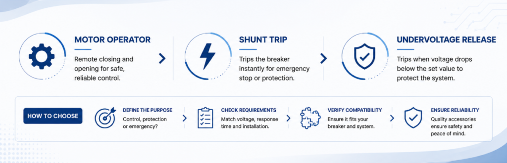
Моторный привод против шунтового расцепителя против расцепителя по пониженному напряжению для выбора аксессуаров MCCBДистанционное управление часто избыточно специфицируется, потому что эти аксессуары считаются взаимозаменяемыми. Они дополняют друг друга, и самое дорогое недоразумение в этой категории — купить независимый расцепитель и обнаружить, что он не может снова замкнуть выключатель.
| Возможность | Моторный привод | Независимый расцепитель (MX) | Расцепитель минимального напряжения (MN) | Вспомогательный контакт (OF) |
|---|---|---|---|---|
| Замыкает выключатель дистанционно | Да, если позволяет соответствующая конструкция | Нет | Нет | Нет |
| Размыкает выключатель дистанционно | Да | Да | Да, при исчезновении питания | Нет |
| Возвращается после отключения | Зависит от модели — уточняйте | Нет | Нет | Нет |
| Сообщает положение выключателя | Сам по себе нет | Нет | Нет | Да |
| Требует постоянного питания | Нет — потребляет только во время работы | Нет — под напряжением только для отключения | Да — удерживается под напряжением | Нет — без напряжения |
| При потере питания цепи управления | Выключатель сохраняет состояние; дистанционное управление отсутствует | Не может отключить | Отключает — по своей природе безопасно при отказе | Состояние контакта не меняется |
| Типичная роль | Привод дистанционного отключения, возврата и включения | Цепь пожарной сигнализации или аварийного отключения | Отказоустойчивое отключение и разрешение на включение | Подтверждение команды и блокировки |
Прочитайте последние две строки вместе. Расцепителю с шунтом требуется исправный источник управления для выполнения своей задачи; расцепитель минимального напряжения выполняет свою задачу именно тогда, когда питание теряется. Выбирайте между ними, задавая вопрос: что должно произойти, если сам источник управления выйдет из строя. Моторный привод отвечает на другой вопрос: кто включает выключатель, когда перед ним никто не стоит.
Моторный привод может механически отключить выключатель, и проект может по-прежнему требовать расцепитель с шунтом, поскольку цепи защиты или аварийные цепи часто нуждаются в независимом, четко определенном пути отключения. Они устанавливаются вместе, а не выбираются между собой.
Как моторный привод фактически перемещает выключатель
Команда поступает на механизм, работает зубчатый двигатель, и выключатель меняет состояние. Что происходит между этими точками, зависит от конструкции, и разница влияет на длительность команды, синхронизацию и то, что контроллер должен ожидать после потери питания.
Прямой привод. Двигатель перемещает рабочий интерфейс через полный ход, пока он запитан. Команда должна длиться достаточно долго для полного хода, и движение привода в целом повторяет рукоятку выключателя, что делает операцию легко наблюдаемой при пусконаладке.
Накопленная энергия. Двигатель взводит пружину, и пружина затем освобождается для перемещения контактов одним быстрым действием. Это развязывает скорость контактов от скорости двигателя, что позволяет контактам замыкаться достаточно быстро для ограничения преддугового разряда. Последовательность взвода и операция с контактами — это два отдельных события, и контроллер должен учитывать оба.
Ни один из подходов не является универсально лучшим. Решающий вопрос заключается в том, выполняет ли полная сборка выключателя и механизма требуемую последовательность отключения, сброса и включения при доступном источнике управления и в рамках временных параметров проекта. В обоих случаях двигатель останавливается после завершения операции, поэтому моторный привод создает большой кратковременный спрос и практически нулевую постоянную нагрузку.
Ручное управление должно оставаться четко определенным в любом случае. Текущая страница портфолио JUTRION указывает встроенный переключатель Авто/Ручной для диапазона моторных приводов. Подтвердите механическое зацепление заказанной модели, блокирует ли РУЧНОЙ удаленные команды, отключает ли он питание двигателя и получает ли контроллер обратную связь о положении переключателя. Ручной селектор не является разъединяющим устройством и должен быть согласован с процедурой блокировки панели.
Постройте цепочку команды, разрешения, движения и обратной связи
Надежная цепь управления двигателем имеет четыре связанные функции. Каждая требует определенного входа, выхода, реакции на отказ и испытания при пусконаладке.
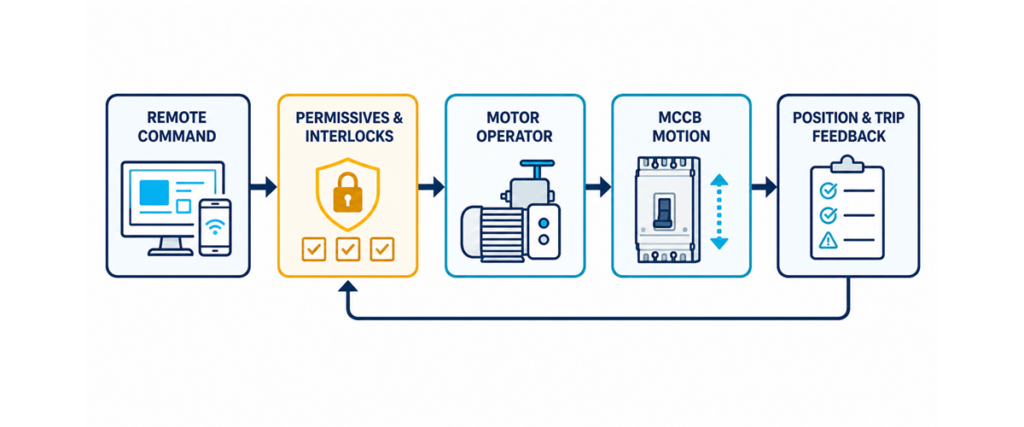
Цепь управления моторным приводом MCCB, показывающая удаленную команду, разрешения и блокировки, движение выключателя, а также обратную связь по положению и отключению.Команда
- Команда может поступать от местных кнопок, выхода ПЛК, реле BMS, контроллера переключения или реле защиты. Определите, ожидает ли механизм импульс, поддерживаемый сигнал или отдельные входы ОТКЛЮЧИТЬ и ВКЛЮЧИТЬ. Не выводите схему из напряжения управления. Команды должны быть взаимоисключающими: если ОТКЛЮЧИТЬ и ВКЛЮЧИТЬ могут быть запитаны одновременно из-за перекрытия реле или ошибки программного обеспечения, цепь должна разрешать конфликт предсказуемо.
Разрешение
- Команда — это запрос, а не полномочие запитывать цепь. Разрешения на включение обычно включают исправное напряжение источника, отсутствие активной блокировки, выключатель не в обслуживании, альтернативный источник разомкнут, причина отключения устранена и селектор в положении УДАЛЕННОЕ. Отключение обычно имеет меньше разрешений, но требуемая логика все равно должна быть в документе причинно-следственных связей проекта, а не в суждении монтажника.
Движение
- После разрешения механизм потребляет управляющее питание и перемещает выключатель. Источник питания должен удерживать напряжение во время этого переходного спроса. Источник, который корректно измеряется в состоянии покоя, может просесть при запуске двигателя, оставив операцию незавершенной. Допустите заявленное производителем время работы плюс запас на контроль и никогда не подавайте быстрые повторные команды для принудительного завершения.
Обратная связь
- Подтвердите физическое состояние после команды. Контакт положения указывает ВКЛ или ВЫКЛ; отдельный аварийный контакт отличает защитное отключение от командированного открытия. Если команда истекла без ожидаемого состояния, поднимите аварию отказа открытия или отказа закрытия и заблокируйте повторные попытки. Это превращает тихий отказ в действенную диагностическую информацию.
Рассчитывайте источник управления по броску при включении, а не по удерживающей нагрузке
Это расчет, который чаще всего пропускают, и он отличает панель, которая работает, от той, которая отказывает периодически. Катушки аксессуаров потребляют два очень разных тока.
- Мощность включения (броска), ВА — кратковременный бросок при запитке катушки и запуске двигателя. Он определяет кратковременную способность, необходимую источнику, и просадку напряжения, которую увидит каждое другое устройство на этом источнике.
- Удерживающая мощность, ВА — непрерывное потребление после запитки. Она определяет установившуюся тепловую нагрузку.
Источник, который комфортно несет удерживающую нагрузку, но проседает при включении, позволит катушке отпасть или вообще не даст ей втянуться. Устройство не неисправно; источник занижен для спроса, длящегося долю секунды.
Пиковый (пусковой) спрос:
Пиковая ВА = Σ (пусковая ВА × количество)
Пиковый ток при напряжении катушки:
Iпик = Пиковая ВА / В
Установившийся (удерживающий) спрос:
Установившаяся ВА = Σ (удерживающая ВА × количество)
Рекомендуемый номинал источника:
Ориентировочный первый проход источника = Пиковая ВА × 1,25
Множитель 1,25 — это ориентировочный допуск, используемый калькулятором JUTRION, а не универсальное требование, указанное в IEC 60947-2. Замените его там, где данные производителя источника питания, контрольного трансформатора, стандарт проекта, режим работы, температура или исследование одновременной работы требуют другого запаса.
Если несколько аксессуаров могут запитываться вместе — моторный привод выполняет свой цикл, пока удерживается расцепитель минимального напряжения — сложите их пусковые значения. Эта комбинация, а не любое отдельное устройство, является худшим случаем. Калькулятор мощности аксессуаров выключателя JUTRION выполняет эти уравнения напрямую.
| Аксессуар | Пусковая мощность (ВА) | Удержание (ВА) | Режим работы |
|---|---|---|---|
| Моторный привод | Прибл. 300–600 | 0 | Потребляет ток только в течение рабочего цикла |
| Независимый расцепитель (MX) | Прибл. 100–300 | 0 | Кратковременный; включается только для отключения |
| Расцепитель минимального напряжения (MN) | Прибл. 200–350 | Прибл. 5–10 | Непрерывно под напряжением |
| Вспомогательный / аварийный контакт | Пренебрежимо малый | Пренебрежимо малый | Беспотенциальный контакт |
Это иллюстративные диапазоны по умолчанию, опубликованные калькулятором JUTRION, а не значения IEC или номиналы заказанных изделий. Потребление катушки зависит от серии, рамки и типа AC или DC, поэтому заменяйте каждое значение по умолчанию на данные из технического паспорта фактически заказанного устройства. Таблица полезна для понимания соотношения включения и удержания, но не для окончательной спецификации трансформатора или источника питания.
Проверьте падение напряжения перед выбором катушки 24 В DC
Низковольтное DC часто указывается для совместимости с шиной ПЛК или резервируемым ИБП источником управления. Для моторного привода это заслуживает второго взгляда: та же мощность при более низком напряжении означает пропорционально больший ток, и падение напряжения растёт вместе с ним.
Для двухпроводной цепи управления DC:
ΔU = 2 × L × I × ρ / A
Где ΔU — падение напряжения в В, L — длина в одном направлении в м, I — рабочий ток в А, ρ — удельное сопротивление меди (около 0,0175 Ом·мм²/м при 20 °C, растёт с температурой) и A — площадь поперечного сечения проводника в мм². Преобразовано для допустимой длины:
Lмакс. = ΔU × A / (2 × I × ρ)
Для иллюстративного сравнения предположим механизм с потреблением включения 450 VA и допустим падение 10%. Значение 450 VA — это сконструированный ввод в типичном диапазоне калькулятора, а не номинал модели JUTRION:
| Напряжение катушки | Ток срабатывания | Допустимое падение | Максимальный кабельный пролет на 2,5 мм² | Максимальная длина кабеля при 6 мм² |
|---|---|---|---|---|
| DC 24 В | 18,8 А | 2,4 В | Прибл. 9 м | Прибл. 22 м |
| DC 110 В | 4,1 А | 11 В | Прибл. 192 м | Прибл. 460 м |
| AC 220 В | 2,0 А | 22 В | Прибл. 768 м | Прибл. 1844 м |
При данных конкретных условиях опция 24 В DC на проводнике 2,5 мм² достигает допустимого падения напряжения в 10 % примерно на девяти метрах. Это не универсальное ограничение длины кабеля: результат напрямую зависит от тока срабатывания заказанного механизма, сечения проводника, температуры, потерь на клеммах и допустимого диапазона рабочего напряжения. Для длинных линий управления сравните использование проводника большего сечения, локального питания у выключателя и более высокого управляющего напряжения.
Именно поэтому катушки аксессуаров предлагаются в таком широком диапазоне напряжений. Моторизованные приводные механизмы JUTRION доступны в AC 110 В, AC 220 В и AC 400 В, а также в DC 24 В, DC 36 В, DC 110 В и DC 220 В, что позволяет выбирать управляющее напряжение под длину кабеля, а не подгонять сечение кабеля под привычное напряжение.
Пример расчёта: 400 A линия с дистанционным моторным приводом
Применение. Выключатель MCCB на 400 A питает насосную станцию от диспетчерской, расположенной примерно в 60 м. Выключатель должен дистанционно открываться, сбрасываться и закрываться. Установлено устройство защиты от пониженного напряжения, чтобы выключатель отключался при пропадании питания управления.
Шаг 1 — перечислите, что может быть под напряжением одновременно. Моторный привод выполняет свой цикл, пока расцепитель минимального напряжения удерживается во включённом состоянии. Оба питаются от одного источника управления, поэтому учитываются оба.
Шаг 2 — задайте иллюстративные входные данные. Предположим моторный привод с током срабатывания 450 VA и током удержания 0 VA, а также устройство защиты от пониженного напряжения с током срабатывания 275 VA и током удержания 7 VA. Эти условные значения находятся в пределах иллюстративных диапазонов калькулятора JUTRION; замените их на данные из технических паспортов заказанных аксессуаров.
Шаг 3 — пиковая потребность.
Пиковая мощность VA = (450 × 1) + (275 × 1) = 725 VA
Шаг 4 — установившаяся потребность.
Постоянная мощность VA = (0 × 1) + (7 × 1) = 7 VA
Соотношение — это урок: мгновенная потребность более чем в сто раз превышает продолжительную.
Шаг 5 — рассчитать источник питания.
Иллюстративное питание = 725 × 1,25 = 906 VA
Шаг 6 — проверить напряжение относительно линии. При DC 24 В пиковый ток составляет 725 / 24 = 30,2 А, и для удержания падения напряжения в 10 % на 60 м потребуется примерно 26 мм² — что непрактично для цепи управления. При AC 220 В пиковый ток 725 / 220 = 3,3 А, и 2,5 мм² с запасом подходит.
Иллюстративный результат: AC 220 В — более практичный вариант для предполагаемой длины 60 м. Трансформатор управления около 1 кВА и проводники 2,5 мм² — это предварительный выбор при заданных параметрах; окончательный выбор зависит от кратковременной регулировки трансформатора, защиты, способа монтажа, температуры, фактических данных аксессуаров и допустимого диапазона напряжения. При DC 24 В данный пример указывает на необходимость локального питания или значительно большего сечения проводника.
Автоматическое включение требует разрешений, блокировок и политики сброса
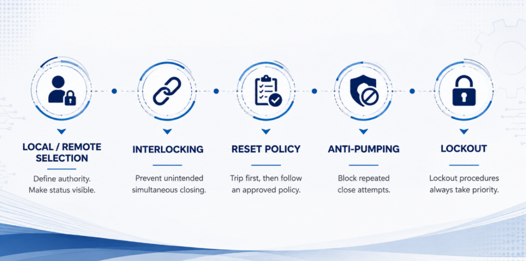
Разрешения на автоматическое включение, блокировка источников, политика сброса, защита от многократных включений и блокировка при обслуживанииДистанционное отключение не вызывает сложностей. Дистанционное включение может подать напряжение на повреждённое оборудование, перезапустить механизмы, параллельно подключить источники или подвергнуть опасности людей, которые считали, что цепь останется разомкнутой. Путь включения заслуживает большего инженерного внимания, чем привод.
Выбор местного/дистанционного управления. Селектор определяет, у кого есть полномочия. Его состояние должно быть видно контроллеру, чтобы заблокированная команда выдавала чёткую индикацию “местный режим”, а не общий сигнал неисправности.
Блокировка источников. Там, где два автоматических выключателя выбирают между питанием от сети, генератора или шин, логика должна предотвращать непреднамеренное одновременное включение, если только система не рассчитана на параллельную работу. Механическая блокировка добавляет физический уровень, но её совместимость должна быть проверена с выбранными выключателями и механизмами.
Политика сброса и повторного включения. Защитное отключение обычно должно блокировать автоматическое включение до классификации причины. Некоторые системы допускают одно контролируемое повторное включение при определённом переходном процессе; другие требуют расследования после каждого отключения. Приводной механизм выполняет утверждённую политику — он не должен создавать её по умолчанию.
Защита от многократных включений. Если команда ВКЛЮЧИТЬ остаётся поданной, пока выключатель отключается, система не должна циклически переключаться между включением и отключением. Архитектура управления должна блокировать повторные попытки до снятия команды и начала новой санкционированной последовательности.
Блокировка при обслуживании. Программная блокировка не заменяет утверждённую процедуру блокировки. Дистанционная система может выдать команды неожиданно во время тестирования, восстановления связи или перезапуска программного обеспечения.
Примените логику к трём распространённым архитектурам
Генератор и переключение источников
Два автоматических выключателя, каждый с приводным механизмом, переключаются контроллером переключения так, что только один из них всегда включён. Приводной механизм необходим, потому что контроллер должен включать включить выключатель, а не просто отключить его.
Контроллер отключает активный источник, подтверждает его отключение через обратную связь по положению и только затем разрешает включение альтернативного источника. Блокировка обязательна. Питание управления также должно быть доступно от любого источника, который находится под напряжением — деталь, которую легко упустить, когда разделительный трансформатор питается только со стороны сети.
Ключевое различие: приводной механизм обеспечивает движение; сам по себе он не делает два выключателя переключателем источников.
Необслуживаемый объект или удалённая подстанция
Автоматический выключатель в помещении на крыше, насосной станции или необслуживаемой подстанции моторизован, чтобы отключение можно было расследовать и восстановить питание без выезда на объект. Кабельная линия обычно длинная, что делает выбор напряжения управления определяющим ограничением, а не механизм. Установите сигнальный контакт рядом с контактом положения, чтобы система управления могла отличить аварийное отключение от отключения по команде, прежде чем кто-либо попытается выполнить дистанционный сброс.
Сброс нагрузки и плановые переключения
Система управления энергопотреблением отключает неответственные фидеры, когда мощность генератора или потребность объекта достигает предела, затем восстанавливает их поэтапно, чтобы избежать второго пика потребления. Каждому фидеру необходим приоритет, минимальное время отключения, разрешение на включение и сигнал неисправности.
Одно отключение и одно включение в день составляет около 10 950 срабатываний за пятнадцать лет. Уточните, как заказанный механизм определяет операцию или цикл, прежде чем сравнивать эту цифру с износостойкостью. Частые плановые переключения могут быть возложены на контактор, а выключатель оставлен для обеспечения защиты и изоляции.
Дооснащение приводным механизмом уже установленного выключателя
Большинство публикаций на эту тему предполагают, что выключатель и комплектующие выбираются вместе. Значительная доля реальных запросов — обратная ситуация: выключатель находится в эксплуатации годами, потребность в дистанционном управлении появилась позже, и вопрос в том, можно ли добавить механизм без его замены.
Некоторые установленные автоматические выключатели в литом корпусе могут принимать механизм дооснащения без замены выключателя. Там, где утверждённый механизм устанавливается спереди, путь тока и уставки расцепления могут остаться неизменными, но панель должна быть изолирована, а состояние выключателя проверено перед установкой. Три вещи определяют целесообразность дооснащения:
- Серия и типоразмер. Механизм подбирается под конкретный выключатель, а не по его номинальному току. Два выключателя на 250 A из разных серий обычно требуют разных механизмов.
- Передний зазор. Приводной механизм увеличивает глубину. Проверьте расстояние до дверцы шкафа и до любой накладки перед заказом.
- Питание управления. В существующем щите может отсутствовать трансформатор управления или DC питание, либо они могут не иметь необходимой выше ёмкости. При модернизации это чаще является реальным ограничением, чем сам механизм.
Бренд не является автоматическим препятствием. Модельная адаптация может охватывать примерно 99 % основных конструкций выключателей, с учётом интерфейса крепления, расположения клемм и напряжения катушки, соответствующих целевому выключателю. Этот процент отражает масштаб программы адаптации, но не означает, что один универсальный механизм подходит для всех MCCB.
Проверка совместимости: запишите производителя автоматического выключателя, серию, габарит и число полюсов, затем предоставьте чёткие фотографии заводской таблички и вида спереди. Эти данные позволяют проверить монтажный интерфейс и рабочий ход до выбора механизма.
Исправный автоматический выключатель может затем получить дистанционное управление без замены, при условии его состояния, наличия свободного места, требуемой документации и одобренного соответствия механизма.
Проверьте варианты вспомогательных принадлежностей
Полный ассортимент принадлежностей для MCB и MCCB может включать моторизованные приводные механизмы, расцепители, реле минимального напряжения, вспомогательные контакты и сигнальные контакты. В таблице ниже сравниваются их функции со стороны управления; механическая совместимость всё ещё должна быть подтверждена по заводской табличке автоматического выключателя.
| Аксессуар | Варианты напряжения управления | Конфигурация | Номинальная выносливость |
|---|---|---|---|
| Моторизованный механизм управления | AC 110 В, AC 220 В, AC 400 В; DC 24 В, DC 36 В, DC 110 В, DC 220 В | Встроенный селектор авто/ручного режима | 10,000 удаленных операций |
| Шунтовый расцепитель (MX / ST) | AC 230 В, AC 400 В; DC 24 В | Мгновенное срабатывание | 4,000 операций срабатывания |
| Расцепитель минимального напряжения (MN / UVR) | AC 230 В, AC 400 В; DC 24 В, DC 48 В | Отключение при 35 %–70 % Un | 4,000 операций срабатывания |
| Вспомогательный контакт (OF) | Без напряжения | 1 NO + 1 NC, или 2 NO + 2 NC | 10,000 электрических циклов |
| Контакт тревоги (SD) | Без напряжения | 1 NO + 1 NC, или 2 NO + 2 NC | 10,000 электрических циклов |
Широкий диапазон напряжений позволяет источнику питания управления следовать за установкой. Внутри одного щита управления DC 24 V может удобно интегрироваться с логикой ПЛК; на длинной линии более высокое управляющее напряжение может снизить требования к проводникам.
Опубликованные данные портфолио указывают 10,000 удаленных операций для категории механизмов и 4,000 операций срабатывания для аксессуаров срабатывания. Подтвердите, как заказанная модель определяет и тестирует операцию перед сравнением с проектной нагрузкой. Используйте контактор где требуется частое рутинное переключение.
Избегайте восьми ошибок, которые приводят к сбоям моторных приводов
| Ошибка | Последствие | Предотвращение |
|---|---|---|
| Указание шунтового расцепителя для “удаленного управления” | Срабатывает удаленно, но должен быть закрыт вручную на панели | Сначала подтвердите, требуется ли удаленное закрытие |
| Предполагая, что удаленное закрытие включает сброс после СРАБАТЫВАНИЯ | Автомат не закроется после срабатывания из-за неисправности | Явно укажите “удаленный сброс после срабатывания” в спецификации |
| Определение источника питания по удерживающим VA | Механизм не срабатывает, периодически | Определите по комбинированному требованию пуска и примените документированную проектную маржу |
| Выбор DC 24 V для длинной линии | Падение напряжения мешает надежной работе; ошибочно диагностируется как неисправный механизм | Проверьте падение напряжения на фактической линии перед исправлением напряжения |
| Игнорирование одновременной работы аксессуаров | Питание, достаточное для одного устройства, проседает, когда два включаются | Добавьте VA пуска всего, что может включаться вместе |
| Подбор только по номинальному току | Аксессуар нельзя установить или он мешает двери | Подтвердите серию, размер рамы и зазор от таблички |
| Пропуск отдельного контакта срабатывания/тревоги | Система не может отличить срабатывание из-за неисправности от командного открытия и может снова замкнуться на неисправность | Установите контакты положения и тревоги и соедините оба |
| Оставление селектора в РУЧНОМ режиме после ввода в эксплуатацию | Удаленные команды игнорируются беззвучно | Проверьте и запишите положение селектора при передаче |
Диагностика сбоев по цепочке управления
| Симптом | Вероятные области | Доказательства для сбора | Безопасное следующее действие |
|---|---|---|---|
| Двигатель не работает | Отсутствие питания, селектор в РУЧНОМ режиме, команда отсутствует, разрешение открыто, предохранитель управления | Напряжение на клеммах питания и управления; состояние селектора и ПЛК | Отслеживайте команду и разрешение перед заменой чего-либо |
| Двигатель работает, автомат не меняет состояние | Механическое несоответствие, неправильная установка, автомат все еще СРАБОТАЛ, неполная перезагрузка | Индикация автомата; ручное движение; выравнивание | Изолируйте управляющее питание и проверьте механический интерфейс |
| Автомат достигает положения, но ПЛК показывает сбой | Неправильный вспомогательный контакт, интерпретация NO/NC, поврежденный провод обратной связи, слишком короткий таймер | Состояние контакта на автомате и контроллере; измеренное время работы | Исправьте логику обратной связи, а не просто увеличивайте таймер |
| Управляющее напряжение падает во время движения | Недостаточный источник питания, длинный провод, маленький проводник, одновременные нагрузки | Минимальное напряжение на механизме во время работы | Исправьте цепь питания, используя данные, специфичные для модели |
| Работает локально, не из диспетчерской | Падение напряжения на длинном проводе, ослабленный зажим на сборочном пункте | Пересчитайте падение при фактическом размере и длине; проверьте окончания | Измените размер проводника или измените управляющее напряжение |
| Автомат повторно закрывается и срабатывает | Устранение неисправности не выполнено, поддерживаемая команда закрытия, отсутствует логика противодействия | Индикация срабатывания, история команд, события защиты | Блокировка повторного закрытия и исследование защищенной цепи |
Не начинайте диагностику с обхода разрешений или принудительного управления. Сначала определите, какая из четырех функций не сработала — команда, разрешение, движение или обратная связь. Это предотвратит путаницу между неисправностью логики управления и механической неисправностью, а также предотвратит повторные операции против заблокированного или сработавшего автомата.
Запишите эти параметры перед выбором механизма
- Фотография таблички с данными автомата — это решает вопрос о бренде, серии, размере и номинале за один шаг
- Бренд, серия и модель автомата, если табличка недоступна
- Количество полюсов и ориентация монтажа
- Необходимые функции: удаленное открытие, удаленная перезагрузка после срабатывания, удаленное закрытие или все три
- Доступное управляющее напряжение, AC или DC, и его источник
- Прокладка кабеля от источника управления к автомату
- Метод команды: импульсный, поддерживаемый или отдельные входы ОТКРЫТЬ и ЗАКРЫТЬ
- Другие аксессуары, установленные одновременно
- Необходимые контакты обратной связи для положения и причины срабатывания
- Ожидаемое количество операций в день или в год
- Что должно произойти, если управляющее питание отключится
- Глубина корпуса и зазор двери
- Целевой рынок и документация, необходимая для проекта
Что должно подтвердить техническое представление
Полезное техническое представление должно идентифицировать точный механизм, соответствующий указанному автомату, а не просто повторять ток автомата. Проверьте обозначение управляющего напряжения, схему входов для открытия и закрытия, возможность перезагрузки, мощность или ток срабатывания, время работы, механическую прочность, схему подключения, общие размеры и совместимую схему вспомогательных контактов. Также должно быть указано, является ли механизм полным фронтальным узлом или требует отдельных кронштейнов, соединителей или проводников.
Для модернизации запросите чертеж, который показывает интерфейс монтажа и добавленную глубину. Для автоматизированного переключения источника или взаимозависимого питания также запросите таблицу истинности команд: какие входы принимаются в состояниях ВКЛ, ВЫКЛ и СРАБОТАЛ, как долго команда должна оставаться активной и что происходит, когда питание исчезает в процессе работы. Эти детали превращают заявление о совместимости в интерфейс, который может проверить производитель панелей.
Если два механизма используют разные значения срабатывания, времена работы или последовательности сброса, они не являются напрямую эквивалентными, даже если оба имеют одно и то же описание продукта. Сравните полную функцию управления и требования к установке, а не только рейтинг привода.
Часто задаваемые вопросы
В чем разница между моторным приводом и независимым расцепителем?
Моторный привод механически размыкает, взводит и замыкает совместимый автоматический выключатель в литом корпусе (MCCB). Независимый расцепитель электрически отключает выключатель при подаче напряжения на его катушку и не может взвести или замкнуть его. В автоматизированных системах часто используются оба устройства, но для разных функций.
Может ли моторный привод перезапустить автоматический выключатель после срабатывания?
Согласованные механизмы могут выполнять сброс, но это зависит от конкретной модели. Убедитесь, что оператор поддерживает дистанционный сброс для вашего конкретного выключателя, и потребуйте, чтобы система управления сняла условие отключения, прежде чем принимать команду на включение.
Можно ли установить моторный привод на автоматический выключатель другого производителя?
Кросс-брендовая установка возможна, если механизм был адаптирован и проверен для целевого автоматического выключателя. Совместимость нельзя установить только по номинальному току. Подтвердите производителя, серию, типоразмер, число полюсов, монтажный интерфейс и рабочий ход по заводской табличке, размерным данным и фотографиям передней панели.
Можно ли добавить моторный привод к уже установленному автоматическому выключателю?
Некоторые установленные MCCB могут принимать привод с фронтальным креплением без замены выключателя. Перед одобрением модернизации проверьте состояние выключателя, серию, рамку, интерфейс рукоятки, фронтальный зазор, точки крепления, питание управления, проводку обратной связи и необходимую проектную документацию.
Какое напряжение управления мне следует выбрать?
Выбирайте напряжение исходя из длины кабеля, а не по привычке. Рассчитайте ток срабатывания при каждом варианте напряжения и проверьте падение напряжения на фактическом расстоянии. В пределах щита DC 24 В удобно; при длинной линии обычно проще использовать катушку на AC 220 В.
Автоматически ли замыкается моторизованный MCCB после аварии?
Не безопасно по умолчанию. Автоматическое закрытие требует утверждённой политики сброса, снятого условия срабатывания, исправных разрешающих сигналов, корректной блокировки и подтверждённой обратной связи. На многих установках после любого защитного срабатывания требуется ручное разрешение.
Финальная проверка проектирования
- Удаленное закрытие действительно требуется, а не только удаленное срабатывание
- Сброс из состояния СРАБОТАЛ явно указан, если автомат должен восстановиться после срабатывания из-за неисправности
- Серия автоматов, размер рамы и монтаж подтверждены по табличке
- Значения срабатывания и удержания VA взяты из технического паспорта, а не предполагаются
- Совокупный спрос на срабатывание рассчитан для всего, что может быть включено одновременно
- Управляющее питание рассчитано на совокупный спрос на срабатывание с учетом запаса, необходимого для выбранного источника, проекта и условий установки
- Напряжение управления выбрано после проверки падения напряжения на фактическом участке
- Поведение при потере источника управления определено, с расцепителем минимального напряжения, если требуется
- Позиция и контакты отключения/сигнализации указаны и подключены
- Разрешения на закрытие, взаимная блокировка и защита от повторного включения определены в логике управления
- Ожидаемое количество операций в год проверено на соответствие номинальной выносливости
- Передний зазор проверен, а положение селектора зафиксировано при вводе в эксплуатацию
Укажите цепь управления перед механизмом
Механизм — это простая часть. То, что определяет, будет ли установка работать, — это все вокруг: удерживает ли источник управления свое напряжение при скачке, многократно превышающем постоянную нагрузку, выживает ли выбранное напряжение катушки на расстоянии и может ли логика отличить сработавший автомат от открытого.
Практический порядок таков: подтвердить необходимость удаленного закрытия, идентифицировать автомат по его табличке, решить, какие движения необходимы, включая сброс, выбрать напряжение управления по кабельному маршруту, определить размер источника по совокупному спросу на подъем, затем установить обратную связь, взаимную блокировку и выносливость.
Для дальнейшего контекста выбора смотрите руководство по аксессуарам для автоматов. Чтобы проверить точное соответствие механизма, предоставьте табличку автомата, фотографию спереди и требования проекта, чтобы можно было рассмотреть полную сборку перед установкой.
Технические ссылки и границы данных
Источники служат различным целям. IEC 60947-2:2024 предоставляет стандартный каркас для низковольтных автоматов; он не упоминается как источник иллюстративного допуска источника 1.25, типичных диапазонов VA аксессуаров, вариантов напряжения управления JUTRION, показателей выносливости или охвата адаптации 99%. Эти значения взяты с текущей страницы аксессуаров JUTRION и калькулятора мощности аксессуаров автоматов. Точные электрические требования, временные параметры, пределы рабочего напряжения и совместимость должны быть указаны в документации на заказанные аксессуары.
- IEC 60947-2:2024 — Низковольтное оборудование и аппаратура управления — Часть 2: Автоматы (шестое издание, сентябрь 2024 года; заменяет пятое издание 2016 года и его Изменение 1:2019). UL 489 применяется к автоматам с корпусом в Северной Америке.
