

ขนาดของกล่องรวมสายโซลาร์เซลล์ที่ต้องการคือเท่าไร? จำนวนสาย, ฟิวส์, ขนาดกระแสและแรงดันไฟฟ้า
คำตอบด่วน: คุณต้องการกล่องรวมโซลาร์ขนาดเท่าใด?
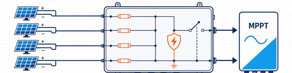
สตริง PV สี่ชุดเชื่อมต่อผ่านกล่องรวมโซลาร์แบบมีฟิวส์ไปยังอินพุต MPPT ของอินเวอร์เตอร์กล่องรวมโซลาร์ควรตรงกับจำนวนสตริง PV ที่เข้ากันได้ที่ป้อนเข้าอินพุตอินเวอร์เตอร์หนึ่งช่อง แรงดันวงจรเปิดสูงสุดในสภาพอากาศหนาวของอาเรย์ กระแสออกแบบรวมตาม Isc และการป้องกันที่จำเป็น ณ ตำแหน่งนั้น จำนวนอินพุตเพียงอย่างเดียวไม่เพียงพอ สี่สตริงอาจต้องใช้กล่อง 4-in/1-out หนึ่งกล่อง วงจร 2-in/1-out สองชุดแยกกัน หรือไม่ต้องใช้กล่องรวมภายนอกเลย ขึ้นอยู่กับอินเวอร์เตอร์และการวางสายเคเบิล.
สำหรับผู้ซื้อ “4 สตริง 1000 V” ฟังดูเหมือนข้อกำหนดที่ใช้ได้ สำหรับวิศวกรที่ตรวจสอบใบเสนอราคา มันเป็นเพียงจุดเริ่มต้น เอกสารข้อมูลโมดูลอาจแสดงว่าสตริงเข้าใกล้ 1000 V ในเช้าที่หนาวเย็น อินเวอร์เตอร์อาจกำหนดสตริงให้กับ MPPT อิสระสองช่อง เส้นทางเอาต์พุตอาจต้องรองรับกระแสเกือบ 70 A หลังจากใช้ค่ากระแสของโครงการแล้ว ข้อเท็จจริงใดข้อหนึ่งเหล่านี้สามารถเปลี่ยนกล่องได้.
เป้าหมายที่นี่คือการเปลี่ยนข้อมูลที่มีอยู่แล้วในเอกสารข้อมูลโมดูล ตารางอินเวอร์เตอร์ และแผนภาพเส้นเดี่ยวให้เป็นข้อกำหนดเบื้องต้นที่สามารถปกป้องได้ สำหรับการกำหนดค่าทั่วไปและตัวเลือกผลิตภัณฑ์ที่มีอยู่ ดูที่ กลุ่มผลิตภัณฑ์กล่องรวม PV JUTRION.
เริ่มจากแบบอินเวอร์เตอร์ ไม่ใช่จำนวนสตริงบนหลังคา
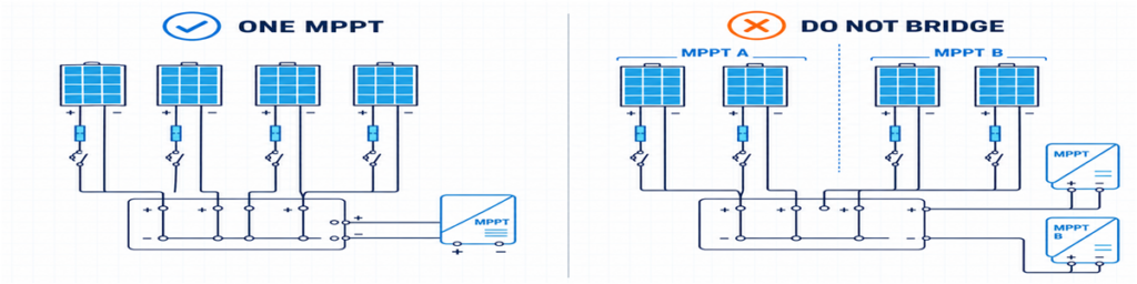
การจัดกลุ่มสตริง PV ที่ถูกต้องสำหรับ MPPT หนึ่งช่อง เปรียบเทียบกับการเชื่อมข้ามอินพุต MPPT แยกกันอย่างไม่ถูกต้องสตริงที่เข้าสู่เอาต์พุตกล่องรวมหนึ่งช่องต้องมีปลายทางที่ถูกต้อง ฟังดูชัดเจน แต่เป็นจุดที่ใบเสนอราคาช่วงแรกหลายฉบับผิดพลาด.
สมมติว่าหลังคามีแปดสตริง แบบอินเวอร์เตอร์กำหนดสี่สตริงให้กับ MPPT A และสี่สตริงให้กับ MPPT B การสั่งกล่องรวม 8-in/1-out จะเชื่อมวงจรสองวงจรที่อินเวอร์เตอร์ถูกออกแบบให้ควบคุมแยกกัน ตัวเลือกที่ใช้ได้จริงคือ กลุ่ม 4-in/1-out สองชุดแยกกัน ตู้หนึ่งที่มีส่วนไฟฟ้าอิสระสองส่วน หรือการเชื่อมต่อสตริงโดยตรงหากอินเวอร์เตอร์มีอินพุตและการป้องกันที่เหมาะสมอยู่แล้ว.
สตริงที่ตั้งใจให้ทำงานแบบขนานควรเข้ากันได้อย่างแท้จริง ตรวจสอบประเภทโมดูล จำนวนโมดูลต่อสตริง การวางแนว และเงาที่คาดว่าจะเกิดขึ้น ความยาวสตริงที่ไม่เท่ากันมีแรงดันใช้งานต่างกัน การรวมสตริงที่มีเงามากและไม่มีเงาเข้าด้วยกันอาจทำให้เกิดการจับคู่การทำงานที่ไม่ดี แม้ว่าฉลากโมดูลจะเหมือนกันก็ตาม.
นี่ให้กฎข้อแรกที่ใช้ได้:
นับสตริงที่กำหนดให้กับเส้นทาง MPPT ที่เข้ากันได้หนึ่งเส้นทาง ไม่ใช่ทุกสตริงที่เห็นในแบบโครงการ.
เมื่อกล่องรวมภายนอกเพิ่มคุณค่าเพียงเล็กน้อย
อินเวอร์เตอร์สตริงหลายรุ่นมีอินพุต DC หลายช่อง การป้องกันไฟกระชากภายใน และฟังก์ชันตัดแยก DC อยู่แล้ว หากแต่ละสตริงสามารถเดินสายตรงไปยังอินพุตอินเวอร์เตอร์ที่เหมาะสม การเพิ่มกล่องรวมภายนอกอาจสร้างจุดต่อสายเพิ่มโดยไม่แก้ปัญหาการออกแบบ.
กล่องสตริงเดี่ยวเป็นกรณีที่เกี่ยวข้องแต่แตกต่าง หน่วย 1-in/1-out ไม่ได้รวมกระแส แต่ทำหน้าที่เป็นกล่องป้องกันและตัดแยกภายนอก ซึ่งมีประโยชน์เมื่ออินเวอร์เตอร์อยู่ไกล จำเป็นต้องมีจุดตัดแยกในพื้นที่ หรือโครงการต้องการการป้องกันไฟกระชากแบบเปลี่ยนได้ในตำแหน่งที่เข้าถึงได้.
ตัวเลขห้าค่าที่ควรใส่ไว้ในแผ่นเดียว
ก่อนดูขนาดฟิวส์หรือขนาดตู้ ให้รวบรวมข้อมูลห้ากลุ่ม ส่วนใหญ่สามารถคัดลอกโดยตรงจากเอกสารโครงการที่ออกแล้ว.
| ข้อมูล | แหล่งที่มาตามปกติ | สิ่งที่มันเปลี่ยนแปลง |
|---|---|---|
| Voc, Isc, Imp, ค่าสัมประสิทธิ์อุณหภูมิ และฟิวส์อนุกรมสูงสุด | แผ่นข้อมูลโมดูล PV | ขีดจำกัดแรงดัน กระแส และฟิวส์สตริง |
| โมดูลต่อสตริงและจำนวนสตริงขนาน | ตารางสตริง | จำนวนอินพุตและแรงดัน/กระแสรวม |
| การจัดเรียง MPPT และขีดจำกัดอินพุต | แผ่นข้อมูลอินเวอร์เตอร์และแผนภาพเส้นเดี่ยว | สตริงใดที่สามารถใช้เอาต์พุตร่วมกันได้ |
| อุณหภูมิต่ำสุด การติดตั้ง และการสัมผัส | เกณฑ์การออกแบบโครงการและข้อมูลสถานที่ | Voc ขณะเย็น การลดค่า และตู้ |
| ประเทศปลายทางและกฎที่เกี่ยวข้อง | ข้อกำหนดโครงการ | วิธีการป้องกันและเอกสาร |
ค่าหนึ่งที่มักถูกมองข้ามคือกระแสลัดวงจรสูงสุดที่อินเวอร์เตอร์ยอมรับได้ กระแสใช้งานสูงสุดและกระแสลัดวงจรสูงสุดไม่สามารถใช้แทนกันได้ ควรตรวจสอบอาร์เรย์ที่เสนอเทียบกับทั้งสองค่า.
ประเทศปลายทางมีความสำคัญไม่แพ้ข้อมูลทางไฟฟ้า การคำนวณฟิวส์ที่เตรียมไว้สำหรับโครงการแนว IEC ไม่ควรยืมตัวคูณของอเมริกาเหนือมาใช้เงียบ ๆ แล้วนำเสนอเป็นกฎสากล.
ตรวจสอบแรงดันสตริงขณะเย็นก่อนเลือก 1000 V หรือ 1500 V
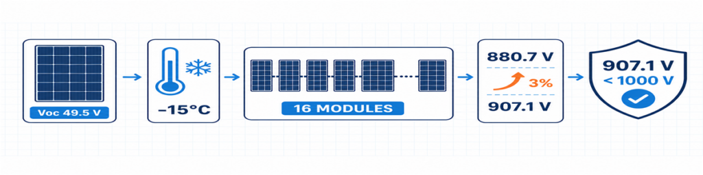
การคำนวณ Voc ของสตริง PV ในสภาพอากาศหนาวสำหรับ 16 โมดูล ได้แรงดันออกแบบ 907.1 Vโดยปกติ Voc ของโมดูลระบุที่สภาวะทดสอบมาตรฐาน ค่านี้จะเพิ่มขึ้นเมื่ออุณหภูมิเซลล์ลดลง ดังนั้นสภาวะที่คาดว่าจะหนาวที่สุดจึงเป็นตัวควบคุมแรงดันสตริงสูงสุด.
ในกรณีที่แผ่นข้อมูลโมดูลระบุค่าสัมประสิทธิ์อุณหภูมิ Voc เป็นลบเป็นเปอร์เซ็นต์ต่อองศาเซลเซียส การคำนวณเบื้องต้นคือ:
Voc,เย็น = Voc,STC × [1 + |βVoc| × (25 − Tmin)]
Vสาย,เย็น = Voc,เย็น × จำนวนโมดูลในอนุกรม
ป้อนสัมประสิทธิ์เป็นทศนิยม เช่น −0.28%/°C ให้ใช้ −0.0028 ในสูตร หากผู้ผลิตโมดูลมีวิธีการอุณหภูมิต่ำที่แตกต่าง ให้ใช้วิธีนั้นแทน
คำตอบต้องครอบคลุมมากกว่าตัวอินเวอร์เตอร์ ฟิวส์ลิงก์และที่ยึด SPD สวิตช์-ตัดวงจรหรือเบรกเกอร์ ขั้วต่อ ตัวนำ และชุดประกอบทั้งหมดอยู่ในวงจร DC เดียวกัน การเปลี่ยน SPD เพียงอย่างเดียวเป็นอุปกรณ์ 1500 V ไม่ได้แปลงกล่อง 1000 V ให้เป็นชุดประกอบ 1500 V
ส่วนต่างแรงดันที่ไม่ได้ใช้เล็กน้อยไม่ใช่ความจุที่สูญเปล่า มันดูดซับพื้นฐานอุณหภูมิและความคลาดเคลื่อนเฉพาะโครงการที่ได้รับการระบุจริง สิ่งที่ควรหลีกเลี่ยงคือส่วนต่างแบบสุ่มที่ไม่มีแหล่งที่มาบันทึกไว้
ฟิวส์สายขึ้นอยู่กับกระแสย้อนกลับ ไม่ใช่นิสัย
เมื่อสายคู่ขนานมีสภาพดี แต่ละสายจะจ่ายกระแสไปยังเอาต์พุตร่วม หากสายใดสายหนึ่งเกิดความผิดปกติ สายอื่นอาจจ่ายกระแสย้อนกลับเข้าไปในสายที่ผิดนั้น ฟิวส์สายมีไว้เพื่อขัดจังหวะกระแสย้อนกลับที่เป็นอันตรายนั้นเมื่อจำเป็นต้องมีการป้องกัน
การคัดกรองเบื้องต้นสำหรับการมีส่วนร่วมจากสายอื่นคือ:
Iย้อนกลับ,คัดกรอง = (n − 1) × Isc,สาย
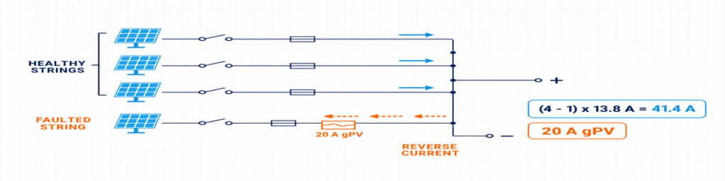
กระแสย้อนกลับจากสาย PV สามสายที่มีสภาพดีเข้าสู่สายที่มีความผิดปกติซึ่งได้รับการป้องกันโดยฟิวส์ gPV ขนาด 20 Aที่นี่ n คือจำนวนสายคู่ขนาน สมการแสดงให้เห็นว่าทำไมคำตอบจึงเปลี่ยนแปลงอย่างรวดเร็วระหว่างสองและสี่อินพุต: สายที่มีความผิดปกติในกลุ่มสี่สายอาจได้รับกระแสจากสายที่มีสภาพดีสามสาย
อย่าถือว่านิพจน์นั้นเป็นการออกแบบการป้องกันที่เสร็จสมบูรณ์ ฟิวส์ gPV ที่เลือกต้องรองรับกระแสที่คาดว่าจะเกิดขึ้นภายใต้สภาพตู้จริง ป้องกันสายเคเบิลและอุปกรณ์ อยู่ภายในพิกัดฟิวส์อนุกรมสูงสุดของโมดูล และมีความสามารถด้านแรงดัน DC ของ PV และความสามารถในการตัดกระแสเพียงพอ ตัวจับฟิวส์และฟิวส์ต้องตรวจสอบร่วมกัน รวมถึงผลกระทบจากอุณหภูมิและการจัดกลุ่ม.
IEC 60269-6 ครอบคลุมข้อกำหนดเสริมสำหรับฟิวส์ลิงก์ที่ใช้ในสายและแผงโซลาร์เซลล์ที่มีแรงดันสูงถึง 1500 V DC กฎการติดตั้งที่นำมาใช้ในโครงการจะกำหนดวิธีการใช้ผลิตภัณฑ์นั้น
เกี่ยวกับตัวเลข 1.56 × Isc ที่พบออนไลน์
ค่า 1.56 × Isc ที่คุ้นเคยเกี่ยวข้องกับปัจจัย 125% สองตัวที่ใช้ในแนวทางการออกแบบทั่วไปในอเมริกาเหนือ ไม่ควรนำไปติดป้ายใหม่ว่าเป็นสูตร IEC สากล หากโครงการอยู่ภายใต้ NEC ให้ใช้ฉบับที่นำมาใช้ รายการอุปกรณ์ที่รับรอง และข้อกำหนดท้องถิ่น หากเป็นโครงการ IEC ให้ใช้กฎการติดตั้งที่อิงตาม IEC ที่เกี่ยวข้อง และคำแนะนำของผู้ผลิตโมดูล ฟิวส์ และสายเคเบิล.
ความแตกต่างนี้ควรระบุในใบเสนอราคา มิฉะนั้น ผู้จัดจำหน่ายสองรายอาจให้ขนาดฟิวส์ที่แตกต่างกันแม้ว่าจะได้รับข้อมูลแผงโซลาร์เซลล์ชุดเดียวกัน
กำหนดขนาดเส้นทางรวมแยกจากแต่ละอินพุต
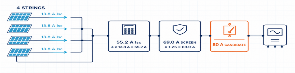
Sาย PV 4 สายที่มีกระแส 13.8 A รวมกันเป็น 55.2 A Isc โดยมีค่ากระแสออกแบบที่ 69 A และอุปกรณ์เอาต์พุตที่เลือกไว้ที่ 80 Aด้านอินพุตและเอาต์พุตมีกระแสที่แตกต่างกัน อินพุตแต่ละตัวรับสายหนึ่งสาย; เอาต์พุตร่วมรับผลรวมของสายขนานทั้งหมด
IIsc,total = จำนวนสายขนาน × Isc,สาย
ปัจจัยการออกแบบและปัจจัยแก้ไขที่โครงการกำหนดจะถูกนำไปใช้กับตัวนำและอุปกรณ์ที่เหมาะสม ผลลัพธ์มีผลต่อการเดินสายภายใน บัสบาร์ ขั้วต่อ สายเคเบิลขาออก และอุปกรณ์สวิตชิ่งเอาต์พุต นอกจากนี้ยังต้องเปรียบเทียบกับขีดจำกัดที่ระบุของอินเวอร์เตอร์ด้วย.
การใช้ Imp เพียงอย่างเดียวสำหรับการเลือกทั้งหมดอาจทำให้เส้นทางการป้องกันเล็กเกินไป การใช้ Isc เพียงอย่างเดียวโดยไม่ตรวจสอบกระแส MPPT ปกติของอินเวอร์เตอร์อาจพลาดข้อจำกัดในการทำงาน เก็บค่าแยกจากกันและกำหนดวัตถุประสงค์ให้แต่ละค่า.
| ค่า | ใช้เพื่อตรวจสอบ |
|---|---|
| ความต้านทานสาย | กระแสทำงานปกติและความเข้ากันได้กับ MPPT ของอินเวอร์เตอร์ |
| กระแสลัดวงจรของสาย | กระแสออกแบบของสายและการคำนวณการป้องกันกระแสเกิน |
| กระแสลัดวงจรรวม | เส้นทางรวมและขีดจำกัดกระแสลัดวงจรของอินเวอร์เตอร์ |
| กระแสออกแบบโครงการที่แก้ไขแล้ว | ตัวนำ, บัสบาร์, เทอร์มินัล และอุปกรณ์เอาต์พุตภายใต้สภาพการติดตั้ง |
ความร้อนสามารถมีผลเหนือกว่าการจัดอันดับในแคตตาล็อกที่ดูเหมือนจะเหมาะสม ตัวถือฟิวส์ที่อยู่ชิดกัน การสูญเสียที่เทอร์มินัล SPD และรังสีแสงอาทิตย์โดยตรงทั้งหมดเพิ่มอุณหภูมิในตู้ อุปกรณ์ 80 A ในสภาพอ้างอิงไม่ได้หมายความว่าจะเป็นโซลูชัน 80 A ในทุกตู้กลางแจ้งโดยอัตโนมัติ
ฟิวส์, การแยกวงจร, เบรกเกอร์ และ SPD มีหน้าที่แตกต่างกัน
กล่องคอมไบเนอร์จะง่ายต่อการกำหนดเมื่อแต่ละส่วนประกอบมีหน้าที่ชัดเจนหนึ่งอย่าง:
- ฟิวส์ gPV: ปกป้องสายแต่ละสายจากสภาวะกระแสย้อนกลับเกินที่เกี่ยวข้อง;
- สวิตช์-ดิสรัปเตอร์: ให้การสวิตช์โหลด DC PV และจุดแยกวงจรที่กำหนด;
- เบรกเกอร์วงจร DC: สวิตช์วงจรและให้ฟังก์ชันป้องกันกระแสเกินเมื่อคุณสมบัติและการจัดอันดับการตัดวงจร DC เหมาะสมกับการใช้งาน;
- SPD DC PV: จำกัดแรงดันเกินชั่วคราวและไม่ทดแทนการป้องกันกระแสเกินหรือการแยกวงจร.
เบรกเกอร์เอาต์พุตไม่จำเป็นเพียงเพราะมีที่ว่าง ระบบอาจออกแบบให้ใช้สวิตช์-ดิสรัปเตอร์เมื่อมีการป้องกันกระแสเกินที่จัดไว้แล้วที่อื่น หรือใช้เบรกเกอร์ที่มีหน้าที่ป้องกันที่กำหนดไว้ ตัดสินใจหน้าที่ก่อน
หลักการเดียวกันนี้ใช้กับ SPD ยืนยันการใช้งาน PV DC, แรงดันไฟฟ้า (U)CPV, โหมดการป้องกัน, ระดับการป้องกัน, หน้าที่กระแสคายประจุ, พฤติกรรมกระแสลัดวงจร และการประสานงานสำรอง ประเภท 2 มักใช้สำหรับสภาวะแรงดันเกินที่เกิดขึ้น เมื่อมีระบบป้องกันฟ้าผ่าภายนอกหรือเส้นทางกระแสฟ้าผ่าอื่น อาจต้องใช้การป้องกันประเภท 1 หรือ ประเภท 1+2 ดูเอกสารอ้างอิงเพิ่มเติม ช่วง SPD DC PV ของ JUTRION หลังจากทราบแรงดันโครงการและบริบทฟ้าผ่าแล้ว
สำหรับฟังก์ชันการแยกวงจร อุปกรณ์ที่จัดอันดับสำหรับหน้าที่ PV ที่ตั้งใจไว้มีความหมายมากกว่าคำอธิบายทั่วไปว่า “สวิตช์ DC” ช่วง อุปกรณ์แยกวงจร DC PV ของ JUTRION รวมตัวเลือก DC-PV2 สำหรับการพิจารณาตามแรงดัน, กระแส และการจัดเรียงขั้วที่ต้องการ
ตัวอย่างสตริงสี่ชุดจาก Datasheet ถึงกล่อง
ตัวอย่างประกอบ: นี่คือตัวอย่างกรณีหลังคาเชิงพาณิชย์ที่สร้างขึ้นเพื่อแสดงการคำนวณ ไม่ใช่โครงการลูกค้าหรือการออกแบบสากล
สตริงสี่ชุดที่เหมือนกันถูกกำหนดให้กับอินพุตอินเวอร์เตอร์กระแสสูงหนึ่งชุด แต่ละสตริงประกอบด้วยโมดูล 16 ตัว Datasheet ของโมดูลระบุ Voc = 49.5 V, Isc = 13.8 A, βVoc = −0.28%/°C และค่ากำหนดฟิวส์อนุกรมสูงสุดที่ 25 A อุณหภูมิต่ำสุดของโครงการคือ −15°C และฐานการออกแบบยังใช้ค่ากำหนดเผื่อ 3% หลังการคำนวณอุณหภูมิ
อินเวอร์เตอร์ตัวอย่างมีแรงดันอินพุต DC สูงสุด 1000 V กระแสอินพุตสูงสุด 80 A และกระแสลัดวงจรสูงสุด 100 A ไม่มีการสมมติระบบป้องกันฟ้าผ่าภายนอก
ภาพวาดชี้ไปที่อินพุตสี่ชุดและเอาต์พุตหนึ่งชุด
สตริงทั้งสี่ใช้โมดูลและความยาวสตริงเดียวกัน และเอกสารอินเวอร์เตอร์อนุญาตให้ป้อนข้อมูลเข้าชุดเดียวกัน สถาปัตยกรรม 4-in/1-out จึงเหมาะสมในขั้นตอนนี้ หากภาพวาดแบ่งเป็นสอง MPPT คำตอบจะกลายเป็นสองกลุ่มอิสระ 2-in/1-out
สตริงเย็นมีแรงดันเปิดวงจร (Voc) ถึง 907.1 V
โมดูล Voc ที่อุณหภูมิเย็น = 49.5 × [1 + 0.0028 × (25 − (−15))] = 55.04 V
สตริง Voc ที่อุณหภูมิเย็น = 55.04 × 16 = 880.7 V
แรงดันออกแบบโครงการ = 880.7 × 1.03 = 907.1 V
ชุดประกอบที่ได้รับการยืนยันที่ 1000 V สามารถผ่านการตรวจสอบเบื้องต้นนี้ได้ เช่นเดียวกับอินเวอร์เตอร์ตัวอย่าง ส่วนต่างที่เหลือประมาณ 93 V โมดูลตัวที่สิบเจ็ดจะเพิ่มผลลัพธ์เป็นประมาณ 964 V ก่อนเผื่อค่าเดียวกันและจะไม่ผ่านตัวอย่างนี้หลังจากเผื่อค่าแล้ว
สตริงขนานทำให้ต้องมีการฟิวส์แยกแต่ละสตริง
สตริงอีกสามชุดสามารถให้หน้าจอกระแสย้อนกลับเริ่มต้นได้:
(4 − 1) × 13.8 = 41.4 A
ค่านั้นสูงกว่าพิกัดฟิวส์อนุกรมสูงสุด 25 A ของโมดูล ดังนั้นในตัวอย่างนี้จึงต้องมีการป้องกันสตริงแต่ละสตริง วิธีการของโครงการให้ค่ากรอบเบื้องต้นของกระแสฟิวส์ขั้นต่ำที่ 1.25 × 13.8 = 17.25 A ฟิวส์ gPV 20 A อยู่ระหว่างค่านั้นกับขีดจำกัดโมดูล 25 A ก่อนที่จะยอมรับ ต้องตรวจสอบตัวจับฟิวส์ การป้องกันสายเคเบิล อุณหภูมิตู้ และความสามารถกระแสต่อเนื่อง.
เอาต์พุตร่วมต้องการฉลากมากกว่า 55.2 A
กระแสลัดวงจรรวมคือ:
4 × 13.8 = 55.2 A
ฐานการออกแบบตัวอย่างใช้ 1.25 × Isc เป็นหน้าจอกระแสเอาต์พุตเบื้องต้น:
1.25 × 55.2 = 69.0 A
สวิตช์-ดิสคอนเนกเตอร์ DC ของ PV ขนาด 80 A เป็นกรอบเริ่มต้นที่สมเหตุสมผล ไม่ใช่ตัวเลือกสุดท้ายโดยอัตโนมัติ พิกัดความร้อนที่ติดตั้ง แรงดัน จำนวนขั้ว และหน้าที่การสวิตชิ่งยังต้องตรวจสอบ ขีดจำกัดกระแสลัดวงจร 100 A ของอินเวอร์เตอร์ผ่านการเปรียบเทียบที่ 55.2 A ขีดจำกัดการทำงาน 80 A ควรเปรียบเทียบกับสี่เท่าของ Imp ของโมดูลจากเอกสารข้อมูลจริง.
กล่องเบื้องต้นตอนนี้มีความเฉพาะเจาะจงพอที่จะทบทวน: อินพุตสี่ชุดที่ฟิวส์แยกกัน เอาต์พุตรวมหนึ่งชุด อุปกรณ์ระดับ 1000 V ทั้งหมด เส้นทางรวมออกแบบรอบหน้าจอ 69 A ที่ระบุ การแยก PV DC และ SPD PV DC ประเภท 2 ที่อยู่ภายใต้การประสานขั้นสุดท้าย
ผลลัพธ์ในหน้าเดียว
การคำนวณง่ายต่อการทบทวนเมื่อสมมติฐาน ผลลัพธ์ และการตรวจสอบที่เหลือถูกรวมกัน นี่คือจุดที่ผู้ซื้อสามารถดูได้ว่าสองใบเสนอราคานั้นอิงตามงานเดียวกันหรือไม่
| รายการเลือก | ผลลัพธ์ประกอบ | สิ่งที่ยังต้องยืนยัน |
|---|---|---|
| การกำหนดค่า | 4 อินพุต / 1 เอาต์พุต | สตริงทั้งสี่ป้อนข้อมูลเข้าที่อินเวอร์เตอร์ที่เข้ากันได้ชุดเดียว |
| แรงดันไฟฟ้าโครงการสูงสุด | 907.1 V | ฐานอุณหภูมิสถานที่ วิธีการเผื่อ และขีดจำกัดอินเวอร์เตอร์ |
| การป้องกันสตริง | การเลือกเบื้องต้น gPV 20 A | อุณหภูมิที่ตัวจับฟิวส์ การป้องกันสายเคเบิล และกฎที่ใช้บังคับ |
| กระแสลัดวงจรรวม | 55.2 A | กระแสลัดวงจรสูงสุดที่อนุญาตของอินเวอร์เตอร์ |
| การคัดกรองกระแสเอาต์พุตเบื้องต้น | 69.0 A | ปัจจัยแก้ไขและอุณหภูมิชุดติดตั้ง |
| การแยกเอาต์พุต | ขนาดเฟรม 80 A เป็นตัวเลือกเริ่มต้น | หน้าที่ DC ของ PV, แรงดัน, จำนวนขั้ว และเรตติ้งกระแสที่ติดตั้ง |
| การป้องกันแรงดันกระชาก | SPD ประเภท 2 สำหรับ PV DC เป็นค่าเริ่มต้น | Ucpv, โหมดการป้องกัน, ระบบป้องกันฟ้าผ่า (LPS) และการประสานงานสำรอง |
| ตัวเรือน | ขั้นต่ำ IP65 สำหรับใช้งานกลางแจ้ง | UV, การกัดกร่อน, ความร้อน, ข้อต่อสาย และการควบแน่น |
การเลือกใช้ระหว่างการกำหนดค่า 1/1, 2/1 และ 4/1
JUTRION แสดงผลิตภัณฑ์ 1000 V DC, IP65 ในการกำหนดค่า 1-in/1-out, 2-in/1-out และ 4-in/1-out ใช้จำนวนอินพุตเพื่อคัดกรองสถาปัตยกรรม จากนั้นยืนยันเรตติ้งที่ได้จากการคำนวณโครงการ.
| การกำหนดค่า | เหตุผลทั่วไปในการคัดกรอง | เหตุผลในการหยุดและพิจารณาใหม่ |
|---|---|---|
| 1 อินพุต / 1 เอาต์พุต | สตริงหนึ่งต้องมีจุดป้องกันและแยกวงจรที่เข้าถึงได้ | ไม่มีการรวมกันเกิดขึ้น; ตรวจสอบว่ากล่องแยกเพิ่มฟังก์ชันที่จำเป็น |
| 2 อินพุต / 1 เอาต์พุต | สองสตริงที่จับคู่กันป้อนอินพุตอินเวอร์เตอร์หนึ่งช่อง | สตริงเหล่านี้เป็นของ MPPT แยกกันหรือเกินขีดจำกัดอินพุตรวม |
| 4 อินพุต / 1 เอาต์พุต | สี่สตริงที่จับคู่กันป้อนอินพุตกระแสสูงที่มีเรตติ้งเหมาะสมหนึ่งช่อง | อินเวอร์เตอร์ต้องการสองกลุ่ม MPPT หรือเส้นทางเอาต์พุตมีเรตติ้งต่ำเกินไป |
ตัวอย่างที่ทำงานชี้ไปที่สถาปัตยกรรม JUPV1000-4/1 แต่ไม่ได้อนุมัติฟิวส์ภายใน อุปกรณ์เอาต์พุต หรือ SPD โดยชื่อรุ่นเพียงอย่างเดียว ส่วนประกอบเหล่านั้นต้องเสนอราคาเทียบกับแรงดันโครงการ 907.1 V การป้องกันสตริง gPV 20 A ที่เสนอ หน้าจอกระแสรวมเบื้องต้น 69 A และสภาพการติดตั้งกลางแจ้ง
การกำหนดค่าสตริงขนาด 1500 V หรือใหญ่กว่าที่กำหนดเองควรได้รับการตรวจสอบส่วนประกอบและการประกอบใหม่ ไม่ควรถือเป็นการเปลี่ยนฉลากของการจัดเรียงสต็อก 1000 V
ตู้กลางแจ้งสามารถเปลี่ยนเรตติ้งกระแสได้
การคำนวณทางไฟฟ้ามักทำในสำนักงานที่ 25°C กล่องอาจใช้งานจริงบนหลังคาที่อากาศร้อนกว่า แสงแดดโดยตรงทำให้ตู้ร้อน และฟิวส์หลายตัวรับกระแสเคียงข้างกัน ความแตกต่างนี้ส่งผลมากกว่าความสะดวกสบายขณะบำรุงรักษา
ความร้อนเกิดขึ้นที่ฟิวส์ เทอร์มินัล ตัวนำ SPD และอุปกรณ์เอาต์พุต อุปกรณ์ที่วางชิดกันมีโอกาสระบายความร้อนน้อยลง ในขณะที่ตู้ปิดผนึกจำกัดการแลกเปลี่ยนอากาศ อุปกรณ์ที่รับกระแสตามที่ระบุภายใต้เงื่อนไขอ้างอิงอาจต้องลดเรตติ้งในประกอบขั้นสุดท้าย นี่คือเหตุผลที่สวิตช์-ตัดวงจร 80 A ในตัวอย่างยังคงเป็นเฟรมเริ่มต้นจนกว่าจะตรวจสอบการจัดวางที่ติดตั้งแล้ว
IP65 มีประโยชน์ แต่ตอบเพียงคำถามการป้องกันการเข้าเท่านั้น ไม่ได้กำหนดโดยอัตโนมัติว่า:
- ทนต่อการสัมผัสรังสีอัลตราไวโอเลตระยะยาว;
- ประสิทธิภาพการกัดกร่อนใกล้ชายฝั่งหรือในบรรยากาศอุตสาหกรรม;
- อุณหภูมิภายในที่ยอมรับได้ภายใต้กระแสเต็มและภาระโซลาร์เซลล์;
- การควบคุมการควบแน่นในระหว่างการร้อนและเย็นรายวัน;
- ความเหมาะสมของกลอนสาย ซีล และวัสดุสำหรับสายที่ติดตั้ง;
- ประสิทธิภาพฉนวนที่ความสูงสูง.
รายละเอียดการติดตั้งก็สำคัญเช่นกัน การเดินสายผ่านด้านบนของตู้กลางแจ้งสร้างเส้นทางน้ำที่แตกต่างจากการเดินสายด้านล่าง กลอนสายที่มีขนาดเล็กเกินไปอาจทำลายซีลหรือให้การรองรับสายไม่เพียงพอ การดัดสายแน่นอาจถ่ายโอนแรงกลไปยังฟิวส์โฮลเดอร์และเทอร์มินัล ควรพิจารณาตู้เป็นชุดประกอบที่ติดตั้งแล้ว ไม่ใช่แค่กล่องพลาสติกหรือโลหะเปล่าที่มีหมายเลข IP
IEC 61439-2:2020 ครอบคลุมชุดสวิตช์เกียร์และคอนโทรลเกียร์ที่มีแรงดันสูงถึง 1500 V DC ความเกี่ยวข้องที่นี่คือเชิงปฏิบัติ: การใช้ส่วนประกอบที่มีเรตติ้งแยกกันไม่ลบล้างความจำเป็นในการตรวจสอบชุดประกอบที่เสร็จสมบูรณ์ รวมถึงการเพิ่มอุณหภูมิ คุณสมบัติไดอิเล็กทริก วงจรป้องกัน ระยะห่าง การเดินสาย และโครงสร้างทางกลตามที่เหมาะสม
ส่งข้อมูลเพียงพอให้ซัพพลายเออร์ตรวจสอบผลลัพธ์
คำถามทางเทคนิคสั้น ๆ มีประโยชน์กว่าฟอร์มสั่งซื้อยาว ๆ แนบแผ่นข้อมูลโมดูลและอินเวอร์เตอร์ และระบุ:
- จำนวนสตริงต่อเอาต์พุตและโมดูลต่อสตริง;
- ค่า Voc, Isc, Imp, βVoc ของโมดูล และฟิวส์อนุกรมสูงสุด;
- อุณหภูมิออกแบบขั้นต่ำและการเผื่อแรงดันไฟฟ้าใด ๆ;
- การจัดเรียง MPPT ของอินเวอร์เตอร์และขีดจำกัดอินพุต;
- แรงดันไฟฟ้าสูงสุดที่คำนวณได้และกระแสออกแบบรวม;
- ฟังก์ชันฟิวส์, การแยกวงจร, เบรกเกอร์ และ SPD ที่ต้องการ;
- ตำแหน่งตู้, ข้อกำหนด IP, สภาพแวดล้อม, การสัมผัสรังสี UV และการกัดกร่อน;
- ขนาดสายไฟ, การตรวจสอบ, ตลาดปลายทาง และปริมาณ.
สำหรับโครงการตัวอย่าง จะเป็น: 4-in/1-out, สตริง 4 ชุดเหมือนกัน ชุดละ 16 โมดูล ป้อนเข้า MPPT เดียว, แรงดันออกแบบโครงการ 907.1 V, ฟิวส์ gPV ขนาด 20 A เบื้องต้น, กระแส Isc รวม 55.2 A, หน้าจอกระแสเอาต์พุตเบื้องต้น 69 A, การแยกวงจร PV DC, การป้องกันฟ้าผ่าประเภท 2 สำหรับ PV DC ที่ประสานกัน และตู้สำหรับใช้งานกลางแจ้ง.
เหตุใดใบเสนอราคา “4-String, 1000 V, IP65” สองชุดจึงอาจไม่เท่ากัน
ใบเสนอราคาหนึ่งอาจใช้ฟิวส์ gPV และที่ยึดที่ได้รับการตรวจสอบสำหรับแรงดันและอุณหภูมิที่ตั้งใจไว้ อีกใบเสนอราคาอาจระบุเพียงกระแสฟิวส์ตามชื่อเท่านั้น กล่องหนึ่งอาจมีสวิตช์โหลดเบรกเกอร์แบบสวิตช์-ตัดวงจร อีกกล่องอาจใช้เครื่องมือที่ออกแบบมาเพื่อการแยกวงจรเป็นหลัก SPD Ucpv, โหมดป้องกัน, พฤติกรรมเมื่อเกิดลัดวงจร และความสามารถในการเปลี่ยนทดแทนอาจแตกต่างกันแม้ทั้งสองใบเสนอราคาจะระบุว่า “Type 2 SPD”
เอาต์พุตร่วมเป็นแหล่งความแตกต่างที่ซ่อนอยู่เปรียบเทียบความสามารถกระแสที่ติดตั้งของบัสบาร์, ตัวนำ, เทอร์มินัล และอุปกรณ์เอาต์พุต ไม่ใช่เพียงแค่ตัวเลขแอมแปร์ที่ใหญ่ที่สุดที่พิมพ์ในรายการวัสดุเท่านั้น ตรวจสอบความจุเทอร์มินัลกับสายไฟออกจริงด้วย ใบเสนอราคาที่ราคาต่ำกว่าในเชิงเทคนิคอาจไม่ถูกกว่า หากต้องเปลี่ยนลูกยาง, ใช้ตู้ที่ใหญ่ขึ้น หรือทำงานซ่อมแซมที่ไซต์
ดังนั้นการเปรียบเทียบที่มีประโยชน์จึงควรทำการปรับมาตรฐานรายการต่อไปนี้ก่อนราคา:
- การจัดเรียงอินพุต/เอาต์พุตและการจัดกลุ่ม MPPT;
- แรงดันไฟฟ้า DC สูงสุดของเส้นทางทั้งหมด;
- ชนิดฟิวส์สตริง, เรตติ้ง และขีดจำกัดโมดูล;
- กระแสรวมและสภาพอุณหภูมิที่ติดตั้ง;
- ฟังก์ชันอุปกรณ์เอาต์พุตและหน้าที่ DC;
- ชนิด SPD, Ucpv, โหมด และการประสานงาน;
- ความจุเทอร์มินัลและลูกยางสายเคเบิล;
- วัสดุตู้และความเหมาะสมกับสภาพแวดล้อม.
การเลือกขั้นสุดท้ายควรอ่านเป็นเส้นทางไฟฟ้าที่เชื่อมต่อเดียว หากใบเสนอราคายืนยันเพียงจำนวนอินพุต, แรงดันไฟฟ้าตามชื่อ และระดับ IP ยังไม่ได้ตอบคำถามเรื่องขนาด
ตรวจสอบตู้หลังการติดตั้ง
การออกแบบที่ถูกต้องยังอาจถูกทำลายโดยขั้วกลับ, การต่อสายหลวม, ลูกยางเสียหาย หรือสตริงที่เชื่อมต่อกับอินพุตผิด การว่าจ้างควรปฏิบัติตามขั้นตอนโครงการและคำแนะนำของส่วนประกอบ โดยวงจร DC ต้องถูกแยกและทดสอบโดยบุคลากรที่มีคุณสมบัติ
ก่อนจ่ายไฟเอาต์พุตรวม ให้บันทึก:
- ตัวตนของสตริง, ขั้ว และแรงดันไฟฟ้าวัดแบบวงจรเปิด;
- ว่าแรงดันไฟฟ้าสตริงที่วัดได้สอดคล้องกับการออกแบบและกันเองอย่างสมเหตุสมผลหรือไม่;
- การขันเทอร์มินัลเสร็จสมบูรณ์ตามแรงบิดที่ระบุ;
- ความต่อเนื่องของสายตัวนำป้องกันและการเชื่อมต่อกราวด์ตามที่ต้องการ;
- ชนิดและเรตติ้งฟิวส์ในทุกช่องที่ติดตั้ง;
- สถานะ SPD และการติดต่อสัญญาณเตือนระยะไกล หากติดตั้งไว้;
- การทำงานและตำแหน่งแสดงของอุปกรณ์แยกวงจร;
- ป้าย, ซีลช่องทางที่ไม่ได้ใช้, การบีบอัดลูกยาง และการปิดตู้.
หลังจากระบบทำงานภายใต้โหลดตัวแทน ให้ตรวจสอบความร้อนผิดปกติ, การเปลี่ยนสี, กลิ่น, การทำงานของฟิวส์ที่ไม่พึงประสงค์ หรือความชื้น หากแผนบำรุงรักษาโครงการใช้เทอร์โมกราฟี ภาพฐานจะมีประโยชน์มากขึ้นเมื่อบันทึกโหลดและสภาพแวดล้อมพร้อมกัน จุดประสงค์ไม่ใช่เพื่อ “พิสูจน์” การออกแบบจากการสแกนครั้งเดียว แต่เพื่อเก็บเป็นข้อมูลอ้างอิงสำหรับการเปรียบเทียบในภายหลัง
IEC 62548-1:2023 ให้บริบทการออกแบบ IEC ที่กว้างขึ้นสำหรับอาร์เรย์ PV รวมถึงการเดินสาย DC, การป้องกัน, การสวิตช์ และการต่อลงดิน ชุดประกอบที่เสร็จสมบูรณ์ยังต้องการการตรวจสอบที่เหมาะสม; IEC 61439-2:2020 ครอบคลุมชุดสวิตช์เกียร์และชุดควบคุมกำลังไฟฟ้าถึง 1500 V DC ข้อกำหนด SPD สำหรับ DC ของ PV จะได้รับการจัดการโดย IEC 61643-31.
เพื่อเปรียบเทียบผลลัพธ์กับการกำหนดค่าของ JUTRION โปรดส่งข้อมูลสายสตริง โมดูลและอินเวอร์เตอร์ อุณหภูมิสถานที่ ข้อกำหนดการป้องกัน และมาตรฐานปลายทางผ่าน หน้ากล่องรวมสาย PV. ซึ่งจะทำให้ทั้งสองฝ่ายมีข้อมูลที่น่าเชื่อถือมากกว่าการพูดคุยแบบ “สี่สตริง ราคาดีที่สุด”
คำถามที่พบบ่อย
ต้องใช้กล่องรวมสายโซลาร์เซลล์กี่สตริง?
ไม่มีขั้นต่ำสากล กล่องรวมสายภายนอกมีประโยชน์เมื่อสตริงที่เข้ากันได้ต้องถูกต่อขนานก่อนเข้าสู่อินเวอร์เตอร์อินพุตหนึ่งช่อง เมื่อช่วยลดความยาวสายเคเบิล หรือเมื่อโครงการต้องการตำแหน่งศูนย์กลางสำหรับฟิวส์ การแยกวงจร การป้องกันไฟกระชาก หรือการตรวจสอบ หากอินเวอร์เตอร์รับสตริงทุกสตริงโดยตรงและมีฟังก์ชันที่จำเป็นอยู่แล้ว อาจไม่จำเป็นต้องมีกล่องรวมสายแยกต่างหาก
ควรใช้ฟิวส์ขนาดใดในกล่องรวมสายโซลาร์เซลล์?
เลือกฟิวส์ gPV ที่ได้รับการจัดอันดับสำหรับ PV จากค่า Isc ของสตริง วิธีการติดตั้งที่ใช้ ความสามารถของสายเคเบิล สภาพแวดล้อม และการจัดอันดับฟิวส์อนุกรมสูงสุดของโมดูล ฟิวส์ต้องสามารถรับกระแสที่คาดไว้โดยไม่ทำงานผิดพลาดในขณะเดียวกันก็ต้องต่ำพอที่จะปกป้องโมดูลและสายเคเบิล ห้ามใช้ 1.56 × Isc เป็นกฎ IEC สากล เนื่องจากการคำนวณขึ้นอยู่กับมาตรฐานปลายทาง
สตริงที่เชื่อมต่อกับ MPPT ต่างกันสามารถใช้กล่องรวมสายเดียวกันได้หรือไม่?
สามารถใช้กล่องรวมสายเดียวกันได้ก็ต่อเมื่อวงจร MPPT ยังคงแยกทางไฟฟ้าอย่างชัดเจน ห้ามรวมเอาต์พุตของกลุ่ม MPPT อิสระเว้นแต่ผู้ผลิตอินเวอร์เตอร์จะอนุญาตสถาปัตยกรรมดังกล่าวอย่างชัดเจน แต่ละกลุ่มควรมีสตริงที่เข้ากันได้ เส้นทางเอาต์พุต และการจัดอันดับของตนเอง
ฉันต้องใช้กล่องรวมสาย PV ขนาด 1000V หรือ 1500V?
คำนวณแรงดันไฟฟ้าวงจรเปิดสูงสุดในสภาพอากาศเย็นของสตริงทั้งหมดและรวมค่ากำหนดที่จำเป็นตามวิธีการของโครงการ เลือกคลาสแรงดันไฟฟ้าที่ทำให้อินเวอร์เตอร์และทุกส่วนประกอบในเส้นทางกล่องรวมสายอยู่ในระดับการจัดอันดับ SPD ขนาด 1500 V เพียงอย่างเดียวไม่ทำให้กล่องที่เสร็จสมบูรณ์เหมาะสมกับแรงดัน 1500 V.
ความแตกต่างระหว่างกล่องรวมสาย PV กับกล่องป้องกัน PV คืออะไร?
กล่องรวมสาย PV รวมอินพุตสตริงที่เข้ากันได้สองสตริงขึ้นไปเป็นเอาต์พุตร่วม กล่องป้องกัน PV แบบ 1-in/1-out ไม่รวมสตริง แต่ให้ตำแหน่งที่สะดวกสำหรับฟังก์ชัน เช่น การแยกวงจร การป้องกันไฟกระชาก หรือการป้องกันกระแสเกินในวงจรสตริงเดียว
เอกสารอ้างอิงทางเทคนิค
