

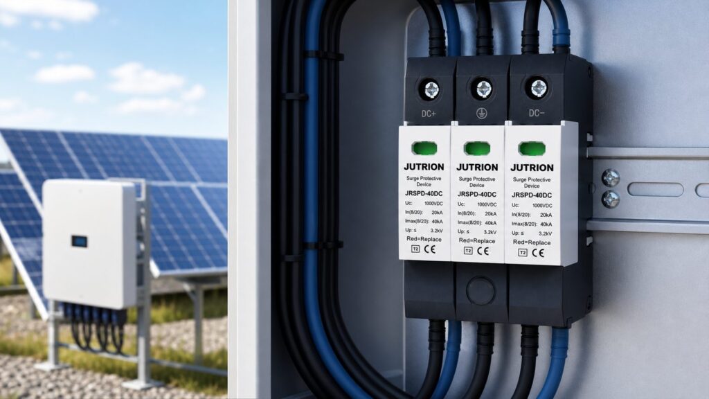
Fast answer: how to specify a DC SPD for a solar array
Choose a DC SPD by four inputs: the array’s maximum open-circuit voltage, its maximum short-circuit current, whether a lightning protection system is present, and the earthing arrangement. Size the maximum continuous operating voltage to Ucpv ≥ 1.2 × the array’s maximum Voc (IEC 61643-32), pick Loại 2 for ordinary rooftops or Loại 1+2 where lightning exposure or an LPS is present, and confirm the device is DC-rated with an integrated thermal disconnector. Match the voltage class to the system: 600 V, 1000 V, or 1500 V.
A DC surge protective device fails in a way an AC one never does. On a cold, clear morning a photovoltaic string sits at its highest voltage of the year, the array is live the instant the sun clears the horizon, and there is no alternating zero-crossing to help extinguish an internal arc. An SPD chosen against the nominal system voltage — “it’s a 1000 V system, so a 1000 V device is fine” — can sit permanently overstressed, drift into leakage, and trip its thermal disconnector months before its rated life. The number that protects the array is not the nominal voltage; it is the array’s real maximum open-circuit voltage plus a margin, and everything else in the specification follows from getting that one figure right.
This guide works through the DC-side selection the way a panel builder or EPC specifier actually does it: establish the array inputs, size the voltage, choose the type, set the protective ratings, then close the loop on fault current, the thermal disconnector, configuration, earthing, the datasheet, the AC side, and lifecycle. It follows the framework of IEC 61643-31 (the product standard for PV DC SPDs) and IEC 61643-32 (selection and application). For the wider view across Type 1, 2, and 3 devices and both AC and DC sides, see the complete surge protective device guide; this article is the DC-side companion that goes deep where a solar array makes the decision different.
Why a DC SPD is not an AC SPD turned sideways
The temptation to reuse a spare AC surge arrester on the PV side is the single most dangerous shortcut in solar surge protection. Alternating current passes through zero one hundred times a second; when a varistor at end of life begins to conduct, that natural current-zero helps the internal disconnector clear the follow current. A photovoltaic array delivers continuous direct current with no zero-crossing at all. A degrading metal-oxide varistor can therefore sustain a DC arc, heat, and become a fire source rather than fail safe.
The protective element itself works the same way in both worlds: a metal-oxide varistor (MOV) is effectively an open circuit at normal voltage and collapses to a low impedance within nanoseconds when the voltage crosses its threshold, diverting the surge to earth and clamping the let-through voltage. Some devices pair the MOV with a gas discharge tube (GDT) in series to eliminate leakage current and improve the failure mode. What changes on the DC side is not the clamping physics but the fault behaviour after the element ages, and that is why the whole device — its voltage rating, its disconnector, and its internal topology — is built for DC.
For that reason a compliant PV DC SPD is built differently. It is rated for continuous DC operation, its modes of protection are arranged for a floating or functionally earthed DC array rather than a neutral-referenced AC supply, and it carries an integrated thermal disconnector that isolates the varistor on failure without relying on a current-zero. IEC 61643-31 is explicit that these devices are dedicated to the DC side of PV generators and inverters — an AC SPD does not meet those requirements and must never substitute. This is a different job from a device that guards against sustained mains over- and under-voltage; if your concern is a slow rise or sag in supply voltage rather than a microsecond transient, that is the domain of an over- and under-voltage protector, not an SPD.
Start with the array: the four inputs that decide the SPD
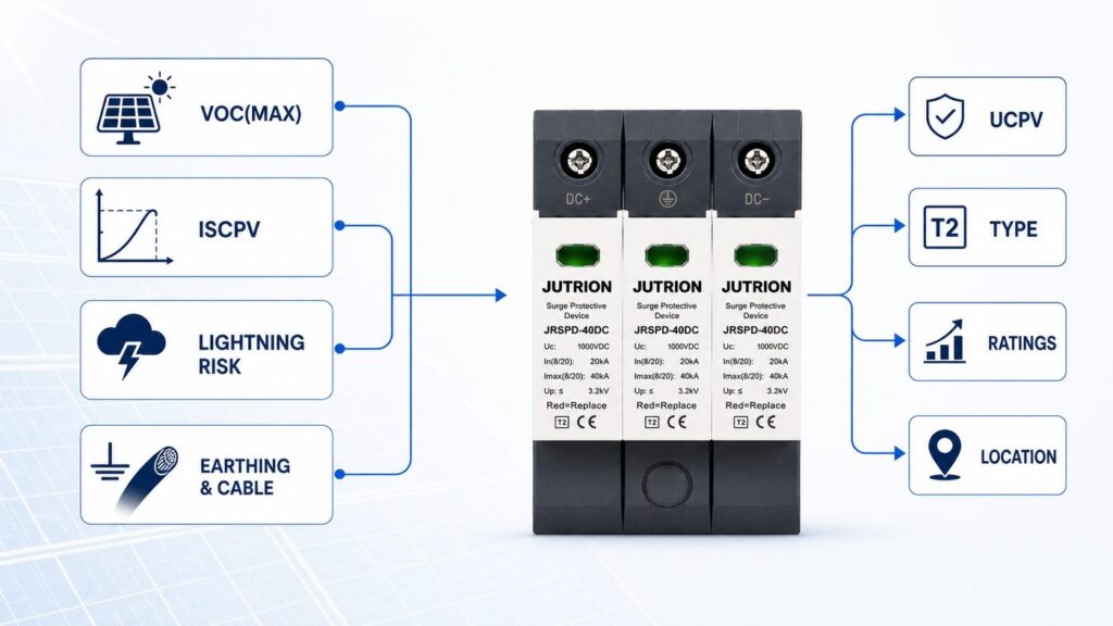
Every rating on the SPD datasheet answers a question about the array. Establish these four inputs before you look at any product:
- Maximum open-circuit voltage, Uoc(max). Not the nominal system voltage — the highest voltage the string can reach, which occurs at open circuit on the coldest expected morning. This sets Ucpv.
- Maximum short-circuit current, Iscpv. The array’s prospective short-circuit current at the SPD’s position, enhanced for irradiance and temperature. This sets the short-circuit withstand requirement and decides whether an external backup device is needed.
- Lightning exposure and LPS presence. Whether the site has a lightning protection system, sits in an exposed or high-flash-density location, or cannot maintain separation distance from down-conductors. This decides Type 2 versus Type 1+2.
- Earthing arrangement and DC cable length. Functionally earthed or floating array, and the cable distance between array and inverter. This decides the SPD’s internal configuration and how many SPD locations the system needs.
Get these four right and the rest of the specification is mechanical. Guess at them and no amount of headline discharge-current rating will save the install.
Sizing Ucpv: the 1.2 × Voc rule and the cold-morning check
Ucpv is the maximum continuous operating voltage the SPD can withstand indefinitely without degrading. Every mode of protection inside the device — positive-to-earth, negative-to-earth, and pole-to-pole — must ride above the array’s highest voltage under all service conditions. IEC 61643-32 states the rule directly:
Ucpv ≥ 1.2 × Uoc(max), where Uoc(max) is the array’s maximum open-circuit voltage at standard test conditions.
The 1.2 factor is not arbitrary padding. Open-circuit voltage rises as cell temperature falls below the 25 °C of standard test conditions, at roughly 0.3 % per degree for crystalline silicon. The 20 % margin absorbs that cold-weather rise for most climates so the SPD is never operated at or above its Ucpv when the array peaks at dawn.
Worked example: a 1500 V-class string
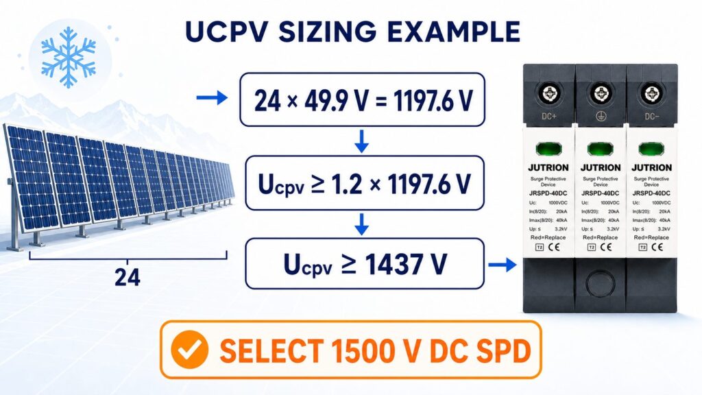
Take a string of 24 modules, each with an STC open-circuit voltage of 49.5 V.
- Array Uoc(max) at STC = 24 × 49.5 V = 1188 V.
- Apply the standard margin: Ucpv ≥ 1.2 × 1188 V = 1426 V.
- Select the next voltage class above that figure: a 1500 V DC SPD (Ucpv rated at 1500 V).
Cross-check the cold morning for an extreme site. At a design minimum cell temperature of −10 °C, the temperature term is a 35-degree drop × 0.3 %/°C ≈ +10.5 %, so Voc rises to about 1188 × 1.105 ≈ 1313 V — still comfortably below the 1500 V Ucpv. For a very cold climate, compute Voc at your own design minimum temperature with the module’s temperature coefficient and confirm Ucpv still clears it; the 1.2 factor covers ordinary conditions, not an Arctic install. Then map to the class shortlist:
- Systems up to ~600 V → 600 V (or higher) Ucpv class.
- 1000 V systems → 1000 V class.
- 1500 V systems → 1500 V class.
Type 2 or Type 1+2? Match the SPD to lightning exposure
The type is a lightning-risk decision, not a quality tier. It follows from the fourth input above and from the site’s lightning protection design.
- Loại 2 devices are tested with the 8/20 µs waveform and rated by nominal discharge current (In) and maximum discharge current (Imax). They handle induced surges and switching transients — the everyday threat on a building rooftop with no external lightning protection system. This covers the majority of residential and commercial rooftop arrays.
- Loại 1+2 devices add a partial-lightning-current rating, the impulse current Iimp tested with the 10/350 µs waveform, while still providing Type 2 protection. Specify them where a lightning protection system is present and separation distance cannot be maintained, on exposed ground-mount and hilltop arrays, and in high lightning-flash-density regions — anywhere a share of direct lightning current can be conducted into the DC side.
The deciding question is whether direct or partial lightning current can reach the array wiring, which is assessed through the site’s lightning protection risk analysis (the IEC 62305 series). If the answer is yes, the extra Iimp capability of a Type 1+2 device is protecting against an energy the Type 2 test does not represent. If the answer is clearly no, a well-specified Type 2 device is the correct and more economical choice, not a compromise.
The DC-side ratings that actually protect the inverter
Once voltage and type are fixed, three ratings determine whether the inverter behind the SPD is genuinely protected:
| Rating | What it represents | Selection rule |
|---|---|---|
| Up (voltage protection level) | The let-through voltage the SPD allows to reach the equipment during a surge | Keep Up at least ~20 % below the impulse withstand voltage (Uw) of the inverter’s DC input, so a margin remains after lead-length losses |
| In (nominal discharge current) | The 8/20 µs current the SPD can divert repeatedly without damage | Higher In gives more headroom and longer service life at exposed sites; treat it as the working rating, not the maximum |
| Imax (maximum discharge current) | The single-event 8/20 µs current the SPD can survive once | A survival ceiling for a severe event, not a duty figure; specify with margin above the expected surge, not equal to it |
Up is the rating that most often gets ignored and most directly decides whether the inverter survives. A device with an impressive Imax but a Up that sits close to the inverter’s withstand voltage lets through a transient the electronics cannot absorb. The JUTRION solar DC range, for example, specifies Up on its 40 kA (8/20 µs Imax) devices so this coordination can be checked against the inverter datasheet rather than assumed.
Coordinate the stages, and check the inverter’s built-in SPD
Two SPD-related questions decide whether extra devices help or simply waste money.
Energy coordination between stages. When a Type 1+2 device at the array or combiner box works together with a Type 2 device at the inverter, the two must be energy-coordinated so the upstream device takes the high-energy hit and the downstream device only trims the residual. Coordination is achieved by keeping enough DC cable between the stages — roughly 10 metres provides sufficient inductive decoupling — or, where that distance is not available, by a decoupling inductor or a manufacturer-verified coordinated set. Mixing two makers’ devices with no defined decoupling can leave the downstream SPD overstressed; follow the manufacturer’s coordination data rather than assuming any two devices cooperate.
The inverter may already contain a DC SPD. Many modern string inverters ship with an integrated Type 2 DC SPD or a slot for a pluggable module. Confirm this before specifying an external device at the inverter DC input: if the inverter already protects its own terminals, the external effort belongs at the array or combiner end, where a long DC home-run is otherwise unprotected. Specifying a second SPD 200 mm from an existing integrated one protects nothing new and adds a failure point.
Fault current, backup, and the thermal disconnector: the safety chain competitors skip
This is where a spec-grade selection separates from a catalogue pick, and where most solar SPD articles go quiet. Three linked requirements keep a failing SPD from becoming a DC fault.
Short-circuit withstand (Iscpv / SCCR)
The SPD must survive the array’s prospective short-circuit current at its installed position. Compare the device’s rated short-circuit withstand current, Iscpv, against the array’s maximum short-circuit current — approximately 1.25 × the modules’ STC Isc for the relevant number of parallel strings, the 1.25 factor covering irradiance and temperature enhancement per PV array design practice (IEC 62548). For a combiner box gathering four parallel strings of modules rated 13.5 A STC short-circuit current, that is 1.25 × 13.5 A × 4 ≈ 68 A; the SPD at that position needs an Iscpv rating at or above roughly 68 A. The SPD’s Iscpv must be equal to or greater than that figure at every location where it is installed.
The integrated thermal disconnector
Because a DC arc has no natural current-zero, IEC 61643-31 requires the SPD to isolate itself on failure. In practice this is a thermal disconnector bonded to the varistor that opens the protection path when the element overheats at end of life. It is a mandatory safety element of a PV DC SPD, not a premium feature — a device without one has no place on the DC side.
When an external backup device is needed
An external backup fuse or DC-rated disconnector is required only when the array’s prospective short-circuit current exceeds the SPD’s Iscpv rating. Many PV DC SPDs are rated to withstand the full string short-circuit current and need no external backup at all; adding an unnecessary fuse only introduces an extra failure point and lead length. Read the SPD datasheet: it states the maximum array short-circuit current the device tolerates unaided and, where a backup is needed, the recommended rating. On larger plants, also specify a device with a remote signaling contact so an operator sees an end-of-life SPD on the monitoring system instead of opening cabinets to eyeball status flags.
Wiring configuration: standard 2-pole versus Y for grounded and floating arrays
PV DC SPDs come in more than one internal topology, and the choice depends on the array’s earthing arrangement. The two you will meet are:
- Standard 2-pole: a varistor from the positive pole to earth and another from the negative pole to earth. Simple and appropriate for functionally earthed systems where that arrangement suits the array.
- Y-configuration (also called 3+0 or total protection): the positive and negative poles each connect through a varistor to a common node, and that node connects to earth through a gas discharge tube (spark gap). Because the spark gap blocks continuous DC to earth, a single failed varistor cannot create a permanent pole-to-earth fault, and the arrangement suits both floating (unearthed) and functionally earthed arrays. It is the configuration most PV DC SPDs use for exactly this reason.
Match the configuration to the array’s earthing arrangement and confirm it against the SPD datasheet; a device chosen only on voltage and current but wired in the wrong topology can leave a mode of protection ineffective or introduce leakage.
Earthing, bonding, and conductor sizing
An SPD is only as good as the earth path it discharges into. The surge current the device diverts has to reach the mass of earth through a low-impedance route, and if that route is long, thin, or loosely terminated, the let-through voltage rises no matter how good the device’s Up is.
- Conductor cross-section. Size the SPD’s connecting and earthing conductors for the surge, not just the working current. Common installation practice (IEC 60364-5-53) is at least 6 mm² copper for a Type 2 device and at least 16 mm² copper for a Type 1 or Type 1+2 device that carries partial lightning current. Confirm the figure against local wiring rules and the SPD instructions.
- Equipotential bonding. Bond the SPD’s earth terminal to the array frame earthing and the main earthing system so that, during a surge, the whole installation rises and falls together and no dangerous potential difference appears across the inverter. On systems with a lightning protection system, this bonding is part of the LPS earthing design, not a separate afterthought.
- Terminations. Keep terminations tight and corrosion-protected in an outdoor combiner box; a high-resistance joint in the earth path quietly defeats the device.
Earthing is the part of the specification a datasheet cannot fix for you. Two identical SPDs, one with a short 16 mm² bonded earth and one with a long undersized tail, protect the inverter very differently.
Where to install, and the two rules that set let-through voltage
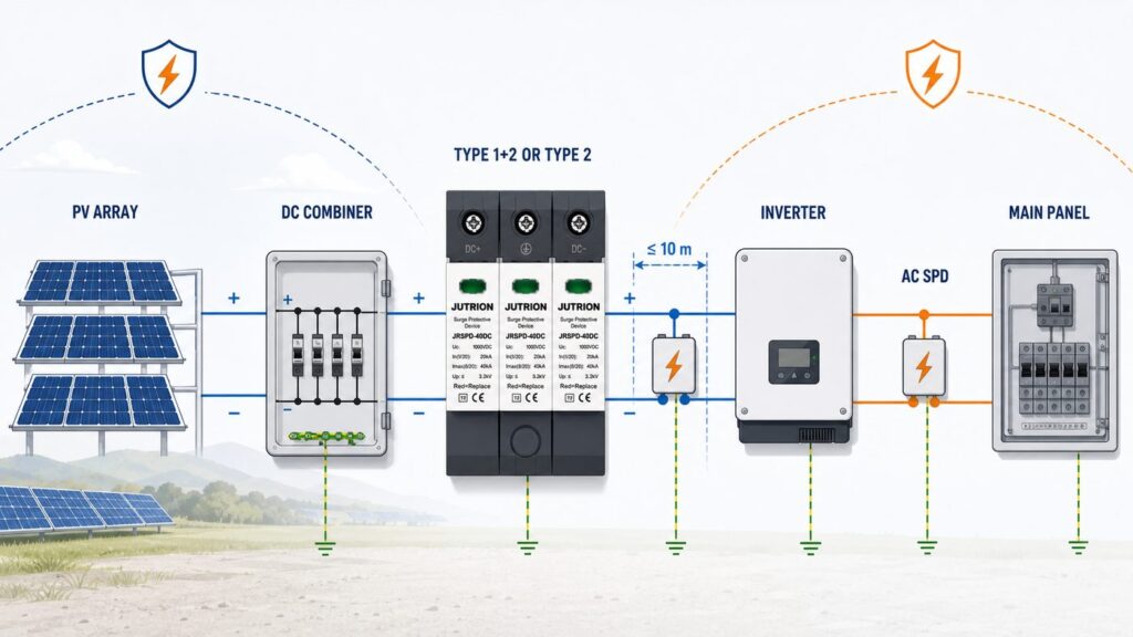
An SPD only protects what sits close to it, so location is part of the specification, not an afterthought.
- At the inverter DC input — unless the inverter already contains a coordinated DC SPD. This is the equipment you are protecting.
- At the array or combiner box — when the DC cable run between array and inverter exceeds roughly 10 metres. Beyond that distance a surge induced on the long DC cable can build enough voltage that one SPD at the far end no longer protects both ends, so protect at both.
- At the combiner and recombiner boxes — on multi-string and large ground-mount systems, one SPD per string group plus the DC disconnect, following the array’s protection zones.
Two installation rules then decide how much voltage actually reaches the equipment:
- The 0.5 m rule. Keep the total connecting-lead length — the loop through the live poles and the earth conductor — to about 0.5 m. Every extra length of lead adds inductive voltage (V = L × di/dt) on top of the device’s Up during a fast surge, so neat cabling routed the long way round the enclosure quietly raises the let-through voltage. Take the shortest path to the busbar and the earth bar.
- Connect earth first. Establish the protective-earth path before the live conductors so the discharge path exists from the moment the SPD is live.
Read the datasheet: a PV DC SPD parameter decoder
A specification is only safe once you can read the datasheet without guessing. These are the lines that matter on a PV DC SPD, and what each one is telling you.
| Datasheet line | What it means | What to check |
|---|---|---|
| Ucpv (Uc DC) | Maximum continuous DC operating voltage | ≥ 1.2 × array maximum Voc, per mode of protection |
| Type / Class | Type 2 (Class II) or Type 1+2 (Class I+II) | Matches the lightning-exposure decision |
| Iimp (10/350 µs) | Partial-lightning impulse current, Type 1 test | Present and adequate only where Type 1+2 is required |
| In (8/20 µs) | Nominal discharge current, repeated duty | Sized to site exposure; the working rating |
| Imax (8/20 µs) | Maximum single discharge current | Comfortable margin above expected surge |
| Up | Voltage protection level (let-through) | ≥ 20 % below the inverter DC withstand voltage |
| Iscpv / SCCR | Short-circuit withstand at the terminals | ≥ array maximum short-circuit current at that point |
| Response time (tA) | How fast the element clamps | Nanosecond-order for MOV-based devices |
| Thermal disconnector / indicator | Internal fail-safe and status window | Present; green/red or flag indication; pluggable module preferred |
| Remote signaling contact | Volt-free contact for monitoring | Specify on large or unattended plants |
| Operating temperature / IP | Environmental range and ingress rating | Suits the combiner-box climate and enclosure |
| Poles / mounting / terminals | 2-pole or Y, 35 mm DIN rail, conductor capacity | Matches earthing arrangement and cable size |
If any of these lines is missing from a datasheet — particularly Ucpv, Iscpv, or the thermal disconnector — treat the omission as a reason to ask, not an assumption to make. A device that will not state its short-circuit withstand or its DC voltage rating is not documented for the DC side.
Don’t forget the AC side: protecting the whole PV system
A PV surge-protection specification that stops at the DC side is only half a specification. The same lightning or switching event that threatens the array reaches the inverter’s AC output and the point of connection to the building or grid, and that side needs its own SPD to IEC 61643-11 — an AC device, sized to the AC system voltage (for example Uc around 275 V line-to-earth on a 230/400 V system), not a DC device.
Coordinate the two sides: a Type 2 AC SPD at the inverter output and main AC board for a building with no external LPS, or a Type 1+2 AC SPD at the origin where an LPS is present, mirroring the logic used on the DC side. JUTRION’s AC range — the JUSPD-40AC (Type 2) and JUSPD-12.5AC (Type 1+2) — covers this side to the same standards, so a single supplier can provide a coordinated DC-and-AC set rather than two unmatched halves.
Monitoring, maintenance, and replacement
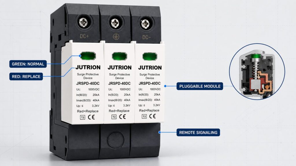
An SPD is a wear part. Every surge it diverts consumes a little of the varistor’s life, and the device is designed to reach end of life and disconnect rather than fail catastrophically. Specifying for that lifecycle is part of selection, not a separate maintenance topic.
- Pluggable modules. Prefer a device with a pluggable protection module and a base that stays wired in. Replacement then takes seconds and does not disturb the DC terminations or the earth path — important on a live PV system that cannot simply be switched off in daylight.
- Status indication. A mechanical flag or a green-to-red window shows at a glance whether the module still protects. On a large or roof-mounted array where no one inspects the combiner box weekly, add the remote signaling contact and wire it back to the monitoring system so an end-of-life module raises an alarm.
- Inspection and replacement. Check the indicators at each scheduled maintenance visit and after any known severe lightning event in the area. When the window shows red or the module has disconnected, replace the module — it no longer protects, even though the array keeps generating. Isolate safely and follow the manufacturer’s live-working guidance before removing a module on an energised DC system.
Designing the array’s protection so a failed module can be seen and swapped quickly is what keeps the protection real years after commissioning, rather than a green light everyone assumes is still green.
Worked example: a 100 kW commercial rooftop
The method comes together on a single realistic project. This case is illustrative, not a specific JUTRION installation, but the arithmetic is the arithmetic you would actually do.
The system. A 100 kWp flat commercial roof, 1500 V string inverters, no external lightning protection system on the building, moderate lightning-flash density. Modules: 550 W, Voc(STC) 49.9 V, Isc(STC) 13.85 A, temperature coefficient of Voc about −0.28 %/°C. Strings of 24 modules, four strings per combiner box, combiner boxes about 15 m of cable from the inverters.
- Voltage. String Voc(STC) = 24 × 49.9 = 1197.6 V. Ucpv ≥ 1.2 × 1197.6 = 1437 V → a 1500 V-class device. Cold check at a design minimum of −5 °C: +8.4 % on Voc ≈ 1298 V, still under 1500 V. The string length is safe for a 1500 V system; a 26-module string would have pushed Ucpv to ~1560 V and out of the 1500 V class.
- Type. No external LPS and a building roof → Loại 2 is correct at both the combiner and the inverter side. A Type 1+2 would be specified only if an LPS were added or the site were highly exposed.
- Short-circuit withstand. Per combiner, four parallel strings: Iscpv ≥ 1.25 × 13.85 × 4 ≈ 69 A. Choose a device whose Iscpv clears 69 A; most will, so no external backup fuse is needed — confirm on the datasheet.
- Locations and coordination. The 15 m run exceeds 10 m, so protect both the combiner boxes and the inverter DC input; the 15 m of cable also provides the decoupling that keeps the two stages energy-coordinated. First, though, check whether the inverters already contain an integrated DC SPD — if they do, keep the combiner-box devices and skip the redundant inverter-input ones.
- Up and earthing. Confirm each device’s Up sits at least 20 % below the inverter’s DC withstand voltage, and earth each SPD with at least 6 mm² copper bonded to the array frame and main earth.
- AC side. Add a Type 2 AC SPD at the inverter AC output / main LV board, Uc about 275 V, to IEC 61643-11.
Result: Type 2, 1500 V-class DC SPDs with Iscpv ≥ ~70 A at each combiner box and (if the inverter has no integrated device) at each inverter DC input, remote signaling on the combiner units for roof-level monitoring, plus a Type 2 AC SPD at the AC board. That is a coordinated, documented specification — not a box picked on discharge current alone.
Selection matrix: from PV system to a specified DC SPD
The matrix below turns the four inputs into a first-pass specification. Read across from the system and its exposure to the type, voltage class, discharge rating, and where the device belongs. Confirm the exact figures against the array calculation and the SPD datasheet before ordering.
| PV system and exposure | SPD type | Ucpv class | Định mức phóng điện | Location |
|---|---|---|---|---|
| Residential rooftop, no external LPS | Loại 2 | Match system (600 / 1000 V) | In sized to exposure; Imax with margin | Inverter DC input; add array end if run > ~10 m |
| Commercial rooftop, no external LPS | Loại 2 | 1000 / 1500 V | Higher In for repeated duty | Inverter DC input and combiner box |
| Commercial rooftop with LPS present | Loại 1+2 | 1000 / 1500 V | Iimp (10/350 µs) plus In/Imax | Inverter DC input and combiner box |
| Exposed ground-mount / hilltop / high flash density | Loại 1+2 | 1500 V | Iimp rated for partial lightning current | Combiner and recombiner boxes; inverter DC input |
| Utility-scale free-field array | Loại 1+2 | 1500 V | High Iimp and In; remote signaling | Every combiner/recombiner and inverter station, per protection zones |
Notice what the matrix does not include: a battery or energy-storage DC bus. IEC 61643-31 and IEC 61643-32 cover the PV generator and inverter DC side up to 1500 V DC; they explicitly do not cover PV systems with energy storage. A battery DC bus needs its surge protection assessed under its own requirements, so do not assume a PV-string SPD is a drop-in for the storage side — specify that separately.
The mistakes that undersize or void a PV DC SPD
Most failed or ineffective PV surge protection traces back to a short list of avoidable errors. Each one has a direct consequence.
- Using an AC SPD on the DC side. No DC-capable disconnector, wrong voltage basis — a fire risk, not a protection device.
- Sizing Ucpv to the nominal voltage. Ignoring the cold-morning Voc rise overstresses the device and trips its thermal disconnector early. Always size to 1.2 × the maximum Voc.
- Over-long or oversized strings. A string whose Voc pushes Ucpv past the 1500 V class leaves no compliant SPD; fix it at design time by shortening the string.
- Ignoring Iscpv. An SPD with a short-circuit withstand below the array’s fault current can fail violently instead of disconnecting cleanly.
- Leads too long. Exceeding the 0.5 m connecting-lead target adds inductive voltage and defeats a low Up.
- Doubling up on an integrated SPD. Fitting an external device beside the inverter’s own coordinated SPD protects nothing new and adds a failure point — put the effort at the unprotected array end.
- Uncoordinated stages. Two SPDs with no decoupling distance or defined inductor can leave the downstream device overstressed. Keep ~10 m between stages or follow the maker’s coordination data.
- No monitoring on unattended arrays. A red window on a rooftop combiner box no one opens means months of unprotected operation; specify the remote contact.
Turn the selection into an RFQ line
A selection is only useful once it becomes something a supplier can quote against without a second round of questions. The reader job at the end of this process is a single, unambiguous specification line. Capture these fields and an enquiry can be answered in one reply:
- Ứng dụng và tiêu chuẩn: Phía DC của hệ PV, theo IEC 61643-31; ghi rõ Loại 2 hoặc Loại 1+2.
- Cấp điện áp hệ thống và Ucpv: cấp 600 / 1000 / 1500 V và Ucpv tối thiểu từ phép tính 1,2 × Voc.
- Voc tối đa của dãy pin: giá trị Ucpv được định cỡ theo đó, để nhà cung cấp có thể xác minh biên độ an toàn.
- Định mức phóng điện: In và Imax yêu cầu (8/20 µs), và Iimp (10/350 µs) đối với thiết bị Loại 1+2.
- Mức bảo vệ điện áp: Up tối đa chấp nhận được, suy ra từ điện áp chịu đựng DC của biến tần.
- Khả năng chịu ngắn mạch: Iscpv tối thiểu từ phép tính ngắn mạch của dãy pin, và liệu có dự kiến thiết bị dự phòng bên ngoài hay không.
- Cấu hình và số cực: cấu hình 2 cực tiêu chuẩn hoặc cấu hình Y, phù hợp với sơ đồ nối đất.
- Điểm lắp đặt và giám sát: đầu vào biến tần, hộp gom, hoặc hộp tái gom; dạng thanh ray DIN; và liệu có yêu cầu tiếp điểm báo tín hiệu từ xa hay không.
Dòng đó loại bỏ sự phỏng đoán ở cả hai phía và là sự khác biệt giữa một bản báo giá và một cuộc trao đổi.
SPD DC khuyến nghị theo loại dự án
Đưa phương pháp trở lại với các quyết định thực tế, đây là cách đặc tả thường được áp dụng cho bốn loại dự án phổ biến, được ánh xạ tới hai dòng sản phẩm DC năng lượng mặt trời JUTRION — JRSPD-40DC-II (Loại 2) và JRSPD-40DC-I+II (Loại 1+2), đều theo IEC 61643-31, lên đến DC 1500 V, Imax 40 kA.
- Biến tần chuỗi áp mái dân dụng (không có LPS): thiết bị Loại 2 (cấp JRSPD-40DC-II) tại đầu vào DC của biến tần, Ucpv phù hợp với Voc buổi sáng lạnh của chuỗi, được định cỡ cho các xung cảm ứng thỉnh thoảng. Thêm một thiết bị thứ hai ở đầu dãy pin chỉ khi đường dây DC dài.
- Áp mái thương mại (không có LPS): Loại 2 tại cả hộp gom và đầu vào DC của biến tần, dòng phóng điện danh định cao hơn cho hoạt động lặp lại, và Up được kiểm tra so với điện áp chịu đựng DC của biến tần.
- Dãy pin mặt đất lộ thiên hoặc dãy pin tiện ích: Loại 1+2 (cấp JRSPD-40DC-I+II) với định mức Iimp thực tế tại các hộp gom và hộp tái gom, cấp 1500 V, và tiếp điểm báo tín hiệu từ xa để giám sát nhà máy — đây là nơi khả năng chịu dòng sét một phần xứng đáng với chi phí của nó.
- Dãy pin có hệ thống chống sét: Loại 1+2 ở bất cứ nơi nào không thể duy trì khoảng cách ly tới các dây dẫn xuống, được phối hợp với thiết kế LPS thay vì chọn riêng lẻ.
Trước tiên hãy xác định bốn đầu vào, định cỡ Ucpv bằng 1,2 × Voc tối đa thực tế, chọn loại theo mức phơi nhiễm sét, sau đó xác nhận Up, khả năng chịu ngắn mạch, bộ ngắt nhiệt, cấu hình và nối đất theo bảng dữ liệu. Nếu bạn muốn các thông số đó được kiểm tra với một dãy pin cụ thể trước khi đặt hàng, thì dòng sản phẩm chống sét AC & DC JUTRION liệt kê dòng DC với các định mức mà hướng dẫn này yêu cầu, và đội ngũ kỹ thuật có thể xác nhận sự phù hợp cho điện áp chuỗi và mức phơi nhiễm tại địa điểm của bạn.
Tài liệu tham khảo
- IEC 61643-31:2018 — Thiết bị chống sét hạ áp, Phần 31: Yêu cầu và phương pháp thử nghiệm đối với SPD dùng cho hệ thống lắp đặt quang điện.
- IEC 61643-32:2017 — Thiết bị chống sét hạ áp, Phần 32: SPD nối với phía DC của hệ thống lắp đặt quang điện, nguyên tắc lựa chọn và ứng dụng.
- Bộ tiêu chuẩn IEC 62305 — Bảo vệ chống sét (đánh giá rủi ro và phối hợp hệ thống chống sét).
- IEC 62548 — Dãy pin quang điện (PV): yêu cầu thiết kế (cơ sở cho dòng ngắn mạch tối đa của dãy pin).
- IEC 60364-5-53 — Hệ thống lắp đặt điện hạ áp: lựa chọn và lắp đặt thiết bị điện, cách ly, đóng cắt và điều khiển (đấu nối SPD và định cỡ dây dẫn).
