

كيفية تحديد حجم ATS لمحوّلات الطاقة الشمسية الهجينة: شرح التحويل بين الشبكة والاحتياطي غير المتصل بالشبكة
لتحديد حجم مفتاح النقل التلقائي (ATS) لعاكس شمسي هجين، حدد أولاً ما سينقله المفتاح فعلياً. لا تختاره بناءً على كيلوواط مصفوفة PV فقط. عند نقطة التركيب، قارن بين أقصى تيار مرور عبر الشبكة، أقصى تيار خرج احتياطي للعاكس، وتيار تصميم لوحة الحمل المنقول. استخدم أعلى تيار يمكن أن يمر شرعيًا عبر ATS، ثم تحقق من ترتيب الأقطاب، واجب القصر، فئة الاستخدام، منطق النقل، والتوافق مع هندسة النسخ الاحتياطي المعتمدة للعاكس.
تكتسب هذه التفرقة أهمية لأن "مرتبط بالشبكة"، "هجين"، و"غير متصل بالشبكة" تصف سلوكيات كهربائية مختلفة. عادةً ما يتوقف عاكس PV التقليدي المتبع للشبكة عن توفير الطاقة أثناء انقطاع الشبكة المستمر. قد يحتوي العاكس الهجين على مرحل نقل داخلي ومخرج احتياطي مخصص. قد يشكل العاكس غير المتصل بالشبكة حافلة AC خاصة به ويستخدم الشبكة أو مولدًا فقط كمدخل بديل. تركيب نفس ATS العام في الأنظمة الثلاثة يمكن أن يسبب تشغيلًا خاطئًا، أحمال احتياطية ميتة، أوامر نقل متضاربة، أو مسار متوازي غير آمن.
يشرح هذا الدليل كيفية تحديد حدود ATS الصحيحة، حساب التيار، وتحديد ترتيب التبديل لكل هندسة. يكمل دليلنا العام دليل تحديد حجم مفتاح النقل التلقائي, ، مع التركيز specifically على الأنظمة الشمسية الهجينة وأنظمة البطاريات الاحتياطية.
إجابة سريعة: أي تصنيف يجب أن يتحكم في حجم ATS؟
يعتمد التيار المسيطر على موقع ATS:
| موقع ATS | المصادر التي يتم اختيارها | أساس التيار | خطأ شائع |
|---|---|---|---|
| قبل مدخل AC للعاكس | الشبكة والمولد | التيار الأقصى المسموح به للدخل أو المرور عبر التيار المتردد، طلب الحمل المنقول، وحد المصدر | تحديد الحجم فقط من كيلوواط خرج العاكس |
| بعد الخرج الاحتياطي | الخرج الاحتياطي للعاكس وتجاوز الشبكة | أعلى تيار موثوق يُسلَّم إلى لوحة الأحمال الاحتياطية | استخدام قدرة مصفوفة PV بالكيلوواط بدلاً من تيار لوحة النسخ الاحتياطي |
| حدود خدمة المبنى بالكامل | مصدر المرافق والجزيرة المقصودة | حساب الخدمة/الحمل بالإضافة إلى تصنيف واجهة النسخ الاحتياطي المعتمد | إضافة ATS عام إلى نظام يتطلب واجهة نسخ احتياطي مدرجة |
| ناقل التيار المتردد خارج الشبكة | العاكس والمولد أو تجاوز المرافق | الحد الأقصى لتيار الحمل المنقول والحدود المستمرة لكلا المصدرين | السماح لوحدتي تحكم مستقلتين بتوصيل المصادر دون تعشيق منسّق |
يجب ألا يكون حجم الإطار المختار أقل من التيار التصميمي الأقصى المار عبر المفتاح. ومع ذلك، لا تكفي الأمبيرات وحدها لإكمال المواصفة. يجب أن يتناسب ATS النهائي أيضًا مع جهد النظام، وعدد الأطوار، وترتيب النيوترال والتأريض، ومستوى الخطأ المتوقع، وطريقة النقل، وقواعد التركيب المعمول بها.
ابدأ بالهندسة المعمارية، وليس من كتالوج ATS
قبل حساب التيار، ارسم خطاً واحداً من كل مصدر محتمل إلى الأحمال. حدد نقطة اتصال المرافق، ومدخل شبكة العاكس، والخرج الاحتياطي للعاكس، والبطارية، والمولد، ولوحة الأحمال الأساسية، وكل جهاز قادر على فتح أو إغلاق مسار مصدر. إذا كانت آلية التبديل، ووحدة التحكم، واستشعار المصدر، والتعشيق لا تزال غير مألوفة، راجع كيف يعمل مفتاح النقل التلقائي وكيفية اختياره قبل الانتهاء من مخطط الخط الواحد. يجب أن يجعل الرسم من المستحيل توصيل المرافق ومصدر جزيرة غير متزامن معاً.
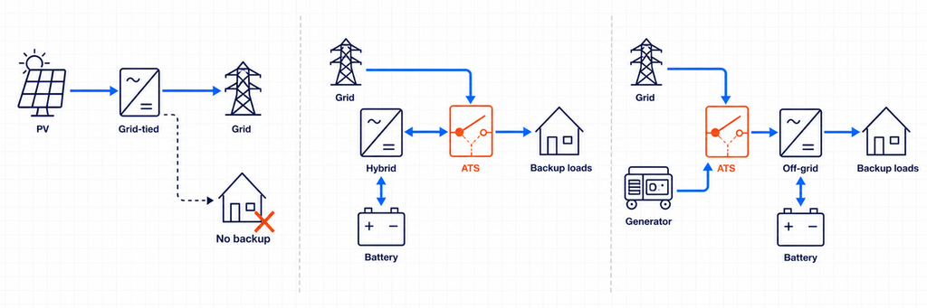
تفرق وزارة الطاقة الأمريكية بين العواكس المتبعة للشبكة، التي تتطلب شبكة عاملة، والعواكس المكونة للشبكة التي يمكنها العمل عند عدم توفر الشبكة. كما تشير إلى أن العواكس المتصلة بالشبكة العادية تنفصل أثناء الاضطرابات الكبيرة أو المستمرة في الشبكة. لهذا السبب، لا يمكن لـ ATS تحويل عاكس متصل بالشبكة عادي إلى مصدر نسخ احتياطي. يتطلب النسخ الاحتياطي المقصود عاكسًا وترتيب عزل مصممين خصيصًا للتشغيل في الجزيرة.
الهندسة المعمارية 1: عاكس PV متصل بالشبكة تقليدي بدون نسخ احتياطي
يعمل عاكس PV المتصل بالشبكة التقليدي بالتوازي مع المرفق ويصدر أو يعوض الطاقة طالما أن الشبكة سليمة. أثناء الانقطاع، تفصل حماية منع الجزيرة العاكس. لا يوجد مصدر تيار متردد بديل مستقر يمكن لـ ATS اختياره.
في هذه الهندسة، لا يؤدي تركيب ATS بين المرفق والمنزل إلى استمرار تشغيل نظام PV. لا يزال العاكس يحتاج إلى مرجع شبكة صالح ولا يُسمح له بتغذية دائرة معزولة ما لم يكن مصممًا ومعتمدًا لتشكيل تلك الجزيرة. إذا كان النسخ الاحتياطي أثناء الانقطاع مطلوبًا، يجب تغيير هندسة النظام: عادةً بإضافة بطارية متوافقة، وظيفة عاكس مكون للشبكة، واجهة نسخ احتياطي، وحدود الحمل الأساسي.
البنية 2: عاكس هجين مع جهاز نقل داخلي
يحتوي العديد من العواكس الهجينة على أطراف منفصلة للشبكة والنسخ الاحتياطي. داخليًا، يعزل جهاز النقل المرفق ويزود مخرج نسخ احتياطي مخصص من البطارية والعاكس أثناء الانقطاع. في هذه الحالة، تحدد وثائق العاكس - وليس مخططًا عامًا - ترتيب النيوترال المسموح به، أجهزة الحماية، حجم لوحة النسخ الاحتياطي، تسلسل إعادة الاتصال، وما إذا كان يُسمح باستخدام ATS خارجي.
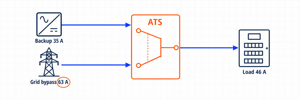
قد يخدم ATS إضافي غرضًا مشروعًا. على سبيل المثال، يمكنه تجاوز عاكس فاشل وإعادة توصيل لوحة الحمل الأساسي مباشرة بالمرفق. في هذا الترتيب، لا ينشئ ATS الجزيرة الشمسية. إنه يختار بين مخرج النسخ الاحتياطي للعاكس وتجاوز الشبكة. لذلك يجب أن يغطي تصنيف تيار ATS الحد الأقصى للتيار المتاح في أي من هذين المسارين.
تستخدم بعض المنصات الهجينة بدلاً من ذلك وحدة تحكم نظام مخصصة أو واجهة نسخ احتياطي تحتوي بالفعل على وظيفة النقل. قد يؤدي استبدال أو تكرار تلك الوظيفة بـ ATS عام إلى تعطيل مراقبة النظام، التحكم في النيوترال، منطق منع الجزيرة، أو شهادة الشركة المصنعة. اعتبر "مفتاح النقل الداخلي"، "واجهة النسخ الاحتياطي"، و"ATS التجاوز الخارجي" كمكونات مختلفة حتى يثبت مخطط الخط الواحد المعتمد خلاف ذلك.
الهندسة المعمارية 3: عاكس خارج الشبكة أو مكون للشبكة مع دخل تيار متردد بديل
عادةً ما يحدد العاكس خارج الشبكة الجهد والتردد لناقل التيار المتردد المحلي. قد يتصل مرفق أو مولد بدخل التيار المتردد بحيث يمكن للعاكس/الشاحن نقل الأحمال، شحن البطارية، أو دعم الطاقة. يحتوي العديد من العاكسات/الشواحن بالفعل على مرحل نقل داخلي. إذا استخدم التصميم ATS خارجي، فقد يختار بين المرفق والمولد عند دخل العاكس، أو مخرج العاكس مقابل مصدر تجاوز عند لوحة الحمل.
هاتان الموضعان غير قابلين للتبادل. يرى ATS على جانب الدخل التيار المقبول والمار عبر العاكس/الشاحن. يرى ATS التجاوز على جانب المخرج التيار المطلوب من الأحمال المنقولة. قد يحتاج جهاز التحكم على جانب الدخل أيضًا إلى جهات اتصال بدء/إيقاف المولد، وقت تسخين، نوافذ قبول الجهد والتردد، وتسلسل تبريد. يجب على جهاز جانب المخرج تجنب تغذية مخرج العاكس عكسيًا عندما يكون التجاوز نشطًا ما لم يسمح تصميم الشركة المصنعة بذلك صراحة.
القيم الأربع للتيار التي يجب تسجيلها
يسجّل ورقة الاختيار الموثوقة أربع قيم للتيار بدلاً من رقم واحد للطاقة الشمسية.
تيار تصميم الأحمال المنقولة
هذا هو التيار المطلوب من الأحمال المتصلة بعد ATS. ليس بالضرورة تصنيف الخدمة الرئيسي ولا تصنيف العاكس تلقائيًا. قد يحمل مفتاح النقل الكامل للمبنى الطلب المحسوب للمبنى. قد يحمل ATS الحمل الأساسي فقط التبريد، الإضاءة، التحكم، الاتصالات، المقابس المختارة، والدوائر ذات الأولوية الأخرى.
استخدم حساب أحمال المشروع وقانون الكهرباء المعمول به. احتسب الأحمال المستمرة والمحركات والمحولات والضواغط والتشغيل المتزامن. إذا كان تخفيف الأحمال جزءًا من التصميم، فوثّق الأحمال التي تُفصل قبل استخدام الرقم المخفّض.
الحد الأقصى لتيار الخرج الاحتياطي للعاكس
اقرأ ورقة بيانات العاكس أو دليل التثبيت. فضل التيار المستمر الأقصى المعلن لمخرج النسخ الاحتياطي على حساب من تصنيف القدرة التسويقي. إذا كانت القدرة الظاهرة فقط متاحة، فالحسابات الأساسية للتيار المتردد هي:
أحادي الطور: I = S ÷ V
ثلاثي الطور: I = S ÷ (√3 × V)
لخرج أحادي الطور 10 kVA، 230 V، التيار المثالي حوالي 43.5 A. لخرج ثلاثي الطور 30 kVA، 400 V، حوالي 43.3 A لكل طور. هذه القيم نقاط بداية، وليست إذنًا لتجاهل حد التيار، منحنى التحميل الزائد، حد عدم توازن الطور، أو تخفيض درجة الحرارة المحيطة من الشركة المصنعة.
تيار المرور عبر الشبكة أو تيار التجاوز
هذه القيمة غالبًا ما تكون القيمة المسيطرة. قد يسمح العاكس الهجين المصنف بقدرة 8 kW من الخرج الاحتياطي بمرور تيار شبكة أكبر عبر مرحلته الداخلية أثناء توفر المرافق. وبالمثل، قد يغذي مسار التجاوز الخارجي لوحة الحمل الأساسية بالكامل مباشرة من الشبكة.
إذا كان يمكن أن يمر 63 A عبر ATS في وضع الشبكة، فإن اختيار ATS بقدرة 40 A لأن العاكس ينتج فقط 8 kW غير صحيح. لا تزال جهات اتصال ومسامير المفتاح تحمل مسار 63 A. سجل الحد الأقصى لتيار الدخل/المرور للعاكس، تصنيف قاطع التجاوز، وحساب الحمل التالي، ثم استخدم التصميم المنسق الأكثر تقييدًا.
الحد الأقصى للتيار المسموح به من كل مصدر وجهاز حماية
يحدد المغذي الكهربائي، وقاطع المولد، وحماية خرج العاكس، والموصلات، والجهاز الرئيسي في لوحة التوزيع الحدود. لا يخلق ATS سعة مصدر إضافية، وتصنيفه للتيار لا يحمي الكابلات بمفرده. يعتمد مفتاح التحويل من فئة PC عادةً على حماية التيار الزائد المنسقة في الأعلى؛ بينما يدمج ترتيب فئة CB وظائف قواطع الدائرة. اختر وتحقق من سلسلة الحماية بالكامل.
طريقة عملية لتحديد حجم ATS للعاكسات الهجينة
- تأكد من أن العاكس يمكنه تشكيل جزيرة. إذا كان النظام PV فقط ومتبعًا للشبكة، توقف: لا يوجد مصدر نسخ احتياطي صالح لـ ATS.
- استخدم الهيكل المعتمد من الشركة المصنعة. حدد واجهة الاحتياطي المطلوبة، ومرحلة التحويل الداخلية، والمفتاح الخارجي المتوافق، أو ترتيب التجاوز المسموح به.
- حدد موقع ATS. اذكر بالضبط أي مصدرين يتصلان بالمصدر I والمصدر II، وأي لوحة تتصل بالخروج المشترك.
- عرّف الأحمال المنقولة. استخدم جدول الأحمال الأساسية أو حساب الطلب على المبنى بالكامل بدلاً من إضافة لوحات أسماء الأجهزة بشكل عشوائي.
- سجل تيار الخرج الاحتياطي. استخدم الحد الأقصى المعلن عنه للتيار ودوّن قدرة الحمل الزائد لفترة قصيرة بشكل منفصل.
- سجل تيار المرور عبر الشبكة أو تيار التجاوز. تحقق من حد إدخال العاكس، وتصنيف المرحل الداخلي، ومغذي التجاوز، والجهاز الرئيسي في اللوحة.
- اختر التيار المستمر. يجب أن يحمل ATS الحد الأقصى للتيار المحتمل في موقعه المثبت، مع مراعاة قواعد الكود، والتخفيض، ودرجة حرارة الحاوية، وتعليمات الشركة المصنعة.
- أكمل الفحوصات غير المتعلقة بالأمبير. تحقق من الجهد، التردد، المراحل، الأقطاب، معالجة المحايد، تصنيف الدائرة القصيرة، فئة الاستخدام، زمن النقل، الاستشعار، جهد التحكم، والتداخل.
- تحقق من كل حالة تشغيل. راجع تشغيل الشبكة العادي، فشل الشبكة، فشل العاكس، نفاد البطارية، تشغيل المولد، تجاوز الصيانة، وعودة الشبكة.
مثال عملي: 8 kW عاكس هجين مع تجاوز الشبكة
اعتبر نظامًا توضيحيًا أحادي الطور 230 V بهذه القيم التصميمية:
- تصنيف احتياطي العاكس الهجين: 8 kVA مستمر
- الحد الأقصى المعلن لتيار الخرج الاحتياطي: 35 A
- الحد المسموح به لتيار المرور عبر الشبكة: 63 A
- تيار تصميم لوحة الحمل الأساسي: 46 A عندما تكون الشبكة متاحة
- حد إدارة الحمل في وضع الاحتياطي: 32 A
- موقع ATS الخارجي: خرج احتياطي العاكس مقابل تجاوز الشبكة المباشر
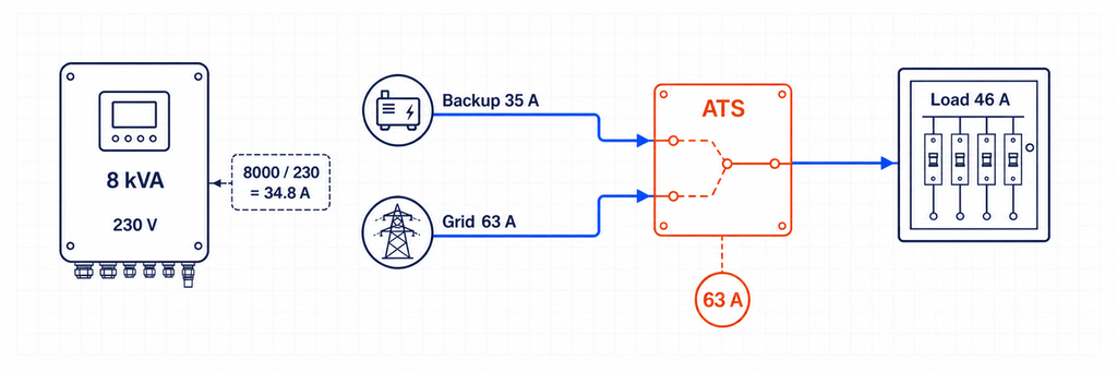
التيار التقريبي للعاكس من القدرة الظاهرة هو 8,000 ÷ 230 = 34.8 A، متسق مع الخرج المعلن 35 A. لكن ATS بقدرة 40 A ليس مناسبًا تلقائيًا. في وضع تجاوز الشبكة، قد تسحب لوحة الحمل الأساسي 46 A والطريق المصدر مسموح له حتى 63 A.
في هذا الموقع، يتم التحكم في اختيار تيار ATS بواسطة تجاوز الشبكة وطريق الحمل المنقول، وليس خرج العاكس بقدرة 8 kVA. قد تكون فئة 63 A هي الحد الأدنى من فئة التيار العملية إذا سمحت جميع الفحوصات المتعلقة بالحمل المستمر، ودرجة الحرارة، والحاوية، والتوصيل، والقوانين المحلية بذلك. يمكن اختيار إطار بقدرة 80 A حيث يتطلب التصميم المنسق، أو تخفيض درجة الحرارة، أو إنهاء الموصل، أو معيار المشروع هامشًا أكبر. لا يمكن الحصول على الإجابة النهائية من 8 kW وحده.
يجب أن يحافظ جهاز التحكم في إدارة الحمل على الطلب في وضع الاحتياطي ضمن قدرة العاكس البالغة 35 A. إن زيادة حجم ATS إلى 63 A أو 80 A لا تجعل العاكس قادرًا على توفير 46 A أثناء انقطاع التيار. هذه قيود منفصلة على الطاقة وإدارة الطاقة.
نقل كامل للمنزل أو نقل الحمل الأساسي؟
يغير هذا الخيار كل من حجم ATS وسلوك النظام. يضع ترتيب النقل الكامل للمنزل حدود الاحتياطي حول معظم أو كل توزيع المبنى. قد يحتاج ATS والواجهة المرتبطة إلى مطابقة الخدمة أو الطلب المحسوب، حتى عندما يمكن للعاكس توفير جزء فقط من ذلك التيار. يعتمد نجاح الاحتياطي الكامل للمنزل عادةً على إدارة الحمل التلقائية التي تفصل تسخين المياه، وتكييف الهواء الكبير، وشحن السيارات الكهربائية، والطهي الكهربائي، أو الأحمال الأخرى قبل أن يتم تحميل العاكس بشكل زائد.
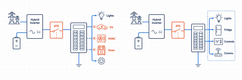
يخلق ترتيب الحمل الأساسي لوحة فرعية أصغر. فقط الدوائر المختارة تنتقل إلى طاقة العاكس. غالبًا ما يسمح ذلك بتصنيف تيار ATS أقل، وموصلات أصغر، واستقلالية بطارية أكثر قابلية للتنبؤ. كما يجعل حد تيار وضع النسخ الاحتياطي مرئيًا: إذا كانت اللوحة تحتوي على 32 A من الطلب المدارة، يمكن للمصمم التحقق من ذلك مقابل خرج العاكس المعلن بدلاً من الأمل في أن يتجنب السكان الأحمال المتزامنة.
استخدم القرار التالي:
- اختر لوحة حمل أساسي عندما يكون خرج العاكس أقل بكثير من سعة الخدمة، تكون طاقة البطارية محدودة، أو تكون أولوية الحمل الموثوقة أكثر أهمية من الراحة.
- اعتبر النقل الكامل للمنزل عندما يدعم ذلك وحدة تحكم النظام المعتمدة، ويمكن للعاكس والبطارية تحمل الطلب المقصود، ويتم توثيق فصل الحمل التلقائي.
- لا تقلل من تيار ATS لمجرد أن برنامج وضع النسخ الاحتياطي يحد من العاكس. إذا كانت نفس جهات الاتصال تحمل الطلب الكامل لوضع الشبكة، فقم بحجمها لمسار الشبكة ذلك.
للمشتريات، اذكر الرقمين: "تيار ATS المستمر عند الحد المثبت" و"أقصى حمل مسموح به في وضع النسخ الاحتياطي". يجيبان على أسئلة مختلفة ويمنعان المثبتين من اعتبار مفتاح كبير الحجم دليلًا على سعة عاكس كافية.
تحتاج العواكس الهجينة ثلاثية الطور إلى فحوصات إضافية
تفترض حسابات التيار ثلاثي الطور توازن القدرة الظاهرة. قد تكون لوحات النسخ الاحتياطي الحقيقية غير متوازنة، ويفرض بعض العواكس الهجينة حدًا أقصى للتيار لكل طور أو حدًا أقصى لعدم توازن الطور المسموح به. على سبيل المثال، عاكس ثلاثي الطور اسمي 30 kVA، 400 V يعادل تقريبًا 43.3 A لكل طور:
I = 30,000 ÷ (1.732 × 400) = 43.3 A لكل طور
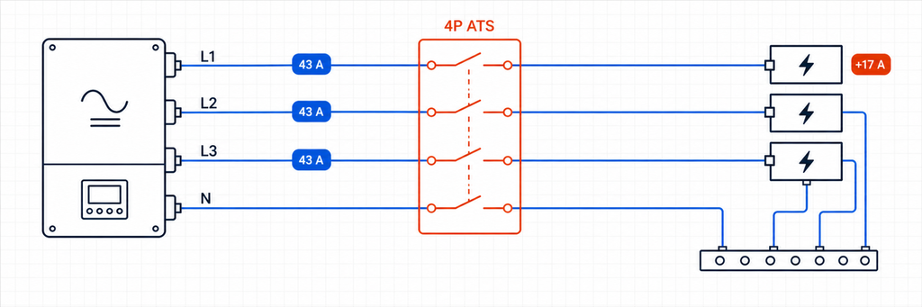
لا يثبت هذا النتيجة أن ATS بقدرة 50 A مناسب. تحقق مما إذا كان تصنيف مرور الشبكة 63 A، 80 A، أو قيمة أخرى؛ وما إذا كانت لوحة النسخ الاحتياطي يمكنها تركيز الأحمال أحادية الطور على طور واحد؛ وما إذا كان العاكس يمكنه تغذية جميع الأطوار الثلاثة أثناء تشغيل الجزيرة. يمثل حمل 4 kW مضاف إلى طور واحد حوالي 17.4 A عند 230 V رغم أن إجمالي kVA ثلاثي الطور لا يزال مقبولًا.
قم بإعداد جدول توزيع المراحل للأحمال الأساسية. حافظ على توزيع الأحمال الأحادية الطور الكبيرة حيثما أمكن، وتحقق من أسوأ مرحلة بدلاً من المتوسط فقط. إذا سمح العاكس بتيار 40 A على كل مرحلة ولكن تجاوز الشبكة يسمح بتيار 63 A، فقد يتطلب مفتاح التحويل التلقائي (ATS) عند حدود مخرج النسخ الاحتياطي/تجاوز الشبكة تصنيف تيار 63 A. يجب على ضوابط الأحمال في وضع النسخ الاحتياطي منع أي مرحلة من تجاوز حد العاكس.
تأكد أيضًا مما يحدث عند فشل إحدى المراحل. بعض وحدات تحكم ATS تقوم بالتحويل عند فقدان مرحلة؛ بعض العواكس الهجينة تفصل المخرج بالكامل؛ وبعض التطبيقات تتطلب تأخيرًا محددًا لمنع التشغيل على طاقة المرافق غير المستقرة. قد يكون من الضروري مراقبة تسلسل المراحل للمحركات والمعدات الدوارة. يجب أن تحدد مواصفات وحدة التحكم سلوك انخفاض الجهد، وارتفاع الجهد، وفقدان المرحلة، وتسلسل المراحل، والتردد — وليس فقط "تلقائي".
إضافة مولد إلى نظام شمسي هجين
يخلق المولد مصدرًا ثالثًا على الرغم من أن ATS التقليدي يختار عادة مصدرين فقط. لذلك يحتاج التصميم إلى تسلسل هرمي واضح. تشمل البنى الشائعة:
- المرافق مقابل المولد عند مدخل التيار المتردد للعاكس. يتلقى العاكس/الشاحن أي مصدر تيار متردد خارجي يختاره ATS المدخل، بينما يدير التتابع الداخلي الخاص به المرور والتشغيل بالبطارية.
- المرافق على مدخل شبكة العاكس والمولد على مدخل مخصص للمولد. تدير وحدة التحكم الهجينة كلا المصدرين دون ATS اختيار مصدر إضافي، بشرط أن يدعم النموذج هذا الترتيب.
- مخرج النسخ الاحتياطي للعاكس مقابل تجاوز المولد عند لوحة الأحمال الأساسية. يمكن أن يحافظ هذا على الأحمال إذا أصبح العاكس أو البطارية غير متاحين، ولكن يجب ألا يتم توصيل فرع المولد ومخرج العاكس بالتوازي عن غير قصد.
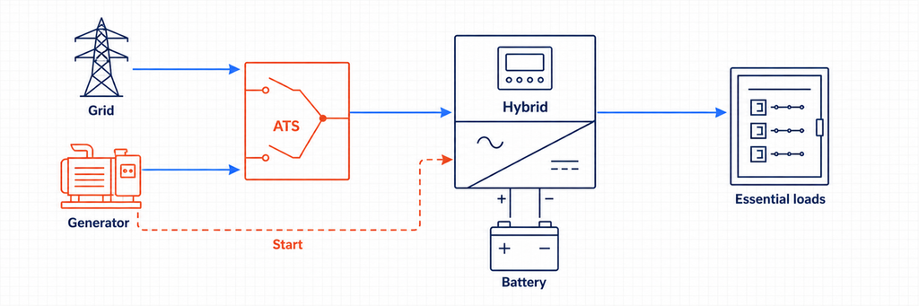
لحساب تيار المولد في ATS جانب المدخل للمرافق/المولد، احسب تيار المولد من تصنيفه بالكيلو فولت أمبير وقارنه بأقصى تيار مدخل تيار متردد مقبول للعاكس. افترض أن مولدًا أحادي الطور بقدرة 15 kVA و230 V يغذي عاكس شاحن. تياره الاسمي حوالي 65.2 A. إذا كان العاكس يقبل فقط 50 A، فقد تحد إعداداته أو الحماية العليا من تيار الشحن والمرور، لكن دائرة مصدر ATS لا تزال بحاجة إلى التنسيق مع قاطع المولد، والموصلات، ومسار الحمل الفعلي. لا تفترض أن حد الإدخال البرمجي بديل عن حماية الدائرة.
تشغيل المولد يضيف متطلبات تحكم لا تظهرها مخططات الطاقة الشمسية فقط: إشارة بدء، محاولات تشغيل، تأخير التسخين، التحقق من توفر المصدر، الحد الأدنى لوقت التشغيل، التبريد، جدول التمرين، تغذية راجعة للوقود المنخفض أو الأعطال، وعوامل حالة شحن البطارية. يمكن لـ ATS بسيط قائم على استشعار الجهد تحويل الأحمال، لكنه قد لا ينسق طاقة الشحن أو يمنع شاحن العاكس من تحميل مولد صغير. حيث يدير العاكس الهجين المولد، استخدم جهات الاتصال الجافة المحددة وتسلسل التحكم. إذا بدأ المولد ولكن لم يتم تحويل الحمل، اتبع تسلسل تشخيص تحويل المولد في ATS لتحديد أول حالة مفقودة لوحدة التحكم أو مسار الطاقة.
قد تتطلب أنظمة المصادر الثلاثة مرحلتين تحويل متداخلتين أو معدات تبديل متعددة المصادر مصممة خصيصًا. تشير IEC 60947-6-1:2026 إلى الحدود حول TSE متعدد المصادر والهجين ضمن وصف نطاقها، لذا يجب التحقق من التجميع الكامل وترتيب وحدة التحكم بدلاً من تجميع مفاتيح غير مرتبطة وافتراض الامتثال.
الشبكة المتصلة مقابل الشبكة المنفصلة: ما التغييرات في تسلسل التحويل؟
تسلسل النسخ الاحتياطي الهجين المتصل بالشبكة
في التشغيل العادي، تحدد المرافق مرجع الشبكة وقد تزود الأحمال عبر مسار المرور للعاكس. عندما يخرج جهد الشبكة أو التردد من النافذة المسموح بها، يفتح جهاز العزل المعتمد اتصال المرافق. فقط بعد تأكيد العزل يمكن للعاكس المشكل للشبكة تنشيط ناقل النسخ الاحتياطي. عندما تعود المرافق وتظل مستقرة خلال التأخير المكون، يعيد النظام التزامن أو ينفذ انتقالًا مفتوحًا وفقًا لمنطق التحكم المعتمد.
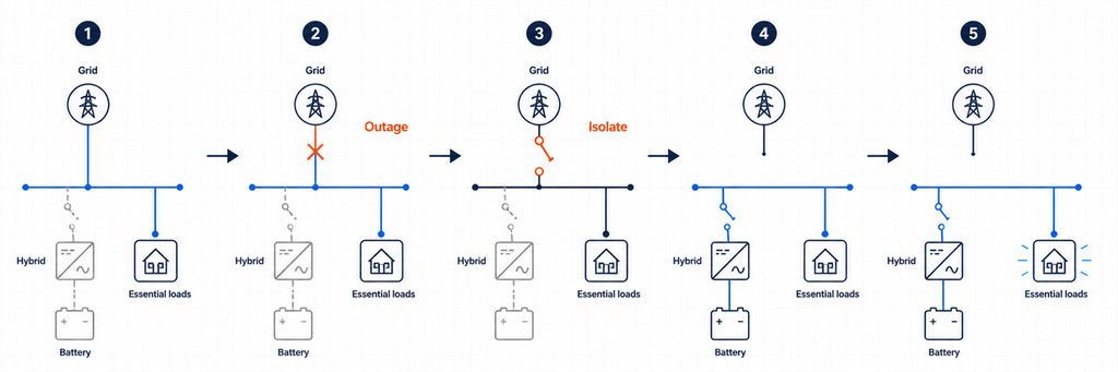
قد لا يعرف ATS عام يكتفي بالكشف عن "عدم وجود جهد" ما إذا كان العاكس قد أكمل العزل، أو ما إذا كان ناقل النسخ الاحتياطي مستقرًا، أو ما إذا كان إعادة الاتصال مسموحًا به. لهذا السبب تعتمد الأنظمة الهجينة غالبًا على وحدة تحكم مدمجة، واجهة نسخ احتياطي مخصصة، أو تنسيق جهات اتصال جافة محددة من مصنع العاكس.
تسلسل اختيار المصدر في الشبكة المنفصلة
في تركيب خارج الشبكة، يكون العاكس عادةً مصدر تشكيل الشبكة. يصبح مدخل المرافق البديلة أو المولد مقبولًا فقط بعد استقرار جهده وتردده. قد يختار ATS جانب المدخل بين المرافق والمولد قبل تغذية العاكس/الشاحن. ثم يقرر التتابع الداخلي للعاكس ما إذا كان سيمرر المصدر المقبول أو يستمر في دعم الأحمال من طاقة البطارية.
إذا وفر ATS جانب المخرج الثاني تجاوز صيانة، يجب تنسيق منطق تشغيله مع العاكس. يجب أن يمنع التصميم توصيل مصدر تجاوز إلى مخرج عاكس نشط ما لم يكن الجهاز مخصصًا خصيصًا للتشغيل المتوازي المتزامن. لا يجب أن تعتمد الأقفال الميكانيكية والكهربائية على أوامر البرامج فقط.
الأقطاب، تبديل النيوترال، والتأريض
لا تختار 2P أو 3P أو 4P فقط بناءً على قاعدة بسيطة "طور واحد مقابل ثلاثة أطوار". حدد ما إذا كان يجب أن يبقى النيوترال متصلًا بإحكام أو يتم تبديله، وكيف يتم تأريض كل مصدر، وأين يوجد الربط بين النيوترال والأرض، وكيف يتصرف الحماية من التيار المتبقي في كل حالة مصدر.
قد يستخدم نظام خط ونيوترال أحادي الطور ترتيب تحويل ذو قطبين حيث يجب تبديل كلا الموصلين. قد يتطلب نظام ثلاثي الطور بأربعة أسلاك ATS بأربعة أقطاب عندما ينشئ المصدر البديل نيوترالًا مشتقًا بشكل منفصل أو مرجعًا مختلفًا. تحتفظ أنظمة أخرى عمدًا بنيوترال مشترك. يعتمد الترتيب الصحيح على تصميم العاكس، والقوانين المحلية، ومتطلبات المرافق، والمخطط المعتمد من الشركة المصنعة.
يمكن أن يؤدي التعامل غير الصحيح مع النيوترال إلى إنشاء مسارات نيوترال متوازية، تيار دوار، حماية غير فعالة من التيار المتبقي، انقطاعات مزعجة، أو نظام نسخ احتياطي عائم. قم بإعداد جدول حالة النيوترال والأرض لوضع المرافق، وضع الجزيرة، وضع المولد، وتجاوز الصيانة. إذا لم يظهر الجدول استراتيجية ربط مقصودة واحدة في كل حالة، فالتصميم غير جاهز للتركيب.
قدرة تحمل تيار القصر ليست هي تيار التشغيل المستمر
لدى الأنظمة الهجينة مصدران مختلفان جدًا لتيار الخطأ. يمكن للمرافق توفير تيار قصر مرتفع متوقع. عادةً ما يحد العاكس الإخراج إلكترونيًا وقد يوفر فقط مضاعفًا معتدلاً للتيار المقنن لفترة قصيرة. لا يزال على ATS أن يتحمل، وعند الحاجة، يغلق على أسوأ عبء قصر متاح في نقطة تركيبه.
تحقق من تيار الخطأ المتاح من كل مصدر متصل، وجهاز الحماية العلوي، وبيانات تحمل القصر أو الإغلاق المشروطة من مصنع ATS. لا تفترض أن تيار الخطأ المحدود للعاكس يجعل مفتاح التحويل الصغير مقبولًا إذا كانت نفس جهات الاتصال متصلة بتجاوز شبكة قوية.
للمشاريع الموجهة بمعايير IEC, IEC 60947-6-1:2026 يغطي معدات تبديل التحويل المستخدمة لنقل الحمل بين المصادر. بالنسبة للمشاريع في أمريكا الشمالية, نظرة عامة على شهادات مفاتيح UL تحدد فئات UL 1008 لمفاتيح التحويل التلقائي وغير التلقائي. طبق دائمًا النسخة وقواعد التركيب المعتمدة من سلطة المشروع المختصة.
زمن النقل: لا يُعتبر ATS تلقائيًا UPS
يشمل نقل ATS الكشف، التحقق، التشغيل الميكانيكي، وزمن الاستقرار. حتى التبديل السريع قد يسبب انقطاعًا كافيًا لإعادة ضبط وحدات التحكم، الكونتاكتورات، معدات الاتصالات، أو الحواسيب. قد يدعم العاكس الهجين المزود بمرحّل نقل داخلي انتقالًا أقصر من ATS الكهروميكانيكي المنفصل، لكن القيمة الفعلية يجب أن تستند إلى وثائق النظام والاختبارات.
صنف الأحمال حسب تحملها للانقطاع المؤقت. قد تتحمل الإضاءة والتبريد انقطاعًا قصيرًا. قد تتطلب الخوادم، PLC، المعدات الطبية، وأجهزة الشبكة UPS أو مسار عاكس بدون انقطاع. لا تعد بـ "طاقة مستمرة" بناءً على تصنيف التيار الخاص بـ ATS.
تفاصيل التحكم والاستشعار التي تحدد ما إذا كان يعمل
- استشعار المصدر: قِس الجهد والتردد عند أطراف المصدر الفعلية. إنتاج PV أو حالة شحن البطارية ليست هي نفسها مصدر AC احتياطي سليم.
- تأخيرات النقل: منع التبديل السريع أثناء ظروف المرافق غير المستقرة والسماح لمولد أو حافلة العاكس بالاستقرار.
- المصدر المفضل: حدد ما إذا كان خرج العاكس الاحتياطي، تجاوز الشبكة، أو المولد هو المصدر الطبيعي لكل ATS.
- الملامسات الجافة: أكد تصنيفات الملامسات الخالية من الجهد، قطبية المنطق، وسلوك الفشل الآمن قبل توصيل ضوابط العاكس أو المولد.
- منطق العودة: حدد ما إذا كان النظام يعود تلقائيًا إلى المرافق، ينتظر استعادة البطارية، أو يتطلب موافقة يدوية.
- وضع الفشل: قرر ما يحدث إذا فشل متحكم العاكس، محرك ATS، فتيل الاستشعار، أو رابط الاتصالات.
للمشاريع التي تحتاج إلى حالة عن بُعد، اختر مفتاح نقل تلقائي بالاتصالات المساعدة المطلوبة أو خيارات الاتصالات. حافظ على قفل المصدر السلكي مستقلاً عن المراقبة الإشرافية.
كيفية قراءة بيانات العاكس وATS معًا
تستخدم كتيبات العاكس وبيانات ATS مصطلحات مختلفة، لذا أنشئ مقارنة متقاطعة بدلاً من مقارنة سطر "التيار المقنن" فقط.
| بيانات العاكس | بيانات ATS للمقارنة | سؤال التصميم |
|---|---|---|
| أقصى تيار احتياطي مستمر | التيار التشغيلي المقنن وفئة الاستخدام | هل يمكن للملامسات حمل خرج العاكس بشكل مستمر؟ |
| أقصى تيار دخل/مرور AC | التيار التشغيلي المقنن وسعة الطرف | هل يمكن لـ ATS حمل مسار الشبكة أو المولد الأكبر؟ |
| منحنى حمل الخرج الزائد | واجب القطع/الربط وفئة الحمل | هل ستسبب أحداث المحرك أو المحول إجهاد النقل أو إيقاف تشغيل العاكس؟ |
| نوافذ جهد/تردد الشبكة والاحتياطي | نطاق استشعار المتحكم والعتبات القابلة للتعديل | هل يتفق الجهازان على أن المصدر مقبول؟ |
| زمن النقل الداخلي | زمن تشغيل وتأخير مقصود لـ ATS | ما الانقطاع الذي ستختبره الحمولة فعليًا؟ |
| مخطط النيوترال/التأريض | ترتيب التبديل 2P أو 3P أو 4P | هل يحافظ كل وضع تشغيل على نظام الربط المعتمد؟ |
| أقصى تيار مساهمة في الخطأ | تصنيف تحمل القصر/التصنيف الشرطي | هل المفتاح منسق لكل من مصادر العاكس والمرفق؟ |
| واجهة تلامس جاف أو اتصالات | مدخلات ومخرجات وحدة التحكم والتلامسات المساعدة | هل يمكن للأجهزة تبادل الإشارات المسموح بها، وحالة الخطأ، وحالة الموضع بأمان؟ |
إذا كانت قيمة مفقودة، يُرجى طلبها قبل إصدار مواصفة المفتاح. "متوافق مع الطاقة الشمسية" ليست تصنيفًا كهربائيًا. وبالمثل، "ATS بقدرة 63 A" لا يوضح ما إذا كان الجهاز مناسبًا للجهد، فئة الحمل، مستوى الخطأ، تسلسل التبديل، أو شهادة السوق.
أخطاء شائعة في تحديد حجم ATS للعاكس الهجين المشترك
التحديد بناءً على قدرة مصفوفة الطاقة الشمسية (PV) بالكيلوواط
مصفوفة بقدرة 12 kWp لا تعني أن ATS يحمل 12 kW. تصنيف التيار المتردد للعاكس، حد تفريغ البطارية، مسار مرور الشبكة، وطلب الحمل المنقول تحدد التيار في مواقع مختلفة.
استخدام تصنيف خرج العاكس فقط
قد تمر الشبكة أو المولد تيارًا أكبر عبر ATS مما يمكن للعاكس إنتاجه. هذا هو السبب الأهم لتسجيل تصنيفات المرور والتجاوز بشكل منفصل.
تكرار وظيفة النقل الداخلي
يمكن لوحدتي تحكم أوتوماتيكية إصدار أوامر متناقضة، أو خلق انقطاعات غير ضرورية، أو تجاوز تسلسل العزل المعتمد للعاكس. استخدم علاقة تحكم رئيسية موثقة.
افتراض أن أي عاكس متصل بالشبكة يمكنه توفير النسخ الاحتياطي
توضح وزارة الطاقة الأمريكية أن العواكس المتبعة للشبكة (grid-following) تغلق عند انقطاع التيار الشبكي، بينما تتطلب القدرة على تشكيل الشبكة (grid-forming) للعمل خارج الشبكة أو كنسخ احتياطي. ATS وحده لا يوفر هذه القدرة.
تجاهل سلوك النيوترال
يمكن أن يكون تصنيف التيار صحيحًا بينما يظل النظام غير آمن بسبب ترتيب خاطئ للنيوترال أو الربط. راجع عمل الموصل الحامي والتيار المتبقي في كل حالة نقل.
معاملة ATS كحماية من التيار الزائد
مفتاح النقل يغير مسارات المصدر. ما لم يكن المنتج المختار ترتيب حماية من نوع CB، لا تزال هناك حاجة إلى قواطع أو صمامات منسقة.
اختبارات التشغيل قبل تشغيل النظام
- تحقق من هوية الموصل، عزم ربط الأطراف، تسلسل الطور، القطبية، استمرارية النيوترال، واتصالات التأريض الوقائي.
- أكد أن أسماء مصادر ATS تطابق المصادر المفضلة والبديلة الفعلية.
- قِس جهد وتردد الشبكة، النسخ الاحتياطي للعاكس، والمولد عند نقاط الاستشعار.
- حاكي فشل الشبكة وتأكد من حدوث عزل المرفق قبل تنشيط حافلة الجزيرة.
- طبق أحمال أساسية ممثلة وتحقق من بقاء التيار الاحتياطي ضمن حد العاكس.
- عطل أو أوقف العاكس وتحقق من استجابة التجاوز المقصودة دون تغذية عكسية لمخرجه.
- أعد تشغيل المرفق وتأكد من تأخير إعادة النقل، وفحوصات استقرار المصدر، وحالة التشغيل النهائية.
- اختبار حالات انخفاض البطارية، الحمل الزائد، التوقف الطارئ، التشغيل اليدوي، وفقدان الاتصالات.
- تسجيل أوقات النقل، التيارات، الإنذارات، إعدادات وحدة التحكم، وتغييرات الأسلاك كما تم تنفيذها.
يجب أن يتم التكليف بواسطة فنيين مؤهلين باستخدام إجراء اختبار معتمد. يمكن لأنظمة الطاقة الشمسية والبطاريات المتصلة بالمرافق أن تغذي الموصلات من عدة اتجاهات حتى عندما يكون أحد مفاتيح الفصل مفتوحًا.
قائمة التحقق لمواصفات ATS لمشروع هجين للطاقة الشمسية
| بند المواصفة | إدخال المشروع |
|---|---|
| وظيفة وموقع ATS | محدد مصدر الإدخال، تجاوز خرج النسخ الاحتياطي، أو عزل الخدمة |
| المصدر الأول / المصدر الثاني | المرفق، المولد، خرج النسخ الاحتياطي للعاكس، أو تركيبة معتمدة |
| تيار الحمل المنقول التصميمي | من جدول الأحمال والقواعد المحلية |
| تيار النسخ الاحتياطي للعاكس | القيمة المستمرة القصوى من الشركة المصنعة |
| تيار مرور/تجاوز الشبكة | الحد الأقصى المسموح به في نقطة التركيب |
| التيار التشغيلي المقنن | يتم اختياره بعد فحص الحمل، التخفيض، والتنسيق |
| الجهد، التردد، الأطوار | مطابقة كلا المصدرين والحمل |
| الأقطاب والمحايد | بناءً على تصميم التأريض المعتمد |
| بيانات تيار الخطأ | تيار الخطأ المتاح وجهاز الحماية المنسق |
| طريقة النقل | انتقال مفتوح ما لم يُطلب طريقة متزامنة معتمدة |
| التحكم والتغذية الراجعة | عتبات الاستشعار، التأخيرات، الاتصالات الجافة، الحالة، الاتصالات |
| دليل التوافق | مخطط خط واحد معتمد من العاكس والشهادات المعمول بها |
قاعدة الاختيار النهائية
الحجم الصحيح لـ ATS لعاكس شمسي هجين هو التصنيف المطلوب عند الحدود الكهربائية الحقيقية للمفتاح - وليس الرقم المطبوعة بجانب مجموعة PV. أولاً، إثبات أن النظام لديه طريقة معتمدة لتشكيل الشبكة والعزل. ثم قارن تيار الحمل المنقول، تيار خرج النسخ الاحتياطي للعاكس، وتيار مرور أو تجاوز الشبكة. اختر التيار الأعلى الموثوق به عبر ذلك الموقع وأكمل التصميم بفحص الأقطاب، المحايد، تيار الخطأ، وقت النقل، الحماية، ووحدة التحكم.
للاختيار الخاص بالمشروع، أرسل إلى JUTRION مخطط الخط الواحد، جهد النظام والأطوار، نموذج العاكس، تيار خرج النسخ الاحتياطي، تصنيف المرور، جدول الحمل المنقول، تيار الخطأ المتاح، والإشارات التحكم المطلوبة. تتيح هذه التفاصيل تكوين ATS للتوافق مع الهندسة الفعلية الهجينة أو خارج الشبكة.
الأسئلة الشائعة
هل أحتاج إلى ATS مع عاكس شمسي هجين؟
ليس دائماً. العديد من العواكس الهجينة تحتوي بالفعل على مرحل تحويل داخلي أو تعمل مع واجهة احتياطية مخصصة. يكون استخدام ATS خارجي مناسبًا فقط عندما تتطلب هندسة الشركة المصنعة المعتمدة وظائف مثل اختيار الإدخال بين الشبكة والمولد، تجاوز خرج العاكس، أو التكرار للصيانة. إضافة ATS آخر دون التحقق من المخطط المعتمد قد يسبب تعارضًا في منطق التحويل.
هل يمكن لـ ATS تشغيل عاكس شمسي متصل بالشبكة أثناء انقطاع التيار؟
لا. العاكس التقليدي المتبع للشبكة ينفصل عند عدم توفر شبكة المرافق. لا يمكن لـ ATS منحه قدرة تشكيل الشبكة. يتطلب التشغيل الاحتياطي معدات جزيرة متوافقة، عاكس مصمم لإنشاء حافلة AC محلية، وعادةً تخزين بطاريات أو مصدر طاقة مستقر آخر.
هل يجب أن يتطابق حجم ATS مع تصنيف العاكس الشمسي بالكيلوواط؟
ليس بالضرورة. يجب أن يكون تصنيف ATS مناسبًا لأقصى تيار يمكن أن يمر عبر موقع تركيبه. قد يوفر العاكس الهجين 35 A في وضع النسخ الاحتياطي بينما يسمح بمرور تيار 63 A من الشبكة. إذا كان ATS يحمل مسار الشبكة هذا، فإن التيار الأكبر المعقول — وليس فقط قدرة مصفوفة PV أو كيلوواط العاكس — هو الذي يحدد فئة التيار الأولية.
كيف أحول kVA العاكس الهجين إلى تيار ATS؟
لأنظمة الطور الواحد، اقسم القدرة الظاهرة بالـ VA على الجهد: I = S ÷ V. للأنظمة الثلاثية الأطوار المتوازنة، استخدم I = S ÷ (√3 × V). قارن النتيجة مع الحد الأقصى المعلن للتيار AC للعاكس، لأن حد اللوحة التعريفية له الأولوية على الحساب المثالي. ثم تحقق مما إذا كان تيار مرور الشبكة أو طلب الحمل المنقول أعلى.
هل يجب تركيب ATS قبل العاكس الهجين أم بعده؟
يعتمد ذلك على الوظيفة المقصودة. قد يختار ATS على جانب الإدخال بين المرافق أو المولد قبل العاكس/الشاحن. قد يختار ATS على جانب الإخراج خرج النسخ الاحتياطي للعاكس أو تجاوز مباشر للشبكة للوحة الأحمال الأساسية. قد يكون جهاز تحويل حدود الخدمة جزءًا من واجهة احتياطية مخصصة. هذه المواقع لها متطلبات مختلفة للتيار، والنيترال، والاستشعار، والتحكم.
هل أحتاج إلى ATS ذو قطبين أم أربعة أقطاب لعاكس شمسي؟
اختر ترتيب الأقطاب بناءً على عدد الأطوار وتصميم النيترال والتأريض المعتمد. بعض الأنظمة تحتفظ بنيترال صلب؛ والبعض الآخر يجب أن يبدل النيترال لتجنب المسارات المتوازية أو لاستيعاب مصدر مشتق منفصل. لا تطبق قاعدة عامة "طور واحد يساوي 2P" أو "ثلاثة أطوار يساوي 4P" دون التحقق من دليل العاكس، الكود المحلي، حماية التيار المتبقي، وترتيب الربط.
هل يمكنني استخدام ATS أكبر من تيار خرج العاكس؟
نعم، بشرط أن تكون الجهد، والأقطاب، ودرجة الاستخدام، وتصنيف العطل، والحماية، والتحكم، والشهادة مناسبة. غالبًا ما يكون ATS الأكبر مطلوبًا عندما يتجاوز تيار تجاوز الشبكة تيار النسخ الاحتياطي للعاكس. ومع ذلك، لا يزيد المفتاح الأكبر من خرج العاكس أو سعة البطارية؛ يجب أن تظل الأحمال الاحتياطية ضمن حد العاكس.
هل ATS سريع بما يكفي ليحل محل UPS؟
ليس بالضرورة. قد يسبب اكتشاف المصدر، والتحقق، والتشغيل الميكانيكي، واستقرار العاكس انقطاعًا. قد تحتاج الحواسيب الحساسة، والخوادم، وأجهزة التحكم، ومعدات الاتصالات، أو الأحمال الطبية إلى UPS أو مسار طاقة بدون انقطاع معتمد. تحقق من وقت التحويل الكامل للنظام بدلاً من الاعتماد على تصنيف تيار ATS فقط.
المراجع
