

วิธีเลือก ATS 2P, 3P หรือ 4P สำหรับระบบเฟสเดียวและสามเฟส
คำตอบด่วน
2P สลับตัวนำที่นำกระแสไฟฟ้าสองตัว. 3P โดยปกติจะสลับ L1, L2 และ L3. 4P สลับ L1, L2, L3 และ N การเลือกขั้นสุดท้ายขึ้นอยู่กับแหล่งจ่าย นิวทรัล การต่อลงดิน และการออกแบบการป้องกัน.
ATS แบบสองขั้วและ ATS แบบสี่ขั้วไม่ใช่เวอร์ชันเริ่มต้นและเวอร์ชันพรีเมียมของคำตอบเดียวกัน สิ่งเหล่านี้อาจเป็นตัวเลือกที่ถูกต้องสำหรับระบบไฟฟ้าที่แตกต่างกัน การเปรียบเทียบที่มีประโยชน์คือตัวนำใดที่แต่ละสวิตช์ถ่ายโอน โดยเฉพาะนิวทรัล.
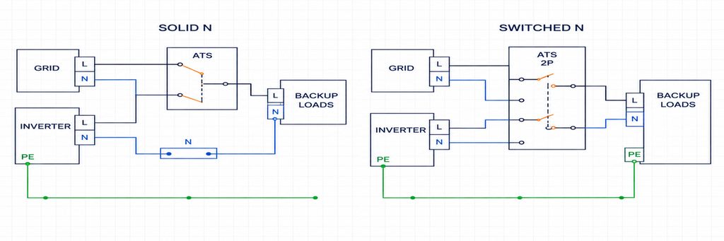
สำหรับแหล่งจ่ายแบบเฟสเดียวแบบไลน์และนิวทรัล ให้เลือก 2P ATS ที่เหมาะสมเมื่อทั้ง L และ N ต้องถูกถ่ายโอน สำหรับแหล่งจ่ายสามเฟส ให้เลือก 3P เมื่อมีเพียงตัวนำไลน์สามตัวที่ถูกถ่ายโอน หรือ 4P เมื่อนิวทรัลต้องถูกถ่ายโอนด้วย. การตัดสินใจเกี่ยวกับนิวทรัลมาจากการเชื่อมโยงแหล่งจ่าย การจัดวางการต่อลงดิน และข้อกำหนดในการติดตั้ง—ไม่ใช่เพียงแค่ว่าแหล่งจ่ายสำรองเป็นเครื่องกำเนิดไฟฟ้าหรืออินเวอร์เตอร์ ระบบ 120/240 V แบบแยกเฟสต้องการความสนใจแยกต่างหาก: สวิตช์ 2P ที่เหมาะสมสามารถถ่ายโอนตัวนำร้อนสองตัวได้ในขณะที่รักษานิวทรัลแบบต่อเนื่อง.
สำหรับผู้จัดจำหน่ายและผู้สร้างตู้ควบคุม การระบุฟังก์ชันตัวนำเหล่านี้พร้อมกับจำนวนขั้วจะป้องกันความคลาดเคลื่อนในการเสนอราคาที่พบบ่อย: ซัพพลายเออร์สองรายเสนออุปกรณ์ “2P” ที่มีจุดประสงค์สำหรับการจัดวางแหล่งจ่ายที่แตกต่างกัน.
เปรียบเทียบ ATS แบบ 2P, 3P และ 4P ตามฟังก์ชันตัวนำ
ขั้วคือเส้นทางตัวนำไฟฟ้าที่ถูกสลับ ไม่ใช่แหล่งจ่ายไฟ ไม่ใช่เฟสตามนิยาม หรือตำแหน่งสวิตช์ ATS แบบสองแหล่งจ่ายถ่ายโอนโหลดระหว่างแหล่งจ่ายสองแหล่งไม่ว่าจะมีสอง สาม หรือสี่ขั้ว ในทำนองเดียวกัน กลไก I–0–II มีสามตำแหน่งการทำงาน ซึ่งไม่ได้ทำให้เป็นอุปกรณ์สามขั้ว.
การเปรียบเทียบต่อไปนี้สมมติว่าเป็นการใช้งานถ่ายโอน AC การต่อลงดินเพื่อป้องกันอยู่นอกการจัดวางหน้าสัมผัสการถ่ายโอนแหล่งจ่ายปกติ.
| การจัดวางแหล่งจ่ายและนิวทรัล | ตัวนำที่ถูกถ่ายโอน | การกำหนดค่า ATS ที่ต้องตรวจสอบ | การตรวจสอบชี้ขาด |
|---|---|---|---|
| เฟสเดียว L–N โดยต้องสลับนิวทรัล | L และ N | 2P ที่ได้รับการรับรองสำหรับการสลับไลน์และนิวทรัล | การอ้างอิงนิวทรัลบนแหล่งจ่ายที่เลือกและลำดับหน้าสัมผัส |
| โหลดสามเฟสที่ไม่มีนิวทรัลแบบกระจาย | L1, L2 และ L3 | 3P | โหลดและตัวควบคุมทำงานได้จริงโดยไม่มี N แบบกระจาย |
| ระบบสามเฟสสี่สายที่มีนิวทรัลร่วมที่ได้รับการรับรอง | L1, L2 และ L3; N ยังคงเชื่อมต่ออยู่ | 3P ที่มีการจัดเตรียมนิวทรัลแบบต่อเนื่องที่เหมาะสม | ตำแหน่งการเชื่อมโยงและเส้นทางกระแสฟอลต์ในโหมดแหล่งจ่ายทั้งสอง |
| ระบบสามเฟสสี่สายที่ต้องการการแยกนิวทรัลของแหล่งจ่าย | L1, L2, L3 และ N | 4P ที่มีการจัดวางหน้าสัมผัสนิวทรัลที่ต้องการ | หน้าที่การสลับนิวทรัล จังหวะเวลา และการต่อลงดินของแหล่งจ่ายที่เลือก |
| 120/240 V แบบแยกเฟสที่มีนิวทรัลแบบต่อเนื่อง | L1 และ L2; N ยังคงเชื่อมต่ออยู่ | 2P ที่ได้รับการจัดอันดับและกำหนดค่าเฉพาะสำหรับแบบแยกเฟส | การตรวจจับแรงดันไฟฟ้า แหล่งจ่ายควบคุม และการออกแบบการเชื่อมโยงที่ได้รับการรับรอง |
| 120/240 V แบบแยกเฟสที่มีการสลับนิวทรัล | L1, L2 และ N | เส้นทางที่ถูกสลับสามเส้นทางในการประกอบแบบแยกเฟสที่ได้รับการรับรอง | แผนภาพผู้ผลิต แทนที่จะเป็นสมมติฐานขั้วสามเฟสทั่วไป |
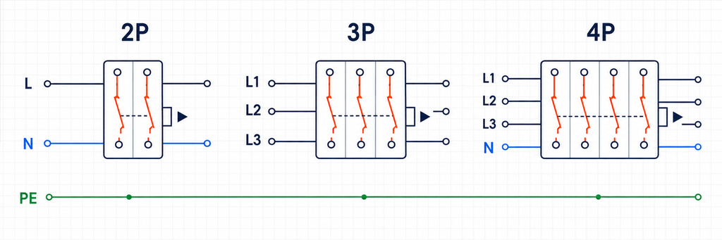
แผนภาพขั้วเป็นกุญแจสำคัญของตารางนี้: แยกแยะหน้าสัมผัสกระแสโหลดจากขั้วใดๆ ที่ใช้เพียงสำหรับการตรวจจับหรือควบคุม หลักการทำงานของ ATS และคู่มือการเลือกเบื้องต้น อธิบายกลไกการถ่ายโอนพื้นฐาน.
การเลือก ATS เฟสเดียว: ขั้วที่สองสลับอะไร?
แหล่งจ่ายแบบไลน์และนิวทรัล
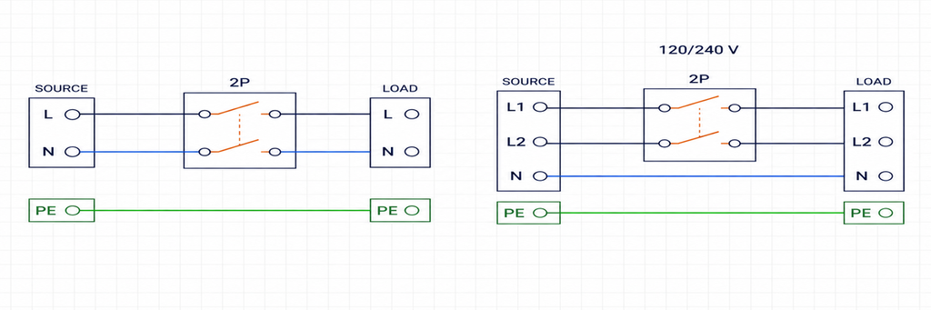
ในการใช้งาน 230 V แบบไลน์ถึงนิวทรัลทั่วไป โหลดจะได้รับตัวนำไลน์หนึ่งตัวและนิวทรัลหนึ่งตัว เมื่อการออกแบบการถ่ายโอนต้องการให้ทั้งสองตัดการเชื่อมต่อจากแหล่งจ่ายขาออก ATS แบบ 2P จะให้เส้นทางหนึ่งสำหรับ L และอีกเส้นทางสำหรับ N.
นี่เป็นจุดเริ่มต้นที่เป็นประโยชน์สำหรับตู้ควบคุมเชิงพาณิชย์ขนาดเล็กและโหลดที่จำเป็นจำนวนมาก ไม่ใช่กฎสากลที่ว่าทุกการติดตั้งเฟสเดียวต้องใช้การสลับนิวทรัล การติดตั้งบางแห่งรักษานิวทรัลร่วมภายใต้กฎการออกแบบที่ใช้บังคับ แบบDrawing ของโครงการต้องชี้ขาดความแตกต่างนั้นก่อนสั่งซื้ออุปกรณ์.
สำหรับการจัดวางแบบ L–N ที่สลับนิวทรัล ให้อ่านเครื่องหมายขั้วแหล่งจ่ายปกติ แหล่งจ่ายสำรอง และโหลดเป็นสามชุดที่เกี่ยวข้องกัน ขั้วนิวทรัลที่มีจุดประสงค์สำหรับการตรวจจับไม่จำเป็นต้องเป็นขั้วนิวทรัลโหลดที่ถูกสลับ ภาพถ่ายที่แสดงสองโมดูลก็ไม่ได้พิสูจน์ว่าตัวนำทั้งสองถูกถ่ายโอนระหว่างแหล่งจ่ายทั้งสอง.
แหล่งจ่ายแบบแยกเฟส
แหล่งจ่าย 120/240 V แบบแยกเฟสในอเมริกาเหนือโดยปกติมีตัวนำร้อนสองตัวและนิวทรัลหนึ่งตัว สวิตช์ถ่ายโอนที่ออกแบบสำหรับการทำงานแบบนิวทรัลต่อเนื่องสามารถใช้สองขั้วเพื่อถ่ายโอนตัวนำร้อนสองตัว โดยปล่อยให้นิวทรัลอยู่บนการเชื่อมต่อต่อเนื่องที่ได้รับการรับรอง.
สองขั้วไม่ได้หมายความโดยธรรมชาติว่ามีสายไฟร้อนหนึ่งเส้นบวกกับสายกลาง เช่นเดียวกัน ผลิตภัณฑ์ 230 V L–N ไม่สามารถสันนิษฐานว่าเหมาะสำหรับบริการ 120/240 V ได้เพียงเพราะมีสองขั้ว ตัวควบคุมการตรวจจับ ระดับฉนวน แหล่งจ่ายเสริม และการรับรองผลิตภัณฑ์ทั้งหมดต้องตรงกับการใช้งาน
ถ้าการออกแบบสปลิตเฟสต้องการการสวิตช์สายกลาง จำเป็นต้องมีเส้นทางสวิตช์ที่สาม นั่นไม่ได้อนุญาตให้เชื่อมต่อแหล่งสปลิตเฟสกับ ATS สามเฟสธรรมดา ตัวควบคุมอาจคาดหวังแรงดันสามเฟสหรือปฏิเสธแหล่งจ่ายเป็นสภาวะขาดเฟส ให้ระบุชุดประกอบที่ผู้ผลิตรองรับสำหรับระบบจริง
ทั้งสองการจัดเรียงไม่ได้แปลงแหล่งจ่ายเข้า ATS 2P ไม่สามารถเปลี่ยนแหล่ง 230 V เส้นถึงกลางเป็นแหล่งสปลิตเฟส 120/240 V ได้ แหล่งจ่ายสำรองต้องให้แรงดันและความสัมพันธ์ของสายที่โหลดเชื่อมต่อจำเป็น
การเลือก ATS สามเฟส: สายกลางไม่ได้หมายความอัตโนมัติว่าเป็น 4P
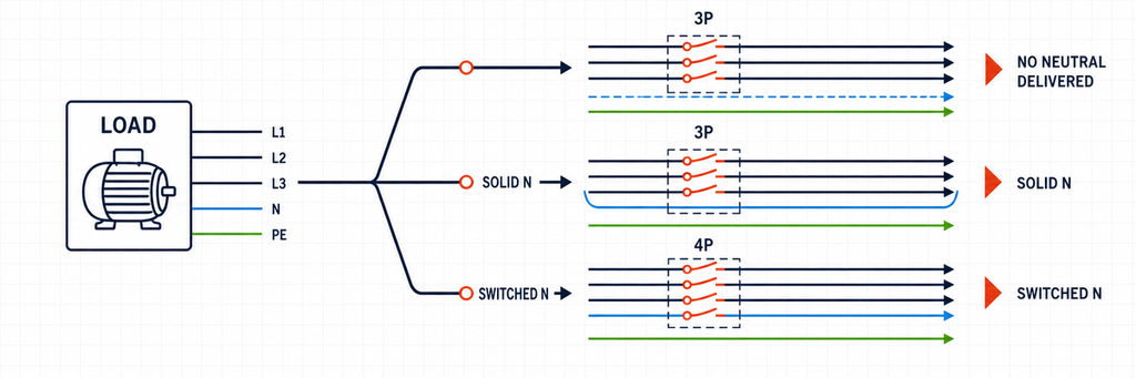
โหลดสามเฟสสามารถใช้สายไฟสามเส้นโดยไม่มีสายกลางกระจาย หรือสามารถเป็นส่วนหนึ่งของเครือข่ายสี่สายที่จ่ายวงจรเส้นถึงกลาง ทั้งสองการจัดเรียงสามารถใช้สวิตช์ถ่ายโอนสามขั้วได้แต่ด้วยเหตุผลที่แตกต่างกัน
ไม่มีการแจกจ่ายสายกลางไปยังโหลดที่ถ่ายโอน
สำหรับฟีดเดอร์มอเตอร์สามสายแท้จริง 3P จะถ่ายโอน L1, L2 และ L3 ไม่มีสายกลางโหลดสำหรับขั้วที่สี่ถ่ายโอน สายดินป้องกันยังคงเป็นการเชื่อมต่อป้องกันแยกต่างหาก
ตรวจสอบแผงทั้งหมด ไม่ใช่แค่โหลดมอเตอร์ที่ใหญ่ที่สุด วงจรควบคุม ฮีตเตอร์ เต้ารับ หรืออุปกรณ์ตรวจสอบอาจมีความต้องการสายถึงกลางที่คำอธิบายโหลดเริ่มต้นละไว้ ตัวควบคุม ATS อาจต้องการสายกลางสำหรับแหล่งจ่ายหรือการตรวจจับของตัวเอง แม้มอเตอร์จะไม่ต้องการก็ตาม
มีการแจกจ่ายสายกลาง แต่ยังคงต่อเนื่อง
ATS 3P สามารถให้บริการโหลดสามเฟสสี่สายที่การออกแบบอนุญาตให้มีสายกลางร่วมต่อเนื่อง สายไฟสามเส้นถ่ายโอน สายกลางถูกส่งผ่านการเชื่อมต่อแยกต่างหากที่มีค่ากระแสที่เหมาะสม
นี่ไม่ใช่การ “ลืมสวิตช์สายที่สี่” แต่มันคือโทโพโลยีสายกลางที่ตั้งใจ ความเหมาะสมขึ้นอยู่กับวิธีที่แหล่งจ่ายอ้างอิงกับดินและวิธีการทำงานของการป้องกันความผิดพลาด การเพิ่มเครื่องกำเนิดไฟฟ้าโดยไม่ตรวจสอบการเชื่อมต่อที่มีอยู่สามารถทำให้การจัดเรียงที่ยอมรับได้เป็นโมฆะ
ความแตกต่างนี้สำคัญโดยเฉพาะเมื่อการติดตั้งเปลี่ยนจากการกำหนดค่าเครื่องกำเนิดไฟฟ้าแบบหนึ่งไปยังอีกแบบหนึ่ง โครงการที่สามด้านล่างแสดงให้เห็นว่าแหล่งจ่ายใหม่สามารถเปลี่ยนการเลือกขั้วที่ถูกต้องโดยไม่เปลี่ยนโหลด
สายกลางของแหล่งจ่ายต้องถ่ายโอนพร้อมสายไฟ
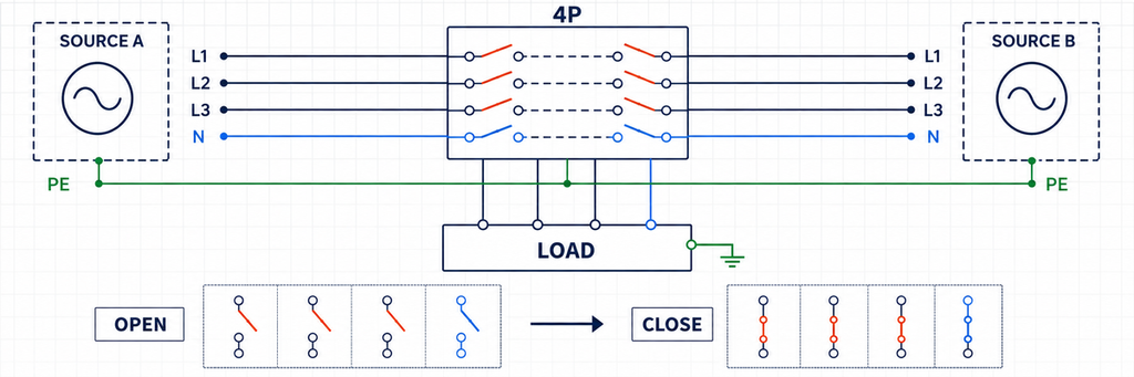
สำหรับการใช้งานสามเฟสสี่สายที่ต้องแยกสายกลางของแหล่งจ่าย ให้พิจารณา 4P เส้นทางสวิตช์ที่สี่ช่วยให้สายกลางโหลดตามแหล่งที่เลือกแทนที่จะเชื่อมต่อกับสายกลางของทั้งสองแหล่งอย่างต่อเนื่อง
คำว่า “แยกวงจร” ต้องระมัดระวังที่นี่ ATS ที่สวิตช์สายกลางไม่ได้ตัดการเชื่อมต่อระบบสายดินป้องกัน และจำนวนขั้วเพียงอย่างเดียวไม่พิสูจน์ความเหมาะสมเป็นสวิตช์แยกวงจรสำหรับงานบำรุงรักษา การเชื่อมต่ออื่น ๆ รวมถึงสายบายพาสก็ยังคงเกี่ยวข้อง ให้บรรยายฟังก์ชันจริงว่าเป็นการสวิตช์สายกลางของแหล่งจ่ายแทนการสัญญาว่าจะแยกไฟฟ้าทั้งหมดที่เชื่อมต่อกับไซต์อย่างสมบูรณ์
สามโครงการ สามการตัดสินใจขั้วที่แตกต่างกัน
ตัวอย่างต่อไปนี้เป็นบรีฟวิศวกรรมประกอบภาพ ไม่ใช่การติดตั้งลูกค้า JUTRION สมมติว่าความต้องการกระแสได้กำหนดไว้แยกต่างหาก แต่ละตัวอย่างแยกการตัดสินใจที่กำหนดสายที่สวิตช์
โครงการ 1: แผงโหลดสำคัญ 230 V — เลือก 2P สำหรับ L และ N
อาคารพาณิชย์ขนาดเล็กต้องการสำรองสำหรับแสงสว่าง การสื่อสาร และวงจรตู้เย็น แหล่งจ่ายทั้งสองให้แรงดัน 230 V เส้นถึงกลางที่ 50 Hz แผงโหลดสำคัญมีความต้องการออกแบบ 40 A ที่บันทึกไว้ ATS ที่เสนอเป็นรุ่น 63 A ที่เหมาะสมกับหน้าที่การทำงาน การออกแบบติดตั้งต้องการให้สายไฟและสายดินกลางของแผงถ่ายโอนระหว่างแหล่งจ่าย
การตัดสินใจขั้วคือ 2P ถ่ายโอน L และ N ข้อกำหนดการต่อลงดินด้านแหล่งจ่ายกำหนดการอ้างอิงที่เหมาะสมสำหรับแต่ละโหมดการทำงาน สายดินกลางโหลดจะไม่ถูกปล่อยให้เชื่อมต่อกับแหล่งที่ไม่ทำงานผ่านการเชื่อมต่อที่สอง
ประเด็นหลักในการใช้งานคือขอบเขตของแผงโหลดสำคัญ การย้ายสายไฟไปยังสำรองในขณะที่ปล่อยสายดินกลางไว้บนบาร์สายดินกลางของแผงหลักที่ไม่เกี่ยวข้องจะทำลายการแยกที่ตั้งใจไว้ สายไฟที่เกี่ยวข้องของวงจรถ่ายโอนแต่ละวงจรต้องเป็นส่วนหนึ่งของการจัดเรียงสำรองที่ออกแบบไว้เดียวกัน
สำหรับผู้สร้างแผง หมายความว่า ATS ขนาดกะทัดรัดและตู้โหลดสำคัญควรพิจารณาร่วมกัน งานนี้ไม่ใช่แค่ติดตั้งสวิตช์ข้างแถวเบรกเกอร์ที่มีอยู่ ต้องมีที่ว่างสำหรับสายไฟวงจรขาออก จุดต่อสายดินกลาง และอุปกรณ์ป้องกัน
ตัวเลข 63 A ไม่ได้กำหนดขั้ว และตัวอย่างนี้ไม่ได้กำหนดมาร์จิ้นขนาดสากล ความต้องการที่บันทึกไว้เล็กกว่าหรือใหญ่กว่าสามารถเปลี่ยนระดับกระแสได้โดยไม่เปลี่ยนการตัดสินใจถ่ายโอน L–N
โครงการ 2: แผงปั๊มสามสาย 400 V — เลือก 3P
แผงปั๊มรับแหล่งจ่ายสามเฟส 400 V 50 Hz จากยูทิลิตี้หรือเครื่องกำเนิดไฟฟ้า มอเตอร์ใช้พลังงานเส้นถึงเส้น หม้อแปลงควบคุมที่เชื่อมต่อข้ามสองเส้นในด้านที่ถ่ายโอนจ่ายวงจรควบคุมของแผง ไม่มีโหลดเส้นถึงนิวตรอนหรือนิวตรอนจ่ายกระจายรวมอยู่ด้วย ตัวควบคุม ATS ที่ระบุรองรับการจัดเรียงสามสาย
การตัดสินใจจำนวนขั้วเป็น 3P โดยโอนถ่าย L1, L2 และ L3 ไม่มีโหลดนิวตรอนที่จะกำหนดให้กับขั้วที่สี่ การจัดเรียงทุติยภูมิของหม้อแปลงควบคุมเป็นรายละเอียดการออกแบบแยกต่างหาก; ไม่ได้สร้างความจำเป็นในการแจกจ่ายนิวตรอนของแหล่งจ่ายเข้ามา
ที่นี่การตรวจสอบเพิ่มเติมที่สำคัญคือลำดับเฟส การระบุขั้วออกต้องรักษาความสัมพันธ์เฟสที่ตั้งใจไว้ในแต่ละแหล่ง การถ่ายโอนทางกลที่สำเร็จไม่ใช่หลักฐานเพียงพอว่ามอเตอร์จะทำงานในทิศทางที่ตั้งใจไว้ ความเข้ากันได้ของแหล่งจ่ายและการว่าจ้างเป็นหน้าที่ของบุคลากรที่มีคุณสมบัติซึ่งใช้ขั้นตอนทดสอบที่ได้รับอนุมัติ
ซ็อกเก็ตบริการ 230 V ในอนาคตจะเปลี่ยนข้อกำหนดหากต้องการนิวตรอนจ่าย นักออกแบบสามารถจัดหาวงจรที่จ่ายแยกต่างหากหรือผ่านหม้อแปลงที่เหมาะสม หรือปรับเปลี่ยนการจัดเรียงการแจกจ่าย การสั่งซื้อ 4P ในวันนี้ไม่ได้หมายความว่าจะมีนิวตรอนที่ขาดหายไปหรือแก้ไขการออกแบบระบบกราวด์ในอนาคต
นี่คือขอบเขตต้นทุนที่มีประโยชน์: ซื้อฟังก์ชันที่แผงควบคุมครบถ้วนต้องการ ขั้วที่ไม่ได้ใช้ไม่สามารถแทนที่แหล่งจ่ายควบคุมที่ถูกต้อง หน้าที่สวิตช์มอเตอร์ หรือการตรวจสอบแหล่งจ่ายได้
โครงการที่ 3: แผงควบคุมเชิงพาณิชย์ 208/120 V — การเปลี่ยนแหล่งจ่ายสามารถเปลี่ยนตัวเลือกจาก 3P เป็น 4P
พิจารณาแผงควบคุมสามเฟสสี่สายแบบอเมริกาเหนือที่จ่ายทั้งอุปกรณ์แบบสายต่อสายและวงจร 120 V การออกแบบสำรองเดิมใช้สายกลางร่วมต่อเนื่อง โดยมีการอ้างอิงระบบที่บริการและไม่มีการเชื่อมนิวตรอนกับกรอบเครื่องกำเนิดไฟฟ้าในโครงสร้างที่ได้รับอนุมัตินี้ ATS 3P โอนถ่ายสายไฟร้อนสามสาย
เจ้าของตอนนี้เสนอการจัดเรียงเครื่องกำเนิดไฟฟ้าที่แตกต่างซึ่งรักษาการเชื่อมนิวตรอนกับกรอบของตนเองและจะทำงานเป็นแหล่งจ่ายแยกต่างหาก การเก็บการเชื่อมนิวตรอนร่วมเดิมจะเชื่อมต่อระบบนิวตรอนทั้งสองในขณะที่การเชื่อมต่อกราวด์ป้องกันยังเชื่อมต่ออุปกรณ์ กระแสนิวตรอนปกติอาจแบ่งออกเป็นเส้นทางขนานที่ไม่ได้ตั้งใจ
สำหรับการออกแบบที่แก้ไขซึ่งต้องแยกแหล่งจ่ายกับนิวตรอน ให้เลือกการจัดเรียง 4P ที่เหมาะสม เส้นทางนิวตรอนจะตามแหล่งจ่ายที่เลือก: อ้างอิงบริการในระหว่างการทำงานของยูทิลิตี้ อ้างอิงด้านเครื่องกำเนิดในระหว่างการทำงานสำรอง การต่อเนื่องของกราวด์ป้องกันจะถูกเก็บไว้แทนที่จะสวิตช์ออก
นักออกแบบโครงการต้องประสานการตรวจจับความผิดกราวด์และเส้นทางบายพาสใด ๆ กับการจัดเรียงที่แก้ไขนั้น การเปลี่ยนขั้วเป็นส่วนหนึ่งของการออกแบบใหม่ ไม่ใช่การอนุมัติอัตโนมัติของการติดตั้งทั้งหมด การเปลี่ยนการเชื่อมเครื่องกำเนิดไฟฟ้าเพียงเพื่อเก็บ ATS เดิมไม่ใช่ทางลัดการจัดซื้อที่ยอมรับได้
ความแตกต่างที่เป็นรูปธรรมจากโครงการที่ 2 ชัดเจน: แผงนี้แจกจ่ายนิวตรอน และการออกแบบแหล่งจ่ายใหม่ต้องแยกนิวตรอน ประเภทอาคารหรือการเพิ่มแอมแปร์ไม่ใช่สาเหตุที่ต้องใช้ขั้วที่สี่
สามโครงการนี้ยังชี้ไปที่รูปแบบผลิตภัณฑ์ที่แตกต่างกัน แผงโหลดสำคัญ 230 V ขนาดกะทัดรัดอาจเริ่มต้นด้วย ATS แบบราง DIN ในขณะที่โครงการปั๊มสามเฟสและแผงเชิงพาณิชย์อาจต้องการตระกูลอุตสาหกรรมคลาส PC หรือ CB JUTRION นำเสนอรูปแบบเหล่านี้ใน ช่วงสวิตช์ถ่ายโอนอัตโนมัติ. เงื่อนไขโครงการยังคงกำหนดจำนวนขั้วและการกำหนดค่าคอนโทรลเลอร์ที่สั่งซื้อ
การสวิตช์นิวตรอน การกราวด์ และการจับเวลาขั้วต้องทำงานร่วมกัน
เก็บนิวตรอนและกราวด์ป้องกันเป็นฟังก์ชันแยกกัน
นิวตรอนรับกระแสโหลดปกติ; กราวด์ป้องกันให้เส้นทางความผิด ตัวนำรวมกราวด์ป้องกันและนิวตรอน หรือ PEN จึงไม่ใช่นิวตรอนธรรมดาที่สามารถวางบนขั้ว ATS สำรองได้ นักออกแบบการติดตั้งต้องกำหนดว่าฟังก์ชัน PEN แยกกันที่ใดและแต่ละแหล่งอ้างอิงกับกรอบที่ใด
การทดสอบที่ใช้งานได้จริงง่าย: ระบุเส้นทางกลับที่ตั้งใจสำหรับกระแสโหลดปกติ จากนั้นระบุเส้นทางความผิดในแต่ละแหล่ง การเชื่อมนิวตรอนไม่ตั้งใจสามารถบายพาสการตรวจจับกระแสไฟตกค้างหรือสร้างเส้นทางกระแสขนาน ขั้วที่สี่ไม่สามารถแก้ไขการเชื่อมผิด นิวตรอนยืม หรืออุปกรณ์ป้องกันวางผิดที่ได้
สำหรับการติดตั้งอินเวอร์เตอร์สำรองในที่อยู่อาศัยของสหราชอาณาจักร IET แนวทางการตัดการเชื่อมต่ออัตโนมัติในโหมดเกาะ เชื่อมโยงระบบการอ้างอิง อุปกรณ์การเกาะ และการป้องกันกระแสไฟฟ้ารั่ว มันอธิบายว่าทำไมตำแหน่งการอ้างอิงและอุปกรณ์ป้องกันต้องทำงานร่วมกันเมื่อกระแสไฟฟ้าผิดปกติของอินเวอร์เตอร์ถูกจำกัด นี่เป็นปัญหาการออกแบบระบบ ไม่ใช่คำมั่นสัญญาที่จัดทำโดยป้าย “4P”
ดังนั้นจึงมีตัวเลือกผลิตภัณฑ์ที่แยกจากกันสองตัวเลือก: การจัดเรียงตัวนำ ATS และอุปกรณ์ป้องกันกระแสไฟฟ้ารั่วที่เหมาะสมกับแหล่งจ่ายและโหลด คู่มือการเลือก RCBO กล่าวถึงตัวหลัง อย่าใช้ขั้ว ATS เพิ่มเติมเป็นการทดแทนสำหรับการเลือกและประสานการป้องกันที่จำเป็น.
ตรวจสอบเมื่อขั้วกลางเปิดและปิด
สวิตช์การโอนสี่ขั้วสองตัวสามารถทำงานกับการติดต่อขั้วกลางของพวกเขาแตกต่างกัน จำนวนขั้วยืนยันว่ามีเส้นทางการสลับขั้วกลางอยู่; มันไม่ได้อธิบายถึงการตั้งเวลา.
แยกแยะขั้วกลางที่เชื่อมต่ออย่างต่อเนื่อง หนึ่งที่ตัดการเชื่อมต่อระหว่างการโอน และการจัดเรียงขั้วกลางที่ทับซ้อนกันโดยเจตนา การติดต่อขั้วกลางที่ทับซ้อนกันจะเชื่อมต่อขั้วกลางของแหล่งจ่ายชั่วขณะ; นั่นไม่เหมือนกับการขนานตัวนำสายแหล่งจ่าย มันเป็นตัวเลือกที่ออกแบบเฉพาะ ไม่ใช่จัมเปอร์ที่เพิ่มระหว่างการติดตั้ง.
การตั้งเวลาขั้วกลางสัมพันธ์กับสายเป็นอีกปัญหา “ทำก่อน ตัดหลัง” อธิบายว่าการติดต่อขั้วกลางสัมพันธ์กับการติดต่อสายอย่างไร; มันไม่ได้หมายความว่าขั้วกลางของแหล่งจ่ายทั้งสองทับซ้อนกัน ใช้ลำดับการติดต่อของผู้ผลิตแทนการตีความวลีในแคตตาล็อกสั้นๆ ด้วยตัวเอง.
สำหรับการจ่ายไฟที่มีโหลดสายต่อขั้วกลาง การเปิดขั้วกลางโดยไม่ได้ตั้งใจในขณะที่สายยังคงมีไฟฟ้าอยู่สามารถรบกวนแรงดันไฟฟ้าของโหลด คำตอบคือกลไกการโอนที่ประสานกัน—ไม่ใช่การสลับขั้วกลางอย่างอิสระด้วยรีเลย์ที่ไม่เกี่ยวข้อง.
ของ IET คำอธิบายการต่อลงดินในโหมดแยกอิสระ แสดงความสัมพันธ์ระหว่างหน้าสัมผัสสายเฟส หน้าสัมผัสสายนิวทรัล และจุดอ้างอิงของระบบแยกอิสระ เอกสารนี้เป็นแนวทางของสหราชอาณาจักรจากปี 2021 ซึ่งช่วยให้เข้าใจหลักการได้ แต่การออกแบบการติดตั้งปัจจุบันต้องใช้ข้อกำหนดและคำแนะนำของอุปกรณ์ที่เกี่ยวข้อง
ยังมีข้อจำกัดด้านขอบเขตมาตรฐาน ขอบเขตที่เผยแพร่ของ IEC 60947-6-1:2026 ยกเว้น TSE (การสวิตช์สายนิวทรัลทับซ้อน) จากการครอบคลุมของฉบับนั้น อย่าสมมติว่าทุกตัวเลือกสายนิวทรัลครอบคลุมโดยการกำหนดมาตรฐานที่คุ้นเคยอื่น ๆ
สำหรับอินเวอร์เตอร์ไฮบริด ให้ระบุว่าอุปกรณ์ใดควบคุมสายนิวทรัล
เริ่มต้นด้วยแผนภาพสำรองที่ได้รับอนุมัติของอินเวอร์เตอร์ ระบุว่ามันมีฟังก์ชันการถ่ายโอนอยู่แล้วหรือไม่ และอุปกรณ์ใดที่กำหนดการอ้างอิงกลางของเกาะ อุปกรณ์ ATS ภายนอกที่ใช้เป็นการเบี่ยงเบนการบำรุงรักษามีหน้าที่ที่แตกต่างจากอุปกรณ์ที่แยกการติดตั้งออกจากกริด.
การเชื่อมต่อกริด, เอาต์พุตสำรอง และบายพาสสามารถนำเสนอเส้นทางมากกว่าหนึ่งเส้นทางไปยังกลางเดียวกัน สวิตช์ 4P ที่เสนออาจแยกเส้นทางหนึ่งในขณะที่อีกเส้นทางยังคงเชื่อมต่ออยู่ที่อื่น ในทางกลับกัน การหยุดชะงักของกลางภายนอกที่ไม่จำเป็นอาจขัดแย้งกับการจัดเรียงภายในที่ตั้งใจไว้.
การตัดสินใจไม่ใช่ “โซลาร์หมายถึง 4P” เส้นทางกริด, สำรอง และบายพาสต้องตรงกับการออกแบบที่รองรับของอินเวอร์เตอร์ นี่คือเหตุผลที่โมเดลอินเวอร์เตอร์และแผนภาพแบบหนึ่งบรรทัดของมันมีประโยชน์ในระยะการเสนอราคา.
สวิตช์โอน AC ก็ไม่กลายเป็นอุปกรณ์สวิตชิ่ง PV DC เพราะมันถูกติดตั้งในโครงการโซลาร์ ให้เก็บ ATS ไว้ที่ด้าน AC ที่ระบุสำหรับการใช้งานของมัน การป้องกันและการแยก DC-array เป็นแอปพลิเคชันที่แยกต่างหาก.
ตรวจสอบความจุของกลางและพื้นที่แผงก่อนเปรียบเทียบราคา
การเชื่อมต่อกลางมีหน้าที่กระแสแม้ว่าจะไม่มีการติดต่อสวิตชิ่ง. สำหรับ 3P ที่มีกลางที่มั่นคง ให้ระบุแท่งกลางหรือการประกอบเทอร์มินัลที่จะรับกระแสกลับ สำหรับ 4P ให้ระบุการติดต่อกลางที่มีการจัดอันดับและเทอร์มินัลของมัน ไม่ควรเลือกจากลักษณะของเสาไฟฟ้าเพียงอย่างเดียว.
ในวงจร L–N เฟสเดียว กลางมักจะรับกระแสโหลดเดียวกันกับสายไฟ มันไม่ใช่การเชื่อมต่ออุปกรณ์ที่มีโหลดเบา ในแผงสามเฟส กระแสกลางขึ้นอยู่กับรูปแบบโหลดที่เชื่อมต่อ; ไม่ควรถือว่ามันไม่สำคัญเพียงเพราะแหล่งจ่ายเป็นสามเฟส.
กลางอาจยังคงจำเป็นแม้ว่าเงื่อนไขการทำงานเฉพาะจะผลิตกระแสในนั้นน้อย ตัวอย่างเช่น โหลดที่กระจายอย่างสม่ำเสมอจากสายไฟไปยังกลางอาจทำงานในเวลาที่แตกต่างกัน การปิดอุปกรณ์ในสองเฟสไม่ได้ลบความต้องการกระแสกลับของอุปกรณ์ที่ยังทำงานอยู่ในเฟสที่สาม.
การจัดเรียงแผงควรได้รับการตรวจสอบอย่างเป็นรูปธรรมเช่นกัน เปรียบเทียบความกว้างของสวิตช์ที่เสนอ, ศูนย์การติดตั้ง, ทิศทางการเข้าของสายเคเบิล และตำแหน่งเทอร์มินัลกับพื้นที่ที่มีอยู่ รวมถึงขนาดตัวนำที่อนุญาตและระยะห่างในการงอของผู้ผลิต แทนที่จะเปรียบเทียบเฉพาะขนาดของตัวถังโลหะ.
ในโครงการเปลี่ยนใหม่ เส้นทางกลางเพิ่มเติมอาจต้องการการจัดเส้นทางสายเคเบิลที่ตู้เก็บของเดิมไม่เคยจัดให้ สายเคเบิลที่ไปถึงแท่งกลางที่มั่นคงเก่าอาจไม่ไปถึงเทอร์มินัลกลางที่สลับใหม่โดยไม่ต้องปรับเปลี่ยน การสนับสนุนสายเคเบิลและการโหลดเทอร์มินัลก็ต้องได้รับความสนใจ; สวิตช์ไม่ควรกลายเป็นการสนับสนุนสำหรับตัวนำที่ตึงเครียด.
สำหรับผู้จัดจำหน่ายที่เก็บ ATS ที่มีการปิดล้อม ให้ระบุว่าขอบเขตที่เสนอรวมถึงเทอร์มินัลกลาง, แท่งป้องกันดินแยก และอุปกรณ์เชื่อมต่อที่จำเป็นหรือไม่ กลไกการโอนที่เปลือยและตู้เก็บที่พร้อมต่อสายไฟเป็นข้อเสนอที่แตกต่างกันแม้ว่ากระแสหลักและจำนวนเสาจะตรงกัน.
รายละเอียดเหล่านี้อธิบายความแตกต่างของราคาอย่างแท้จริง พวกมันมีประโยชน์มากกว่าการถือว่ามีเบี้ยประกันที่แน่นอนสำหรับ 4P หรือการเลือกตู้เก็บที่เล็กที่สุดในแคตตาล็อก.
เปลี่ยนการจัดเรียงขั้วที่ถูกต้องให้เป็นตัวเลือกผลิตภัณฑ์ที่ใช้งานได้
หลังจากเลือกการจัดเรียงตัวนำแล้ว ให้เปรียบเทียบรูปแบบการติดตั้งและสถาปัตยกรรมการสลับ JUTRION นำเสนอ JR2-63 เป็นซีรีส์ราง DIN และแสดง JUQ5 และ JUKG7 ในกลุ่มผลิตภัณฑ์ประเภท PC ของตน ตัวแปรที่ต้องการต้องตรงกับการกำหนดขั้วและค่าทางไฟฟ้าที่กำหนดไว้ข้างต้น.
สำหรับแผงโหลดที่จำเป็นแบบกะทัดรัด ให้เริ่มต้นด้วยรูปแบบราง DIN. เปรียบเทียบการจัดเรียงตัวนำที่รองรับกับโครงการ 1 จากนั้นตรวจสอบว่าภาระปัจจุบันและพื้นที่การเชื่อมต่อเหมาะสมกับแผงหรือไม่ ชื่อซีรีส์เพียงอย่างเดียวไม่ใช่ผลการเลือก.
สำหรับแผงที่มีการป้องกันที่ประสานแยกต่างหาก ให้เปรียบเทียบกลุ่มผลิตภัณฑ์ประเภท PC. แยกการตัดสินใจเกี่ยวกับขั้วกลางออกจากสถาปัตยกรรมการป้องกัน: PC กับ CB อธิบายแง่มุมที่แตกต่างของอุปกรณ์จาก 3P กับ 4P เมื่อต้องการการประกอบการถ่ายโอนที่ใช้เบรกเกอร์ ให้พูดคุยเกี่ยวกับการจัดเรียงประเภท CB แทนที่จะถือว่าขั้วอื่นเป็นฟังก์ชันการป้องกันอีกฟังก์ชันหนึ่ง.
| ตัดสินใจแล้ว | ยังต้องตรวจสอบรุ่นที่เสนอ | ทำไมมันสามารถเปลี่ยนคำสั่ง |
|---|---|---|
| การจัดเรียงตัวนำ 2P, 3P หรือ 4P | ฟังก์ชันของเทอร์มินัล การจัดเตรียมขั้วกลาง และระบบแหล่งจ่ายที่รองรับ | จำนวนขั้วเดียวกันสามารถรองรับตัวนำที่แตกต่างกัน |
| กระแสโหลดที่ต้องการ | กระแสในการทำงานที่แรงดันที่ระบุ ภาระ และเงื่อนไขการติดตั้ง | การกำหนดกรอบเพียงอย่างเดียวไม่เพียงพอ |
| ต้องการขั้วกลางที่สลับได้ | การจัดอันดับกระแสขั้วกลางและลำดับการติดต่อ | ไม่ควรคาดเดาความจุขั้วกลางหรือเวลา |
| ระบุแหล่งปกติและแหล่งสำรอง | การตรวจจับ ความถี่ แหล่งจ่ายควบคุม และอินเทอร์เฟซเครื่องกำเนิดไฟฟ้า | ยูนิตที่เหมาะสมทางกลอาจมีคอนโทรลที่ไม่เข้ากัน |
| กำหนดการออกแบบการป้องกันโครงการแล้ว | ประสิทธิภาพความผิดที่ระบุและการประสานอุปกรณ์ต้นทาง | จำนวนขั้วที่มากขึ้นไม่ได้เพิ่มเรตติ้งความผิดโดยอัตโนมัติ |
เก็บการคำนวณความจุแยกต่างหาก หากยังไม่ได้กำหนดกระแสที่ต้องการ ให้ใช้ คู่มือการกำหนดขนาด ATS สำหรับกระแสโหลดและ kVA ของเครื่องกำเนิดไฟฟ้า. การเพิ่มขั้วนิวตรอนไม่ได้เพิ่มปริมาณกระแสที่ขั้วสายแต่ละขั้วสามารถรับได้
สำหรับการสั่งซื้อซ้ำ ให้เก็บคำอธิบายตัวแปรเต็มรูปแบบพร้อมแบบที่ได้รับอนุมัติ การสั่งซื้อภายหลังที่คัดลอกเฉพาะชื่อครอบครัวและเรตติ้งแอมแปร์อาจสูญเสียแรงดันคอนโทรลเลอร์ ตัวเลือกนิวตรัล หรือขอบเขตตู้บรรจุ การบันทึกตัวเลือกเหล่านั้นครั้งเดียวทำให้การจัดซื้อซ้ำเชื่อถือได้มากขึ้นโดยไม่ต้องทำการออกแบบใหม่ในแต่ละคำสั่งซื้อ
การรับรองยังเป็นของอุปกรณ์ที่เฉพาะเจาะจง UL Solutions ระบุ UL 1008 สำหรับการประเมินสวิตช์โอนถ่าย ในแอปพลิเคชันฉุกเฉินและสแตนด์บายเสริมที่เกี่ยวข้อง ไม่มีคำว่า “4P” หรือคำกล่าวมาตรฐานทั่วไปใดที่กำหนดการจดทะเบียนหรือการยอมรับรุ่น JUTRION ใดรุ่นหนึ่งสำหรับโครงการโดยเฉพาะ ควรขอหลักฐานรุ่นที่ใช้ได้ตามความจำเป็น
คำถามที่ผู้ซื้อถามเกี่ยวกับขั้ว ATS
ATS 4P ปลอดภัยกว่า ATS 3P เสมอหรือไม่?
ไม่ใช่ ใช้ 4P เมื่อการออกแบบต้องการสวิตช์นิวตรัล; ใช้ 3P เมื่อจำเป็นต้องมีการจัดเรียงนิวตรัลแบบ solid-neutral ที่ได้รับการอนุมัติ ความปลอดภัยมาจากการออกแบบแหล่งจ่ายไฟ ระบบกราวด์ และการป้องกันอย่างครบถ้วน
ATS 2P สามารถจ่ายระบบสปลิตเฟส 120/240 V ได้หรือไม่?
ได้ หากออกแบบให้โอนถ่ายสายไฟร้อนทั้งสองสายพร้อมนิวตรัลแบบ solid-neutral รุ่น 2P ที่เป็นสายไฟและนิวตรัลไม่เหมาะสมโดยอัตโนมัติ การสวิตช์นิวตรัลแบบสปลิตเฟสต้องมีเส้นทางสวิตช์ที่สาม
สามารถใช้ ATS 4P กับแหล่งจ่ายไฟเฟสเดียวได้หรือไม่?
ได้เฉพาะเมื่อผู้ผลิตรองรับการกำหนดค่านั้น ขั้วสำรองไม่สามารถยืนยันได้ว่าวงจรตรวจจับ ตัวควบคุม หรือการจัดสรรเทอร์มินัลจะทำงานกับแหล่งจ่ายไฟเฟสเดียว
3P+N หมายความเหมือนกับ 4P หรือไม่?
ไม่แน่นอน “3P+N” อาจหมายถึงสามสายสวิตช์พร้อมนิวตรัลแบบ solid-neutral ยืนยันว่า N เป็นขั้วสวิตช์ในแผนภาพผลิตภัณฑ์หรือไม่
สามารถแปลง ATS 3P ที่มีอยู่เป็น 4P ได้หรือไม่?
ได้เฉพาะผ่านการแปลงที่ได้รับอนุมัติสำหรับชุดประกอบนั้นโดยเฉพาะ หากมี รีเลย์นิวตรัลที่เพิ่มเข้ามาไม่ทำให้กลไกเดิมกลายเป็น ATS 4P ที่ประสานกัน
ATS สวิตช์สายกราวด์หรือไม่?
ไม่ใช่ สายกราวด์ป้องกันอยู่นอกขั้วโอนถ่าย 2P, 3P หรือ 4P ปกติ อย่าปฏิบัติต่อ PE หรือ PEN ที่เข้ามาเป็นสายกลางสำรอง
ต้องการจับคู่ ATS กับตู้ควบคุมของคุณหรือไม่?
ส่งแผนภาพแหล่งจ่ายและโหลด, แรงดันและความถี่ของระบบ, กระแสที่ต้องการ และว่าต้องการให้นิวตรอนโหลดคงที่หรือโอนถ่าย รวมถึงรุ่นเครื่องกำเนิดไฟฟ้าหรืออินเวอร์เตอร์เมื่อมีผลต่อการตัดสินใจ รายละเอียดเหล่านี้ช่วยให้การสนทนาเปลี่ยนจาก “2P หรือ 4P?” เป็นการกำหนดค่าผลิตภัณฑ์เฉพาะ
ติดต่อ JUTRION เกี่ยวกับการใช้งาน ATS ของคุณ พร้อมข้อกำหนดเหล่านั้น หากยังไม่ได้ออกแบบการจัดเรียงสายนิวทรัล ให้ระบุว่ายังไม่แก้ไขแทนที่จะปล่อยให้ใบเสนอราคาตัดสินระบบกราวด์
เอกสารอ้างอิงทางเทคนิค
