

ما هو حجم المتصل الكهربائي AC الذي أحتاجه؟ تحويل كيلووات المحرك إلى أمبير، تصنيفات AC-1 إلى AC-4، واختيار الملف
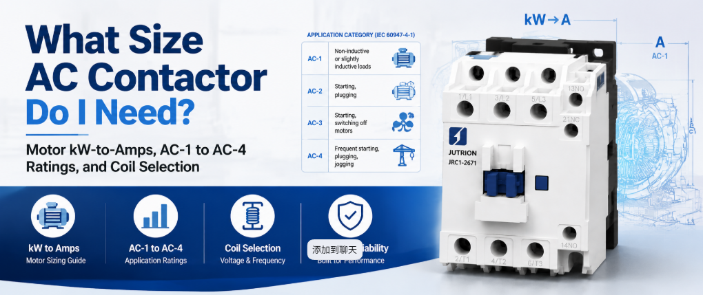
إجابة سريعة: ما وظيفة الكونتاكتور AC؟
الكونتاكتور AC هو مفتاح كهربائي يتم التحكم فيه كهربائيًا يستخدم ملفًا مغناطيسيًا كهربائيًا لتوصيل وفصل دائرة الطاقة عند الطلب، وهو مصمم للقيام بذلك آلاف إلى ملايين المرات دون أن تلتحم أو تتآكل نقاط التلامس. يقوم بتبديل تيار الحمل عند الطلب. لا يحمي الدائرة. يعني تحديد حجمه بشكل صحيح تحديده وفقًا للتصنيف الذي ينطبق على حملك الفعلي، وليس أعلى رقم مطبوع على الملصق.
الكونتاكتور المصنف 20 A ليس جهازًا بقدرة 20 A لمحرك. قد يكون نفس الوحدة الفيزيائية مصنفة 20 A لسخان مقاوم و9 A لمحرك بقفص سنجابي، لأن اندفاع المحرك والكسر الحثي يؤثران على نقاط التلامس بشكل أشد من السخان. هذا التمييز الوحيد يسبب أكثر حالات فشل الكونتاكتور المبكرة مقارنة بأي خطأ اختيار آخر.
يغطي هذا الدليل ما يجب أن يحمله الموصل، وكيفية حسابه، وفئة الاستخدام المطبقة، وفحوصات الأقطاب والملف والملحقات والعمر والتنسيق التي تتبع رقم الأمبير.
طابق مهمة التبديل مع الجهاز المناسب
قبل تحديد حجم أي شيء، تأكد من أن الموصل هو الجهاز الصحيح للمهمة. تفشل تصميمات اللوحات بشكل متكرر لأن أحد المكونات يُتوقع منه أداء وظيفتين غير مرتبطتين.
| الجهاز | المهمة الأساسية | تردد التبديل | يفصل عند العطل |
|---|---|---|---|
| كونتاكتور AC | إنشاء وفصل تيار الحمل عند الطلب | مصمم للتدوير المتكرر | لا. يتطلب مرحل حمل زائد منفصل أو قاطع دائرة |
| مرحل للأغراض العامة | تبديل الطاقة المنخفضة والتحكم في الإشارات | مصنف لواجب أخف | لا |
| MCB أو MCCB | حماية من التيار الزائد وقصر الدائرة | تشغيل عرضي، وليس تدويرًا روتينيًا | نعم |
| مشغل المحرك | موصل ومرحل حمل زائد في تجميع واحد | نفس الموصل | نعم، من خلال مرحل الحمل الزائد |
| مشغل ناعم أو محرك تردد متغير | تسارع متحكم به لتيار المحرك | تحكم مستمر بدلاً من تشغيل/إيقاف | يختلف حسب الطراز |
إذا كان السؤال هو كيفية تشغيل وإيقاف حمل بشكل متكرر عند الطلب، فإن الإجابة هي كونتاكتور. إذا كان السؤال هو ما الذي يحمي الدائرة من الحمل الزائد، فهذا جهاز مختلف. التعامل مع الكونتاكتور كما لو كان يقوم بالأمرين معًا هو أحد أكثر أخطاء تصميم اللوحات شيوعًا.
لماذا لا يمكن لمرحل أو قاطع دائرة أن يحل محله
يمكن لمرحل للأغراض العامة إغلاق دائرة، لكنه غير مصمم للقيام بذلك عند مستويات تيار المحرك أو السخان على المدى الطويل. الموصلات مصنفة لعمر ميكانيكي يصل إلى ملايين العمليات، بينما المرحلات العامة مصنفة لجزء صغير من ذلك تحت حمل كهربائي حقيقي. يكمن الفرق في مادة نقاط التلامس، وقوة الزنبرك، وإخماد القوس. تستخدم الموصلات هندسة التلامس، وعلى الإطارات الأكبر، قنوات القوس اللازمة لكسر تيار المحرك الحثي بشكل متكرر دون تنقر أو لحام نقاط التلامس. المرحل الذي يُدفع إلى هذا الواجب يفشل عادةً باللحام مغلقًا تحت الحمل، وهو وضع فشل أسوأ بكثير من التآكل التدريجي للموصل.
قاطع الدائرة مصمم لحماية الدائرة وتشغيله من حين لآخر، وليس لتدويره كجزء من منطق الأتمتة العادي. استخدام قاطع كمفتاح واجب يقصر عمره الوقائي وليس ما هو مصنف له. الكونتاكتور والجهاز الوقائي يقومان بوظيفتين مختلفتين وينتميان إلى نفس الدائرة معًا.
كيف يعمل الكونتاكتور AC
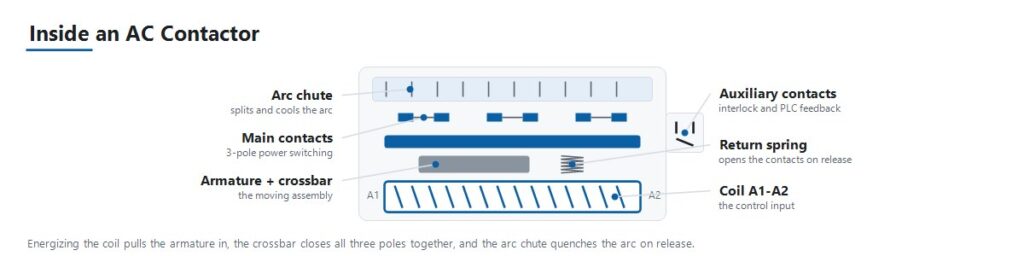
يشرح تسلسل التشغيل معظم أوضاع الفشل المغطاة لاحقًا في هذا الدليل.
- إشارة التحكم تنشط الملف. دائرة تحكم، مثل مخرج PLC أو منظم حرارة أو منطق أزرار ضغط، تطبق الجهد على الملف بجهد الملف المقدر.
- المغناطيس الكهربائي يسحب العضو المتحرك. الملف النشط يخلق مجالًا مغناطيسيًا يجذب عضوًا متحركًا نحو قلب ثابت.
- نقاط التلامس الرئيسية تغلق. حركة العضو المتحرك تغلق نقاط التلامس الرئيسية للطاقة من خلال قضيب متقاطع مشترك، وتربط الحمل بالإمداد.
- نقاط التلامس المساعدة تغير حالتها. نقاط تلامس مساعدة صغيرة مرتبطة بنفس العضو المتحرك تفتح أو تغلق بالتزامن مع نقاط التلامس الرئيسية. توفر التعشيق والإشارة والتأكيد إلى PLC بأن الموصل أغلق بالفعل.
- قوة الزنبرك تحافظ على ضغط التلامس. ضغط التلامس المستقر تحت الاهتزاز والحمل هو ما يمنع ارتداد التلامس والتسخين المقاوم على سطح التلامس.
- يؤدي إزالة الطاقة عن الملف إلى فتح الدائرة. عندما تنخفض إشارة التحكم، ينهار المجال المغناطيسي ويقوم زنبرك الإرجاع بسحب العضو المتحرك إلى الخلف، مما يفتح نقاط التلامس الرئيسية.
- يتولى إخماد القوس الكهربائي عملية القطع. يؤدي فتح دائرة تحت الحمل، خاصة حمل محرك حثي، إلى سحب قوس كهربائي عبر نقاط التلامس المنفصلة. وتعمل هندسة نقاط التلامس ومزالق القوس الكهربائي على إطفاء ذلك القوس بسرعة كافية لمنع التلف في كل دورة.
فئات الاستخدام تحدد تصنيف التيار الحقيقي
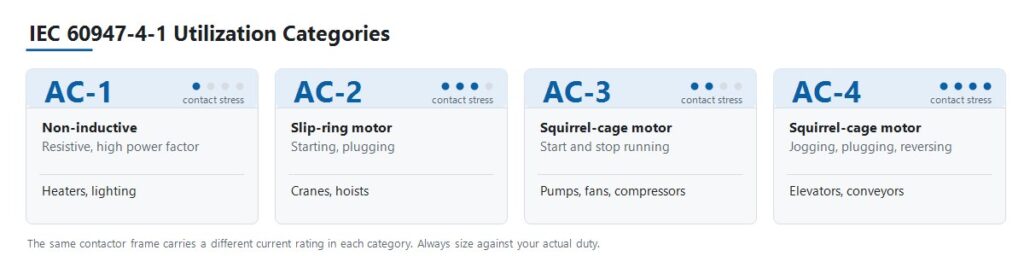
تعرف المواصفة IEC 60947-4-1 فئات استخدام تصف مدى قسوة الحمل على نقاط التلامس، وليس ببساطة عدد الأمبيرات التي يسحبها. هذه هي الخطوة التي تعود إليها معظم أخطاء الاختيار.
| الفئة | نوع الحمل | واجب التبديل | التطبيق النموذجي |
|---|---|---|---|
| AC-1 | غير حثي أو حثي قليلاً، معامل قدرة مرتفع | لا يوجد تيار اندفاع كبير | سخانات مقاومة، مجموعات تدفئة HVAC، إضاءة عامة |
| AC-2 | محركات ذات حلقات انزلاق (دوار ملفوف) | بدء التشغيل والكبح العكسي تحت الحمل | الرافعات، الروافع |
| AC-3 | محركات ذات قفص سنجابي | بدء التشغيل، وإيقاف تشغيل محرك يعمل | المضخات، المراوح، الضواغط |
| AC-4 | محركات ذات قفص سنجابي | الحركة النبضية، الكبح العكسي، العكس السريع | المصاعد، الناقلات، أدوات الآلات |
النتيجة هي أن الكونتاكتور الواحد يحمل عدة تصنيفات تيار مختلفة. JUTRION JRC1-D09 مصنف 20 A في الفئة AC-1 و9 A في الفئة AC-3. كلا الرقمين يصفان نفس الجهاز الفيزيائي. تحديد حجم مضخة بناءً على رقم 20 A يضع الكونتاكتور بأكثر من ضعف تصنيفه لحمل المحرك، وستظهر نقاط التلامس ذلك.
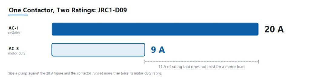
اقرأ كل تصنيف منشور مع الفئة التي ينتمي إليها. الهيكل ليس نموذج رافعة أو نموذج حركة نبضية. إنه هيكل واحد بعدة تصنيفات، والواجب هو الذي يحدد التصنيف الذي ينطبق على المشروع.
حوّل بيانات المحرك إلى أمبير
استخدم تيار الحمل الكامل المتحقق منه مباشرة عندما يوفره المشروع بالفعل. عندما تُعطى البيانات كقدرة محرك، حوّلها باستخدام الجهد وترتيب الأطوار الصحيحين.
المحركات ثلاثية الأطوار
I = P × 1,000 / (√3 × VLL × cos φ × η)
الأحمال أحادية الطور
I = P × 1,000 / (V × cos φ × η)
هنا،, I هو تيار الخط بالأمبير،, P هي قدرة الخرج المقدرة للمحرك بالكيلوواط،, VLL هو جهد الخط إلى الخط ثلاثي الأطوار،, V هو الجهد أحادي الطور،, cos φ هو معامل القدرة، و η هي الكفاءة.
عامل القدرة لمحركات الحث القياسية عادة ما يكون بين 0.80 و0.88، والكفاءة بين 0.85 و0.93 حسب فئة الكفاءة. استخدم قيم لوحة الاسم متى ما كانت متوفرة. النطاقات النموذجية مخصصة للعمل التمهيدي قبل وصول ورقة بيانات المحرك.
بالنسبة للأحمال أحادية الطور المقاومة البحتة مثل عناصر التسخين، يكون معامل القدرة والكفاءة مساويين للواحد فعليًا، ويُختزل التعبير إلى I = P × 1,000 / V.
فئة حاسبة تحديد حجم كونتاكتور AC من JUTRION تقوم بالحساب نفسه وتُرجع حدًا أدنى لتيار التشغيل AC-3. إنها نقطة بداية للمواصفات، وليست بديلاً عن لوحة بيانات المحرك أو جداول التصنيف الخاصة بالشركة المصنعة.
تطبيق معاملات نوع الحمل وتخفيض القدرة حسب درجة الحرارة المحيطة
تسحب بعض الأحمال تيارًا يفوق تيار حالتها المستقرة بكثير لحظة التوصيل. وتقضي الممارسة الصناعية الراسخة بتطبيق معامل لمراعاة هذا السلوك. وهذه القواعد التقليدية ليست قيمًا محددة في المواصفة IEC 60947-4-1، لذا تعامل معها كتقدير أولي وتأكد منها مقابل بيانات تيار البدء الفعلية للدوائر الحرجة أو الكبيرة.
| نوع الحمل | المعامل التقليدي | السبب |
|---|---|---|
| مجموعات المكثفات | حوالي 1.5 × التيار المقنن للمكثف | تيار البدء السعوي عند التوصيل شديد وقصير جدًا |
| المحولات وماكينات اللحام | حوالي 2 × التيار المقنن | يمكن أن يصل تيار البدء المغنطيسي إلى أضعاف تيار الحالة المستقرة |
| إضاءة التفريغ الغازي والإضاءة عالية الشدة (HID) | حوالي 1.1 إلى 1.4 × التيار المقنن | تيار بدء الكابح وسلوك الإحماء |
| تبريد رديء أو حاوية مكتظة بالعناصر | 110 إلى 120 بالمائة من التيار المقنن للحمل | ارتفاع درجة الحرارة الداخلية يقلل من سعة التيار |
| محرك يعمل باستمرار، تشغيل طويل | التيار المقنن للموصل يُخفض بنحو 30 بالمائة | تحميل حراري مستمر لنقاط التلامس |
درجة الحرارة المحيطة وظروف الحاوية
يفترض التيار المقنن للموصل درجة الحرارة المحيطة المرجعية المذكورة في ورقة بياناته. وفوق تلك الدرجة، تنخفض سعة حمل التيار، لكن منحنى التخفيض خاص بالشركة المصنعة وبالهيكل. استخدم منحنى التخفيض من وثائق المنتج الفعلية بدلًا من نسبة مئوية عامة.
يسري شرطان بغض النظر عن المنتج. أولًا، اجعل الحساب مبنيًا على درجة الحرارة داخل الحاوية، لا درجة حرارة الغرفة. فاللوحة المكتظة بالعناصر في منشأة دافئة تسخن داخليًا أكثر بكثير من المحيط. ثانيًا، الموصلات المركبة جنبًا إلى جنب دون مسافات تسخن بعضها بعضًا، لذا التزم بالمسافة الدنيا التي تحددها الشركة المصنعة أو خفّض القدرة أكثر.
مثال عملي: محرك مضخة 4 كيلوواط عند 400 فولت
محرك مضخة طرد مركزي ثلاثي الطور في لوحة معالجة مياه OEM. واجب تشغيل وإيقاف قياسي، حوالي 20 بدء تشغيل في الساعة، ودرجة حرارة اللوحة حوالي 35 °C.
الخطوة 1. تحديد فئة الاستخدام. المحرك الحثي ذو القفص السنجابي، الذي يُشغَّل ويُوقَف بشكل طبيعي، يندرج ضمن الفئة AC-3. وهو ليس AC-1، حتى لو وُصف الحمل بأنه مضخة بسيطة.
الخطوة 2. حساب تيار الحمل الكامل. قيم لوحة الاسم هي 4 كيلوواط، 400 فولت، cos φ = 0.85، η = 0.90.
I = 4 × 1,000 / (1.732 × 400 × 0.85 × 0.90)
حساب المقام: 1.732 × 400 = 692.8، ثم × 0.85 = 588.9، ثم × 0.90 = 530.0.
I = 4,000 / 530.0 ≈ 7.6 A
الخطوة 3. الاختيار وفقًا لتصنيف AC-3. المطلوب هو كونتاكتور بتصنيف AC-3 يغطي 7.6 A مع هامش. JRC1-D09 مصنف 9 A عند AC-3، مما يوفر حوالي 18 بالمئة هامش فوق التيار الكامل المحسوب. لاحظ ما لم يتم: نفس JRC1-D09 يحمل تصنيف 20 A عند AC-1، وتحديد حجم هذه المضخة بناءً على هذا الرقم سيكون الخطأ الأكثر شيوعًا في اختيار الكونتاكتور.
الخطوة 4. التحقق من درجة الحرارة المحيطة ونظام التشغيل. عند درجة حرارة اللوحة 35 °C مع هامش 18 بالمئة، تحقق من الرقم مقابل منحنى تخفيض التصنيف للمنتج قبل الالتزام. هذا الهامش مريح في لوحة جيدة التهوية وأضيق في لوحة مكتظة. عند 20 بدء تشغيل في الساعة، تأكد من أن عدد العمليات المصنفة في الساعة والعمر الكهربائي AC-3 يتجاوزان واجب العمل المتوقع طوال عمر خدمة اللوحة.
الخطوة 5. تحديد جهد الملف. ثانوي محول التحكم في اللوحة هو 220 فولت AC، لذا تم تحديد ملف الملف عند 220 فولت. ليس 400 فولت، رغم أن المحرك يعمل عند 400 فولت.
الخطوة 6. إضافة الحماية. قم بإقران الكونتاكتور بمرحل حماية من الحمل الزائد بحجم صحيح مضبوط على تيار الحمل الكامل للمحرك، وتأكد من التنسيق من النوع 1 أو النوع 2 مع القاطع أو المصهر العلوي. تشير البداية العادية التي تقل عن 10 ثوانٍ إلى فئة تعثر من الفئة 10 هنا. حاسبة ضبط مرحل الحمل الزائد تحوّل تيار اللوحة، ومعامل الخدمة، ومدة البدء إلى ضبط أولي وفئة تعثر.
النتيجة: كونتاكتور JRC1-D09، ثلاثي الأقطاب، مع ملف 220 فولت AC، بالإضافة إلى مرحل حماية من الحمل الزائد. تم اختيار الحجم بناءً على الحمل، وليس من الكتالوج.
ينطبق نفس الإجراء على القدرة الأعلى. محرك 18.5 كيلوواط عند 400 فولت يعادل تقريبًا 35 A تيار حمل كامل ويتطلب كونتاكتور بتصنيف AC-3 أعلى من هذا الرقم.
استخدم هذه العملية المكونة من سبع خطوات لاختيار كونتاكتور AC
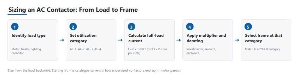
الخطوة 1: تحديد نوع الحمل وفئة الاستخدام
حدد ما إذا كان الحمل مقاوميًا، أو محرك قفص سنجابي قياسي، أو محرك دوار ملفوف يبدأ تحت حمل، أو محرك يخضع للتشغيل المتقطع والعكس. كل ما يلي يعتمد على هذه الإجابة، لأنها تحدد أي من تصنيفات التيار المتعددة للكونتاكتور ينطبق فعليًا.
الخطوة 2: حساب التيار التشغيلي وتأكيد الجهد
استخدم المعادلات أعلاه للحصول على تيار الحمل الكامل، وطبّق مضاعف نوع الحمل ذي الصلة، ثم تأكد من أن التيار التشغيلي المقنن Ie في فئة الاستخدام الخاصة بك يغطيه بهامش. طابق الجهد التشغيلي المقنن Ue إلى جهد خط النظام.
الخطوة 3: اختيار جهد الملف
جهد الملف هو مواصفة منفصلة عن جهد الحمل. قد يتم تبديل دائرة محرك 380 فولت بواسطة ملف 24 فولت DC أو 220 فولت AC حسب هندسة التحكم. تحقق مما يزوده فعليًا دائرة التحكم، سواء كان خرج PLC أو ثانوي محول تحكم أو مصدر DC، قبل الطلب.
الخطوة 4: اختيار عدد الأقطاب والتكوين
ثلاثة أقطاب هو المعيار لأحمال المحركات ثلاثية الطور. يُستخدم أربعة أقطاب حيث يكون التبديل المحايد أو دائرة مستقلة إضافية مطلوبًا. تأكد من التوافق مع تصميم التأريض للنظام، حيث أن التبديل المحايد مطلوب في بعض الأنظمة وغير ضروري أو محظور في أنظمة أخرى.
الخطوة 5: تحديد جهات الاتصال المساعدة
حدد عدد جهات الاتصال المساعدة المفتوحة عادةً والمغلقة عادةً اللازمة للترابط، وتغذية حالة PLC، ومصابيح المؤشر، وما إذا كانت مدمجة أو مضافة ككتلة مساعدة منفصلة. في مشغل مباشر قياسي، جهة اتصال مساعدة موصولة بالتوازي مع زر البدء هي ما يثبت دائرة التحكم بحيث يبقى الملامس نشطًا بعد أن يحرر المشغل الزر. جهات الاتصال المساعدة غير مكلفة لتحديدها في مرحلة التصميم وصعبة التركيب لاحقًا.
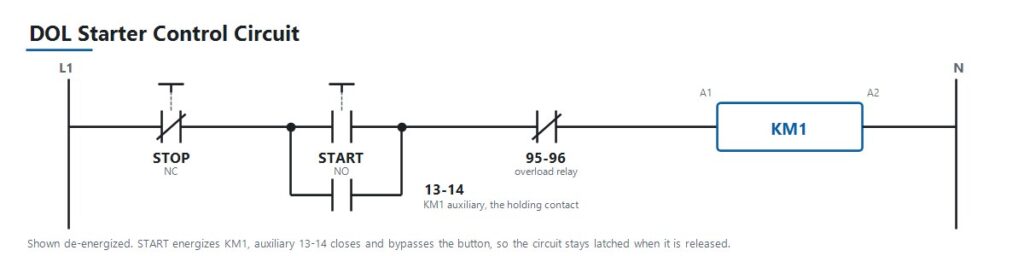
الخطوة 6: التحقق من العمر الكهربائي مقابل دورة التشغيل الفعلية
للتطبيقات ذات التشغيل المتكرر مثل النبض أو عكس الاتجاه أو تسلسلات الأتمتة عالية التردد، تحقق من عدد العمليات المقدرة في الساعة والعمر الكهربائي في فئة الاستخدام الخاصة بك. العمر الميكانيكي، المقاس بدون حمل، هو دائمًا الرقم الأعلى والأقل صلة.
الخطوة 7: التنسيق مع الحماية العلوية
قم بإقران الملامس مع مرحل حمل زائد بحجم مناسب لأحمال المحركات، ثم قم بالتنسيق مع قاطع أو مصهر علوي بحجم مناسب للحماية من قصر الدائرة. في لوحات التوزيع الأكبر، غالبًا ما يكون هذا الجهاز العلوي قاطع دائرة هوائي. اختيار الملامس هو حلقة واحدة في سلسلة تمتد من تيار الحمل إلى تصنيف القاطع إلى تيار العطل المتوقع إلى واجب كسر الجهاز. اختيار الملامس بشكل صحيح مع ترك تلك السلسلة غير محققة ينقل المشكلة فقط.
تصنيفات IEC 60947-4-1 وNEMA ليست تسميات قابلة للتبادل
الكونتاكتورات AC المباعة دوليًا تُصنع عمومًا وفقًا لـ IEC 60947-4-1، الذي يحدد فئات الاستخدام وهيكل التصنيف المستخدم في هذا الدليل. تم نشر الطبعة الخامسة الحالية في 2023 وتلغي طبعة 2018. من المفيد التحقق من الطبعة التي تشير إليها مواصفات المشروع، لأنها ليست متطابقة.
تشير الأسواق في أمريكا الشمالية عادةً إلى تصنيفات ملامسات NEMA ICS 2 بدلاً من فئات الاستخدام IEC أو بجانبها. يصنف النظامان الملامسات بشكل مختلف، حيث يستخدم NEMA فئات الحجم بدلاً من AC-1 إلى AC-4. المواصفات المكتوبة لسوق واحد لا تترجم تلقائيًا إلى الآخر. عند التوريد لمشروع في أمريكا الشمالية، تأكد من الإطار الذي تتطلبه مواصفات المشتري فعليًا قبل اقتباس جزء.
تعامل مع معيار المنتج ورمز التركيب وأي متطلب خاص بالسوق كثلاثة أسئلة منفصلة. تأكيد واحد لا يجيب على الآخرين.
التنسيق من النوع 1 والنوع 2
يحدد التنسيق ضد قصر الدائرة وفقًا لـ IEC 60947-4-1 مقدار الضرر الذي يسببه العطل للملامس والمشغل. يسمح النوع 1 بتلف المعدات بعد عطل قصر الدائرة، بشرط أن يكون الضرر محتويًا ولا ينتج عنه خطر، وقد تتطلب المعدات إصلاحًا أو استبدالًا. يتطلب النوع 2 أن تظل المعدات مناسبة للاستخدام المستقبلي، مع السماح فقط بلحام خفيف لجهات الاتصال. هذه نتائج تجارية وهندسية مختلفة. تأكد من النوع الذي تتطلبه مواصفات المشروع قبل اختيار المجموعة.
الاختيار بين تصنيفات JUTRION JRC1
تصنع JUTRION كونتاكتور AC من سلسلة JRC1 على خطوط إنتاجه الخاصة في ونتشو، تشجيانغ، مصمم وفقًا لـ IEC 60947-4-1. خيارات جهد الملف تشمل 24 فولت، 48 فولت، 110 فولت، 220 فولت، و380 إلى 415 فولت عند 50 أو 60 هرتز. يتم اختبار كل وحدة من حيث التشغيل الميكانيكي، أداء الملف، والتبديل الكهربائي قبل الشحن.
فيما يلي نقاط التصنيف المنشورة عبر فئات الاستخدام الأربع. اقرأ الجدول حسب الفئة بدلاً من الطراز، حيث يظهر نفس الإطار تحت أكثر من فئة بتصنيف مختلف.
| الفئة | نقطة التصنيف | الواجب الذي يمثله هذا |
|---|---|---|
| AC-1 | JRC1-D09، 20 A | سخانات مقاومة، مجموعات تدفئة HVAC، إضاءة عامة |
| AC-2 | JRC1-D25، 25 A | محركات ذات دوار ملفوف تبدأ تحت الحمل، رافعات وروافع |
| AC-3 | JRC1-D09، 9 A | محركات قفص السنجاب، بدء وإيقاف عادي، مضخات ومراوح |
| AC-4 | JRC1-D18، 7.7 A | التشغيل النبضي، والكبح بالتيار المعاكس، والعكس السريع، والمصاعد والناقلات |
يظهر JRC1-D09 مرتين، عند 20 A تحت AC-1 و9 A تحت AC-3، لأن هذين تصنيفين لنفس الكونتاكتور الفيزيائي تحت واجبين مختلفين. لدائرة محرك حث قياسية، التي تغطي غالبية تطبيقات المضخات والمراوح والضواغط، حدد الحجم بناءً على تصنيف AC-3 كما في المثال العملي. لواجب التشغيل بالتنقل أو العكس، حدد الحجم بناءً على AC-4 حيث يحمل نفس الإطار تيارًا أقل بكثير.
تصنيفات الإطار فوق هذه النقاط المنشورة متاحة. يجب أن يعتمد اختيار الطراز النهائي على التصنيفات الخاصة بالطراز وظروف المشروع، وليس على رقم تيار فقط.
طبق منطق الاختيار على خمسة سيناريوهات لوحات
لوحة محرك قياسية للمضخات والمراوح والضواغط
يقوم OEM لبناء لوحات تحكم HVAC أو معدات معالجة المياه بتحديد كونتاكتورات لواجب بدء وإيقاف المحرك البسيط. هذه هي الفئة AC-3. حدد تصنيف AC-3 مقابل التيار الكامل المحسوب، وقم بإقرانه بمرحل حماية من الحمل الزائد بالحجم الصحيح، ووافق جهد الملف مع خرج محول التحكم في اللوحة.
لوحة رافعة أو ونش مع محركات ذات دوار ملفوف
يتطلب OEM رافعة كونتاكتورات تتحمل بدء تشغيل عزم دوران عالي وواجب التوصيل العكسي على محركات ذات دوار ملفوف، وهي الفئة AC-2. هذه الأحمال أكثر إجهادًا على التلامسات من واجب AC-3 القياسي بسبب التكرار في بدء التشغيل تحت الحمل والعكس. التقليل في الحجم هنا يظهر كاهتراء مبكر للتلامسات بدلاً من فشل فوري، مما يسهل تشخيصه خطأً كمشكلة جودة.
التحكم في المصعد أو الناقل مع الحركة النبضية وعكس الاتجاه
يحتاج مصنع الآلات إلى موصلات لتطبيق يتضمن عكس اتجاه متكرر وحركات دقيقة، وهي الفئة AC-4، الأكثر تطلبًا من بين الفئات الأربع. العمر الكهربائي بمعدل العمليات الفعلي في الساعة مهم هنا أكثر من أي سيناريو آخر. التقليل في حجم هذه الفئة هو أسرع طريقة لاستهلاك العمر المقدر للموصل.
تبديل بنك المكثفات لتصحيح معامل القدرة
منشأة تضيف مكثفات تصحيح معامل القدرة تحتاج إلى موصلات مصممة وفقًا لتيار الاندفاع السعوي، تقليديًا حوالي 1.5 مرة من التيار المقدر للمكثف، وغالبًا ما تُحدد بمقاومات شحن مسبق أو كموصلات تبديل مكثفات مخصصة. الحجم القياسي AC-1 غير كافٍ، لأن الاندفاع السعوي هو واجب تبديل متميز وليس نسخة خفيفة من الواجب المقاوم.
لوحة التدفئة المقاومة أو الإضاءة
مصنع لوحات يقوم بتبديل مجموعات التدفئة HVAC أو أحمال إضاءة كبيرة يعمل في الفئة AC-1، الأقل تطلبًا، حيث لا يوجد اندفاع كبير أو ارتداد حثي لإدارته. إضاءة التفريغ و HID هي الاستثناء وتتطلب مضاعف 1.1 إلى 1.4 لاندفاع الصابورة. هذه أيضًا حالة حيث يبالغ المشترون أحيانًا في التحديد باختيار جزء مقدر بـ AC-3 حيث كان AC-1 كافيًا، وهو ليس غير آمن، فقط تكلفة غير ضرورية.
تجنب الأخطاء التسعة التي تسبب فشل الموصل المبكر
| الخطأ | النتيجة | الوقاية |
|---|---|---|
| التحجيم وفقًا لتصنيف AC-1 لحمل المحرك | موصل أصغر من الحجم المطلوب لواجبه الفعلي، تلتحم نقاط التلامس أو تتآكل مبكرًا | قم دائماً باختيار المقاس وفقاً للتصنيف الخاص بفئة الاستخدام الفعلية |
| إغفال مرحل الحمل الزائد | المحرك والكونتاكتور كلاهما معرضان لتيار زائد مستمر | اقترن كل دائرة محرك بمرحل حمل زائد بالمقاس الصحيح |
| تجاهل تردد التبديل مقابل العمر الكهربائي | الكونتاكتور ذو التيار المحدد بشكل صحيح يفشل مبكراً في الخدمة عالية الدورات | تحقق من العمليات المقدرة في الساعة والعمر الكهربائي عند فئتك |
| جهد الملف غير متطابق | الكونتاكتور يفشل في الجذب، أو يحترق الملف | تأكد مقابل جهد دائرة التحكم الفعلي، وليس جهد الحمل |
| عدم فحص التنسيق مع المنبع | عطل الدائرة القصيرة يدمر الكونتاكتور دون داعٍ | تحقق من التنسيق من النوع 1 أو النوع 2 قبل إنهاء التصميم |
| كونتاكتورات العكس بدون تعشيق | يمكن لكلا الكونتاكتورين الإغلاق معاً، مما يخلق قصراً بين الأطوار | حدد كلاً من التعشيق الميكانيكي والكهربائي على أزواج العكس |
| تجاهل درجة الحرارة المحيطة وتخفيض تصنيف الحاوية | عمر مختصر رغم صحة كل المواصفات الأخرى | خفّض التصنيف باستخدام منحنى المنتج ودرجة حرارة الحاوية |
| نسيان مضاعف نوع الحمل | تيار الإدخال للمكثف أو المحول أو الإضاءة يُتلف الملامسات بمرور الوقت | طبّق المضاعف التقليدي لنوع الحمل |
| تحديد الملامسات المساعدة متأخراً جداً | إعادة عمل اللوحة المكلفة أو كتل الإضافة غير الملائمة | حدد احتياجات التعشيق والتغذية الراجعة في مرحلة التصميم |
تركيب وتشغيل وتشخيص الكونتاكتور
معظم أعطال الكونتاكتور المُبلَّغ عنها كعيوب في المنتج هي أعراض لمشكلة في المقاس أو التنسيق أو مصدر التحكم. يربط الجدول أدناه الأعراض الشائعة بالفحوصات التي تحدد السبب.
| العَرَض | الأسباب المحتملة | فحوصات مفيدة |
|---|---|---|
| اهتزاز أو طنين بصوت عالٍ | جهد ملف منخفض أو غير مستقر، ملف تظليل متآكل، قلب مغناطيسي متسخ أو مرتخٍ | قس جهد الملف تحت الحمل، افحص وجه القلب، تحقق من استقرار مصدر التحكم |
| ملامسات ملحومة مغلقة | مقاس أصغر من الفئة الفعلية، حدث دائرة قصيرة بدون تنسيق كافٍ، تردد تبديل مفرط | تحقق من مقاس الفئة، راجع سجل الأعطال في المنبع، قارن العمليات في الساعة مقابل العمر الكهربائي المقدر |
| لا جذب رغم وجود إشارة التحكم | ملف مفتوح الدائرة، جهد ملف خاطئ، ارتباط ميكانيكي، مصهر تحكم محترق | قس مقاومة الملف والجهد عند الأطراف، افحص مصهر التحكم، ابحث عن عوائق |
| ملامسات متنقرة أو محترقة | تآكل طبيعي في نهاية العمر، مقاس أصغر من فئة الخدمة، إخماد قوس ضعيف عند تردد تبديل عالٍ | قارن الحالة مقابل العمر الكهربائي المقدر، أعد التحقق من مقاس الفئة، افحص غرفة الإخماد |
| التغذية الراجعة المساعدة لا تتوافق مع حالة الملامس الرئيسي | كتلة مساعدة متآكلة أو غير محاذاة، تآكل في الوصلة الميكانيكية | اختبر استمرارية المساعد بشكل مستقل، افحص الوصلة إلى مجموعة الملامس الرئيسي |
| ارتفاع حرارة الأطراف | توصيل مرتخٍ، موصل بمقاس أصغر، عزم خاطئ عند التركيب | تحقق من عزم الطرف مقابل المواصفات، تحقق من مقاس الموصل، صوّر حرارياً تحت الحمل |
| الملف يحترق بشكل متكرر | جهد زائد مستمر على دائرة التحكم، درجة حرارة محيطة مفرطة، ارتباط ميكانيكي يمنع الجذب الكامل | قس جهد التحكم تحت جميع ظروف التشغيل، افحص الارتباط، تحقق من درجة الحرارة المحيطة |
الأعطال المبكرة المتكررة في نفس التطبيق تشير دائماً تقريباً إلى عدم تطابق في المقاس أو التنسيق أو دورة الخدمة بدلاً من دفعة معيبة. شخّص السبب قبل إعادة طلب نفس رقم القطعة.
حماية الملف وأي شيء يقوم بتشغيله
إيقاف تنشيط ملف حثي ينتج عنه انتقال جهد. عندما يقوم خرج ترانزستور PLC أو مرحل وسيط صغير أو متحكم إلكتروني بتبديل هذا الملف مباشرة، ينتقل الانتقال إلى الوراء إليه. هذا سبب روتيني لفشل خرج PLC وتآكل التلامسات في المرحلات الوسيطة، ومن السهل تصميم حل له. استخدم مقاوم-مكثف RC عبر ملفات AC، ودايود فليب باك أو فارستور على ملفات DC. لاحظ المقايضة: دايود فليب باك بسيط يطيل وقت الانقطاع بشكل ملحوظ، وهو أمر مهم عندما يكون الكونتاكتور جزءًا من وظيفة إيقاف متعلقة بالسلامة مع زمن استجابة محدد.
تأكد من تفاوت جهد تشغيل الملف بدلاً من افتراض أن القيمة الاسمية ثابتة. قد يؤدي امتداد كابل التحكم الطويل أو محول تحكم صغير الحجم إلى خفض جهد الملف الفعلي إلى ما دون النطاق الذي سيجذب فيه الملف ويستمر، وتظهر الأعراض على شكل اهتزاز بدلاً من عطل أسلاك واضح.
اذكر هذه المعلمات عند طلب عرض سعر
يمكن الرد على استفسار الكونتاكتور الذي يتضمن المعلومات التالية بطراز محدد في الرد الأول. أما الاستفسار الذي يعطي رقم أمبير فقط فيتطلب عادة عدة جولات من التوضيح، لأن قيمة التيار المجردة لا تحدد الخدمة التي تنطبق عليها.
- التطبيق أو المعدات التي يتم التحكم بها
- نوع الحمل: محرك، سخان، إضاءة، مكثف، أو محول
- فئة الاستخدام، إذا كانت محددة مسبقاً
- القدرة المقدرة للمحرك بالكيلوواط، أو الحمل بالكيلوواط
- جهد النظام وتردده
- تيار الحمل الكامل المحسوب
- الخدمة: عدد مرات البدء في الساعة، وما إذا كان التطبيق يعكس الاتجاه أو يعمل بنبضات
- جهد الملف المطلوب، وما إذا كان AC أو DC
- عدد الأقطاب، ثلاثي أو رباعي
- نقاط التلامس المساعدة المطلوبة، مفتوحة عادة ومغلقة عادة
- جهاز الحماية الأولي، قاطع أو مصهر
- درجة الحرارة المحيطة بلوحة التحكم
- ترتيب التركيب، سكة DIN أو براغي
- كمية الطلب والسوق المستهدف
- أي متطلبات OEM أو ODM
الأسئلة الشائعة
ما الفرق بين كونتاكتور AC ومشغل محرك؟
مُشغِّل المحرك هو مُلامس مدمج مع مرحل حماية من الحمل الزائد في مجموعة واحدة، مُصمم خصيصًا لدوائر المحركات. يوفر الملامس المستقل وظيفة التبديل فقط، وتُضاف حماية الحمل الزائد بشكل منفصل.
هل يمكن استخدام كونتاكتور واحد لكل من أحمال AC-1 وAC-3؟
عادةً ما يكون الكونتاكتور الفيزيائي نفسه مقدراً لعدة فئات، ولكن بتقدير تيار مختلف لكل فئة. اختر الحجم وفقاً للتقدير الذي يطابق فئة استخدام الحمل الفعلي، وليس أعلى رقم على الملصق.
كيف أحسب التيار لتحديد حجم الكونتاكتور؟
لمحرك ثلاثي الطور، استخدم I = P × 1,000 / (√3 × VLL × cos φ × η)، حيث P هي القدرة المقدرة بالكيلوواط، وVLL هي جهد الخط إلى الخط، وcos φ هو معامل القدرة، وη هي الكفاءة. ثم طبّق أي مضاعف لنوع الحمل وتأكد من النتيجة مقابل تقدير الكونتاكتور عند فئة الاستخدام الخاصة بك.
هل يكون الملامس الأكبر دائمًا أكثر أمانًا؟
لا. الإفراط في الحجم يهدر التكلفة ومساحة اللوحة، وعلى بعض الأحمال تحمل نقاط تلامس كونتاكتور مفرط الحجم تياراً قليلاً جداً لتبقى نظيفة. اختر الحجم بهامش معقول فوق تيار الحمل الكامل المحسوب عند الفئة الصحيحة بدلاً من القفز بمقاسين.
ما جهد الملف الذي يجب أن أختاره؟
وافقه مع ما تزوده دائرة التحكم فعليًا، سواء كان خرج PLC أو ثانوي محول تحكم أو مصدر DC للوحة. ليس جهد جانب الحمل الذي يبدله الكونتاكتور.
لماذا يصدر الكونتاكتور الخاص بي طنينًا أو قرقعة؟
الأسباب المعتادة هي جهد ملف منخفض أو غير مستقر أو غير صحيح، أو تلف أو اتساخ وجه النواة المغناطيسية في وحدة ملف AC. قس جهد الملف تحت ظروف الحمل الفعلية وافحص وجه النواة قبل استنتاج أن الوحدة معطلة.
هل ما زلت بحاجة إلى مرحّل حِمل زائد إذا كنت أستخدم موصّلًا؟
نعم، لدوائر المحركات. الكونتاكتور يبدّل عند الأمر لكنه لا يفصل عند التيار الزائد المستمر، وهذه وظيفة مرحل الحمل الزائد. الجهازان يعملان معاً ولا يحل أحدهما محل الآخر.
كم عدد دورات التشغيل التي يمكن أن يتحملها الكونتاكتور؟
يعتمد ذلك على حجم الإطار، والأهم من ذلك، على فئة الاستخدام ومستوى التيار الذي يعمل به. العمر الميكانيكي المُقاس بدون حمل عادةً ما يكون أعلى بكثير من العمر الكهربائي تحت الحمل، وينخفض العمر الكهربائي أكثر عند ترددات التبديل الأعلى. تحقق من العمر الكهربائي المُصنّف عند دورة التشغيل الفعلية.
هل يمكن توصيل اثنين من الكونتاكتورات على التوازي لمشاركة التيار؟
هذا غير موصى به عمومًا لتبديل الحمل الرئيسي. لا تُغلق نقاط التلامس في نفس اللحظة تمامًا، لذا يحمل جهاز واحد تيار الإغلاق الكامل. استخدم موصلًا واحدًا بحجم مناسب بدلاً من ذلك.
ما هو الفرق بين النوع الأول والنوع الثاني من التنسيق؟
وفقًا للمعيار IEC 60947-4-1، يسمح النوع 1 بتلف الملامس والمشغل بعد عطل قصر الدائرة بشرط أن يكون التلف محتجزًا ولا ينتج عنه أي خطر. يتطلب النوع 2 أن تظل المعدات صالحة للاستخدام اللاحق، مع السماح فقط بلحام تلامس خفيف. تأكد من أي منهما يتطلبه مواصفات المشروع.
هل أحتاج إلى تخفيض تصنيف الكونتاكتور لدرجة الحرارة المحيطة المرتفعة؟
نعم. التيار المقدر يفترض درجة حرارة مرجعية في ورقة البيانات. فوق تلك الحرارة تنخفض السعة. استخدم منحنى خفض التقدير الخاص بالشركة المصنعة واعتمد على درجة الحرارة داخل الغلاف بدلاً من درجة حرارة الغرفة.
كيف أختبر موصل تيار متردد (AC) باستخدام مقياس متعدد؟
مع عزل الدائرة وقفلها، قم بقياس مقاومة الملف عبر A1 و A2. تشير الدائرة المفتوحة أو القراءة القريبة من الصفر إلى ملف تالف. ثم تحقق من الاستمرارية عبر كل قطب رئيسي، والتي يجب أن تقرأ مفتوحة عند إزالة التنشيط ومغلقة عند الضغط على الملامس يدويًا. قارن بين الأقطاب الثلاثة، حيث أن قراءة قطب واحد مختلفة بشكل ملحوظ تشير إلى تلف التلامس على ذلك القطب.
اختر الحجم من الحمل، لا من الكتالوج
يُشتق اختيار الكونتاكتور الموثوق من ما يتطلبه التطبيق ويعمل للأمام إلى رقم القطعة. البدء من مقاس إطار متاح والأمل في أن تناسب الخدمة هو كيف ينتهي الأمر بكونتاكتورات صغيرة الحجم في لوحات المحركات.
الترتيب العملي واضح: حدد الحمل وفئة استخدامه، احسب تيار الحمل الكامل، طبّق مضاعف نوع الحمل وخفض التقدير حسب الحرارة المحيطة، ثم تحقق من التيار التشغيلي المقدر للكونتاكتور عند تلك الفئة. فقط بعد استقرار رقم الأمبير تكمل فحوصات الأقطاب والملف ونقاط التلامس المساعدة والعمر الكهربائي وتنسيق الدائرة القصيرة المواصفات.
بمجرد تأكيد تلك المدخلات، قارنها بالتكوينات المتاحة في نطاق كونتاكتور JUTRION AC. يجب أن يتبع اختيار الطراز النهائي التقديرات الخاصة بالطراز وظروف المشروع، وليس رقم التيار وحده.
المراجع الفنية
