

Comment dimensionner un ATS pour les onduleurs solaires hybrides : explication des commutations entre réseau et secours hors réseau.
Pour dimensionner un ATS pour un onduleur solaire hybride, identifiez d'abord ce que le commutateur va réellement transférer. Ne le sélectionnez pas uniquement à partir des kilowatts du champ PV. Au point d'installation, comparez le courant maximal de passage du réseau, le courant maximal de sortie de secours de l'onduleur, et le courant de conception du tableau de charge transférée. Utilisez le courant le plus élevé pouvant légitimement passer par l'ATS, puis vérifiez la disposition des pôles, la tenue au court-circuit, la catégorie d'utilisation, la logique de transfert et la compatibilité avec l'architecture de secours approuvée de l'onduleur.
Cette distinction est importante car « connecté au réseau », « hybride » et « hors réseau » décrivent des comportements électriques différents. Un onduleur PV conventionnel connecté au réseau cesse normalement d'alimenter en cas de coupure prolongée du réseau. Un onduleur hybride peut contenir un relais de transfert interne et une sortie de secours dédiée. Un onduleur hors réseau peut former son propre bus AC et utiliser le réseau ou un générateur uniquement comme entrée alternative. Installer le même ATS générique dans ces trois systèmes peut provoquer des déclenchements intempestifs, des charges de secours inactives, des commandes de transfert conflictuelles ou un chemin parallèle dangereux.
Ce guide explique comment établir la bonne limite de l'ATS, calculer le courant et spécifier la configuration de commutation pour chaque architecture. Il complète notre guide général de dimensionnement des commutateurs de transfert automatiques, en se concentrant spécifiquement sur les systèmes solaires hybrides et de secours par batterie.
Réponse rapide : quelle valeur nominale doit contrôler la taille de l'ATS ?
Le courant déterminant dépend de l'emplacement de l'ATS :
| Emplacement de l'ATS | Sources sélectionnées | Base de courant | Erreur courante |
|---|---|---|---|
| Avant l'entrée AC de l'onduleur | Réseau et générateur | Courant maximal autorisé en entrée AC ou en passage, demande de charge transférée et limite de source | Dimensionnement uniquement à partir des kW de sortie de l'onduleur |
| Après la sortie de secours | Sortie de secours de l'onduleur et dérivation réseau | Courant crédible le plus élevé délivré au tableau de charges de secours | Utilisation des kW du champ PV au lieu du courant du tableau de secours |
| Limite de service de l'ensemble du bâtiment | Source utilitaire et source d'îlotage intentionnel | Calcul de service/charge plus valeur nominale approuvée de l'interface de secours | Ajout d'un ATS générique à un système nécessitant une interface de secours certifiée |
| Bus AC hors réseau | Onduleur et générateur ou dérivation utilitaire | Courant de charge transférée maximal et limites continues des deux sources | Autoriser deux contrôleurs indépendants à connecter des sources sans verrouillage coordonné |
La taille de châssis sélectionnée ne doit pas être inférieure au courant de conception maximal traversant le commutateur. Cependant, les ampères seuls ne complètent pas la spécification. L'ATS final doit également convenir à la tension du système, au nombre de phases, à la disposition du neutre et de la mise à la terre, au niveau de défaut attendu, à la méthode de transfert et aux règles d'installation applicables.
Commencez par l'architecture, pas par le catalogue d'ATS
Avant de calculer le courant, tracez une ligne de chaque source possible vers les charges. Marquez le point de connexion utilitaire, l'entrée réseau de l'onduleur, la sortie de secours de l'onduleur, la batterie, le générateur, le tableau de charges essentielles et chaque dispositif capable d'ouvrir ou de fermer un chemin de source. Si le mécanisme de commutation, le contrôleur, la détection de source et le verrouillage ne sont pas encore familiers, consultez comment fonctionne un commutateur de transfert automatique et comment en sélectionner un avant de finaliser le schéma unifilaire. Le schéma doit rendre impossible la connexion simultanée du réseau et d'une source d'îlotage non synchronisée.
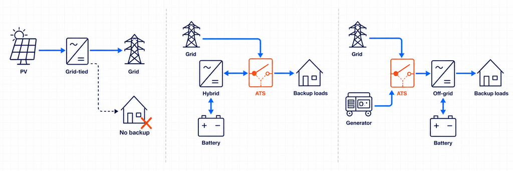
Le département de l'Énergie des États-Unis distingue les onduleurs asservis au réseau, qui nécessitent un réseau fonctionnel, des onduleurs formateurs de réseau qui peuvent fonctionner lorsque le réseau est indisponible. Il note également que les onduleurs ordinaires raccordés au réseau se déconnectent lors de perturbations plus importantes ou prolongées du réseau. C'est pourquoi un ATS ne peut pas transformer un onduleur standard raccordé au réseau en source de secours. Un secours intentionnel nécessite un onduleur et une configuration d'isolation spécifiquement conçus pour le fonctionnement en îlotage.
Architecture 1 : PV conventionnel connecté au réseau sans secours
Un onduleur PV conventionnel connecté au réseau fonctionne en parallèle avec le réseau et exporte ou compense l'énergie tant que le réseau est sain. En cas de coupure, la protection anti-îlotage déconnecte l'onduleur. Il n'y a pas de source AC alternative stable pour qu'un ATS puisse sélectionner.
Dans cette architecture, installer un ATS entre le réseau et la maison ne permet pas au système PV de continuer à fonctionner. L'onduleur a toujours besoin d'une référence réseau valide et n'est pas autorisé à alimenter un circuit isolé à moins qu'il ne soit conçu et approuvé pour former cet îlot. Si une alimentation de secours est requise, l'architecture du système doit changer : généralement en ajoutant une batterie compatible, une fonction d'onduleur formant réseau, une interface de secours et une délimitation des charges essentielles.
Architecture 2 : onduleur hybride avec dispositif de transfert interne
De nombreux onduleurs hybrides ont des bornes réseau et secours séparées. En interne, un dispositif de transfert isole le réseau et fournit une sortie de secours désignée à partir de la batterie et de l'onduleur pendant une coupure. Dans ce cas, la documentation de l'onduleur — et non un schéma générique — définit la disposition du neutre autorisée, les dispositifs de protection, la taille du tableau de secours, la séquence de reconnexion et si un ATS externe est autorisé.
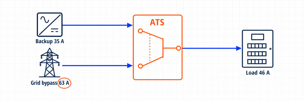
Un ATS supplémentaire peut encore avoir un objectif légitime. Par exemple, il peut contourner un onduleur défaillant et reconnecter directement le tableau de charges essentielles au réseau. Dans cette configuration, l'ATS ne crée pas l'îlotage solaire. Il sélectionne entre la sortie de secours de l'onduleur et une dérivation réseau. La valeur nominale de courant de l'ATS doit donc couvrir le courant maximal disponible sur l'un ou l'autre de ces chemins.
Certaines plateformes hybrides utilisent plutôt un contrôleur système dédié ou une interface de secours qui contient déjà la fonction de transfert. Remplacer ou dupliquer cette fonction avec un ATS polyvalent peut compromettre la surveillance du système, le contrôle du neutre, la logique anti-îlotage ou la certification du fabricant. Traitez “ commutateur de transfert interne ”, “ interface de secours ” et “ ATS de dérivation externe ” comme trois composants différents jusqu'à ce que le schéma unifilaire approuvé prouve le contraire.
Architecture 3 : Onduleur hors réseau ou formant réseau avec entrée AC alternative
Un onduleur hors réseau établit normalement la tension et la fréquence pour le bus AC local. Un réseau ou un générateur peut être connecté à une entrée AC pour que l'onduleur/chargeur puisse transférer les charges, charger la batterie ou soutenir l'alimentation. De nombreux onduleurs/chargeurs contiennent déjà un relais de transfert interne. Si la conception utilise un ATS externe, il peut sélectionner réseau versus générateur à l'entrée de l'onduleur, ou sortie onduleur versus source de dérivation au tableau de charge.
Ces deux positions ne sont pas interchangeables. Un ATS côté entrée voit le courant accepté et transmis par l'onduleur/chargeur. Un ATS de dérivation côté sortie voit le courant demandé par les charges transférées. Le contrôleur côté entrée peut également nécessiter des contacts de démarrage/arrêt du générateur, un temps de préchauffage, des fenêtres d'acceptation de tension et de fréquence, et une séquence de refroidissement. Le dispositif côté sortie doit éviter de réinjecter vers la sortie de l'onduleur lorsque la dérivation est active, sauf si la conception du fabricant le permet expressément.
Les quatre valeurs de courant que vous devez enregistrer
Une fiche de sélection fiable enregistre quatre valeurs de courant plutôt qu'un seul chiffre de puissance solaire.
Courant de conception des charges transférées
Il s'agit du courant requis par les charges connectées en aval de l'ATS. Ce n'est pas automatiquement la capacité du service principal ni automatiquement la capacité de l'onduleur. Un commutateur de transfert pour bâtiment entier peut porter la demande calculée du bâtiment. Un ATS pour charges essentielles peut ne porter que la réfrigération, l'éclairage, les commandes, les communications, les prises sélectionnées et d'autres circuits prioritaires.
Utilisez le calcul de charge du projet et le code électrique applicable. Tenez compte des charges continues, des moteurs, des transformateurs, des compresseurs et du fonctionnement simultané. Si le délestage fait partie de la conception, documentez quelles charges se déconnectent avant d'utiliser la valeur réduite.
Courant maximal de sortie de secours de l'onduleur
Lisez la fiche technique ou le manuel d'installation de l'onduleur. Privilégiez son courant de sortie de secours continu maximal déclaré plutôt qu'un calcul basé sur la puissance commerciale. Si seule la puissance apparente est disponible, les calculs AC de base sont :
Monophasé : I = S ÷ V
Triphasé : I = S ÷ (√3 × V)
Pour une sortie monophasée 10 kVA, 230 V, le courant idéal est d'environ 43,5 A. Pour une sortie triphasée 30 kVA, 400 V, il est d'environ 43,3 A par phase. Ces valeurs sont des points de départ, pas une permission d'ignorer la limite de courant du fabricant, la courbe de surcharge, la limite de déséquilibre de phase ou la correction en fonction de la température ambiante.
Courant de passage ou de dérivation du réseau
C'est fréquemment la valeur déterminante. Un onduleur hybride nominal de 8 kW de sortie de secours peut permettre à un courant de réseau plus élevé de traverser son relais interne tant que le réseau public est disponible. De même, un chemin de dérivation externe peut alimenter directement l'ensemble du tableau de charges essentielles depuis le réseau.
Si 63 A peuvent passer par l'ATS en mode réseau, sélectionner un ATS 40 A parce que l'onduleur produit seulement 8 kW est incorrect. Les contacts et les bornes de l'interrupteur supportent toujours le chemin de 63 A. Enregistrez le courant maximal d'entrée/passage AC de l'onduleur, le calibre du disjoncteur de dérivation et le calcul de charge en aval, puis utilisez la conception coordonnée la plus restrictive.
Courant maximal permis par chaque source et dispositif de protection
L'alimentation du réseau, le disjoncteur du générateur, la protection de sortie de l'onduleur, les conducteurs et le dispositif principal du tableau de distribution établissent les limites. L'ATS ne crée pas de capacité de source supplémentaire, et son calibre de courant ne protège pas les câbles à lui seul. Un commutateur de transfert de classe PC s'appuie généralement sur une protection contre les surintensités en amont coordonnée ; un agencement de classe CB intègre les fonctions de disjoncteur. Sélectionnez et vérifiez toute la chaîne de protection.
Une méthode pratique de dimensionnement de l'ATS pour les onduleurs hybrides
- Confirmez que l'onduleur peut former un îlot. S'il s'agit uniquement de PV et qu'il est connecté au réseau, arrêtez-vous : il n'y a pas de source de secours valide pour l'ATS.
- Utilisez l'architecture approuvée par le fabricant. Identifiez l'interface de secours requise, le relais de transfert interne, le commutateur externe compatible ou l'agencement de dérivation autorisé.
- Marquez la position de l'ATS. Indiquez exactement quelles deux sources se connectent à la Source I et à la Source II, et quel tableau se connecte à la sortie commune.
- Définissez les charges transférées. Utilisez un tableau des charges essentielles ou le calcul de demande de l'ensemble du bâtiment plutôt que d'additionner les plaques signalétiques des appareils sans discernement.
- Notez le courant de sortie de secours. Utilisez le courant maximal déclaré et notez séparément la capacité de surcharge de courte durée.
- Notez le courant de passage ou de dérivation du réseau. Vérifiez la limite d'entrée de l'onduleur, le calibre du relais interne, l'alimentation de dérivation et le dispositif principal du tableau.
- Sélectionnez le courant continu. L'ATS doit supporter le courant maximal crédible à sa position installée, sous réserve des règles du code, du déclassement, de la température de l'enceinte et des instructions du fabricant.
- Effectuez les vérifications hors ampérage. Vérifiez la tension, la fréquence, les phases, les pôles, le traitement du neutre, le calibre de court-circuit, la catégorie d'emploi, le temps de transfert, la détection, la tension de commande et le verrouillage.
- Validez chaque état de fonctionnement. Passez en revue le fonctionnement normal sur réseau, la panne de réseau, la défaillance de l'onduleur, la batterie déchargée, le fonctionnement du générateur, la dérivation de maintenance et le retour du réseau.
Exemple concret : onduleur hybride de 8 kW avec dérivation réseau
Considérez un système monophasé illustratif de 230 V avec ces valeurs de conception :
- Calibre de secours de l'onduleur hybride : 8 kVA en continu
- Courant maximal de sortie de secours déclaré : 35 A
- Courant de passage du réseau autorisé : 63 A
- Courant de conception du tableau de charges essentielles : 46 A lorsque le réseau est disponible
- Limite de gestion de charge en mode secours : 32 A
- Position de l'ATS externe : sortie de secours de l'onduleur contre dérivation directe du réseau
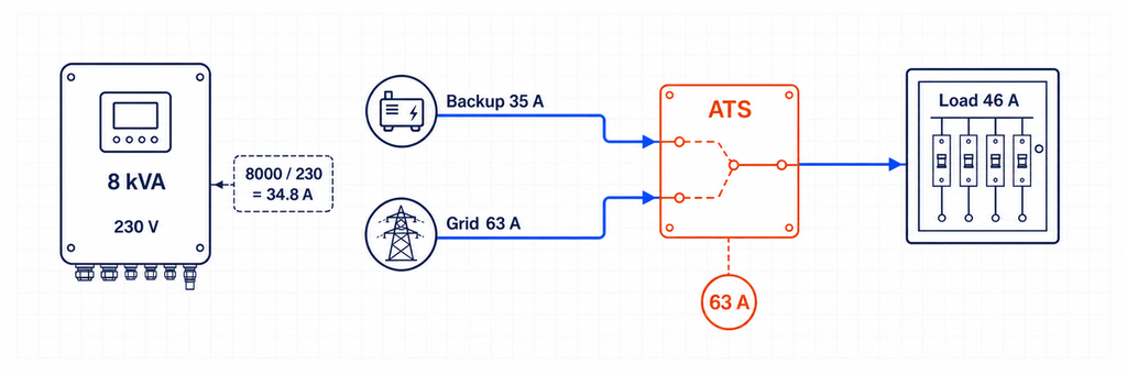
Le courant approximatif de l'onduleur à partir de la puissance apparente est 8 000 ÷ 230 = 34,8 A, cohérent avec la sortie déclarée de 35 A. Mais un ATS 40 A n'est pas automatiquement adapté. En mode dérivation réseau, le tableau des charges essentielles peut tirer 46 A et le chemin source est autorisé jusqu'à 63 A.
À cet emplacement, la sélection du courant de l'ATS est déterminée par le chemin de dérivation réseau et de charges transférées, et non par la sortie de 8 kVA de l'onduleur. Une classe de 63 A peut être la classe de courant minimale pratique si toutes les vérifications applicables de charge continue, de température, d'enceinte, de bornes et de code local le permettent. Un cadre de 80 A peut être sélectionné lorsque la conception coordonnée, le déclassement en fonction de la température ambiante, le raccordement des conducteurs ou la norme du projet exige plus de marge. La réponse finale ne peut pas être obtenue à partir de 8 kW seuls.
Le contrôleur de gestion de charge doit maintenir la demande en mode secours dans la capacité de 35 A de l'onduleur. Surdimensionner l'ATS à 63 A ou 80 A ne rend pas l'onduleur capable de fournir 46 A pendant une panne. C'est une contrainte distincte de gestion d'énergie et de puissance.
Transfert de toute la maison ou transfert des charges essentielles ?
Ce choix modifie à la fois la taille de l'ATS et le comportement du système. Un agencement de transfert de toute la maison place la limite de secours autour de la majeure partie ou de la totalité de la distribution du bâtiment. L'ATS et l'interface associée peuvent donc devoir correspondre à l'alimentation ou à la demande calculée, même lorsque l'onduleur ne peut fournir qu'une fraction de ce courant. Un secours réussi de toute la maison dépend généralement d'une gestion automatique des charges qui déconnecte le chauffage de l'eau, la climatisation de grande taille, la recharge des véhicules électriques, la cuisson électrique ou d'autres charges avant que l'onduleur ne soit surchargé.
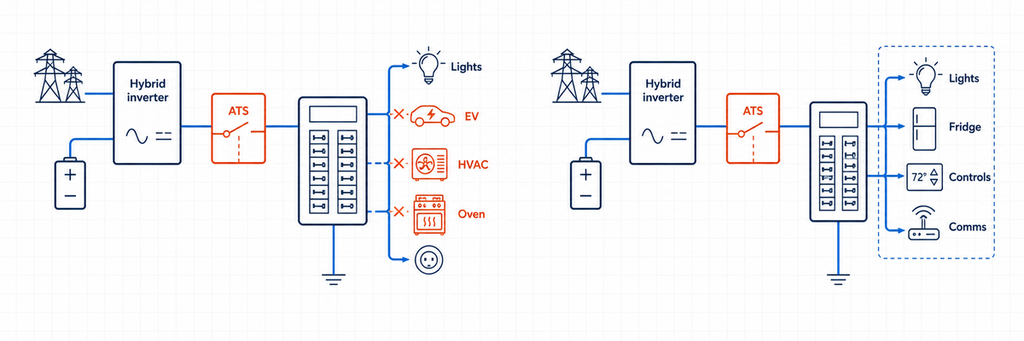
Un agencement de charges essentielles crée un tableau en aval plus petit. Seuls les circuits sélectionnés passent à l'alimentation de l'onduleur. Cela permet souvent un calibre d'ATS inférieur, des conducteurs plus petits et une autonomie de batterie plus prévisible. Cela rend également visible la limite de courant en mode secours : si le tableau contient 32 A de demande gérée, le concepteur peut le vérifier par rapport à la sortie déclarée de l'onduleur plutôt que d'espérer que les occupants éviteront les charges simultanées.
Utilisez la décision suivante :
- Choisir un panneau de charges essentielles lorsque la sortie de l'onduleur est sensiblement inférieure à la capacité de service, que l'énergie de la batterie est limitée, ou qu'une priorisation fiable des charges est plus importante que la commodité.
- Considérez le transfert de l'ensemble de la maison lorsque le contrôleur de système approuvé le prend en charge, l'onduleur et la batterie peuvent soutenir la demande prévue, et la réduction automatique de charge est documentée.
- Ne réduisez pas le courant de l'ATS simplement parce que le logiciel en mode de secours limite l'onduleur. Si les mêmes contacts supportent la demande en mode réseau complet, dimensionnez-les pour ce chemin de réseau.
Pour l'approvisionnement, indiquez les deux chiffres : “ courant continu de l'ATS à la limite installée ” et “ charge maximale autorisée en mode de secours ”. Ils répondent à des questions différentes et empêchent les installateurs de considérer un interrupteur surdimensionné comme une preuve d'une capacité d'onduleur adéquate.
Les onduleurs hybrides triphasés nécessitent des vérifications supplémentaires
Un calcul de courant triphasé suppose une puissance apparente équilibrée. Les tableaux de secours réels peuvent être déséquilibrés, et certains onduleurs hybrides imposent un courant maximal par phase ou un déséquilibre de phase maximal autorisé. Par exemple, un onduleur triphasé nominal 30 kVA, 400 V correspond à environ 43,3 A par phase :
I = 30 000 ÷ (1,732 × 400) = 43,3 A par phase
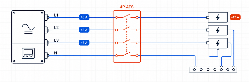
Ce résultat ne prouve pas qu'un ATS 50 A est adapté. Vérifiez si la capacité de passage réseau est de 63 A, 80 A ou une autre valeur ; si le tableau de secours peut concentrer les charges monophasées sur une phase ; et si l'onduleur peut alimenter les trois phases en mode îlot. Une charge de 4 kW ajoutée à une phase représente environ 17,4 A à 230 V même si le kVA triphasé total semble encore acceptable.
Établissez un calendrier de phase pour les charges essentielles. Gardez les grandes charges monophasées réparties autant que possible, et vérifiez la phase la plus défavorable plutôt que seulement la moyenne. Si l'onduleur permet 40 A sur chaque phase mais que le contournement du réseau permet 63 A, l'ATS à une limite de sortie de secours/contournement du réseau peut toujours nécessiter une classe de courant de 63 A. Les contrôles de charge en mode de secours doivent alors empêcher toute phase de dépasser la limite de l'onduleur.
Confirmez également ce qui se passe lorsqu'une phase échoue. Certains contrôleurs d'ATS transfèrent en cas de perte de phase ; certains onduleurs hybrides déconnectent la sortie complète ; et certaines applications nécessitent un délai spécifique pour éviter le fonctionnement sur une alimentation électrique instable. La surveillance de la séquence de phase peut être nécessaire pour les moteurs et les équipements rotatifs. La spécification du contrôleur doit indiquer le comportement en cas de sous-tension, de surtension, de perte de phase, de séquence de phase et de fréquence—pas seulement “ automatique ”.”
Ajouter un générateur à un système solaire hybride
Un générateur crée une troisième source même qu'un ATS conventionnel sélectionne normalement seulement deux. La conception nécessite donc une hiérarchie claire. Les architectures courantes incluent :
- Réseau versus générateur à l'entrée AC de l'onduleur. L'onduleur/chargeur reçoit la source AC externe sélectionnée par l'ATS d'entrée, tandis que son relais interne gère le passage et le fonctionnement batterie.
- Réseau sur l'entrée réseau de l'onduleur et générateur sur une entrée dédiée au générateur. Le contrôleur hybride gère les deux sources sans un ATS de sélection de source supplémentaire, à condition que le modèle supporte cet agencement.
- Sortie de secours de l'onduleur par rapport au contournement du générateur au panneau de charge essentielle. Cela peut préserver les charges si l'onduleur ou la batterie devient indisponible, mais la branche du générateur et la sortie de l'onduleur ne doivent jamais être mises en parallèle de manière non intentionnelle.
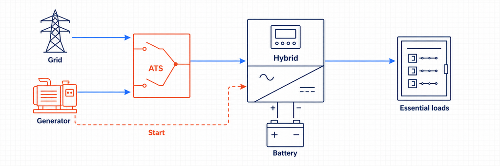
Pour un ATS réseau/générateur côté entrée, calculez le courant du générateur à partir de sa puissance kVA et comparez-le au courant AC maximal accepté par l'onduleur. Supposons qu'un générateur monophasé 15 kVA, 230 V alimente un onduleur chargeur. Son courant nominal est d'environ 65,2 A. Si l'onduleur n'accepte que 50 A, ses réglages ou protections en amont peuvent limiter la charge et le courant de passage, mais le circuit source de l'ATS doit toujours être coordonné avec le disjoncteur du générateur, les conducteurs et le chemin de charge réel. Ne supposez pas que la limite logicielle d'entrée remplace la protection du circuit.
Le fonctionnement du générateur ajoute des exigences de contrôle que les schémas uniquement solaires ne montrent pas : signal de démarrage, tentatives de démarrage, délai de préchauffage, vérification de la disponibilité de la source, temps de fonctionnement minimum, refroidissement, programme d'exercice, retour d'information sur faible carburant ou défaut, et seuils d'état de charge de la batterie. Un ATS de détection de tension de base peut transférer des charges, mais il peut ne pas coordonner la puissance de charge ou empêcher le chargeur d'onduleur de surcharger un petit générateur. Lorsque l'onduleur hybride gère le générateur, utilisez les contacts secs spécifiés et la séquence de contrôle. Si le générateur démarre mais que la charge ne se transfère pas, suivez la séquence de diagnostic de transfert de générateur ATS pour localiser le premier contrôleur ou état de chemin de puissance manquant.
Les systèmes à trois sources peuvent nécessiter deux étapes de transfert interverrouillées ou un équipement de commutation multi-sources spécialement conçu. La norme IEC 60947-6-1:2026 note les limites autour des TSE multi-sources et hybrides dans sa description de portée, donc l'assemblage complet et l'agencement du contrôleur doivent être vérifiés plutôt qu'assemblés à partir d'interrupteurs non liés et supposés conformes.
Relié au réseau contre hors réseau : Qu'est-ce qui change dans la séquence de transfert ?
Séquence de secours hybride reliée au réseau
En fonctionnement normal, le réseau établit la référence du réseau et peut alimenter les charges via le chemin de passage de l'onduleur. Lorsque la tension ou la fréquence du réseau sort de la fenêtre autorisée, le dispositif d'isolement approuvé ouvre la connexion au réseau. Ce n'est qu'après que l'isolement est confirmé que l'onduleur formant le réseau peut alimenter le bus de secours. Lorsque le réseau revient et reste stable pendant le délai configuré, le système se resynchronise ou effectue une transition ouverte selon sa logique de contrôle approuvée.
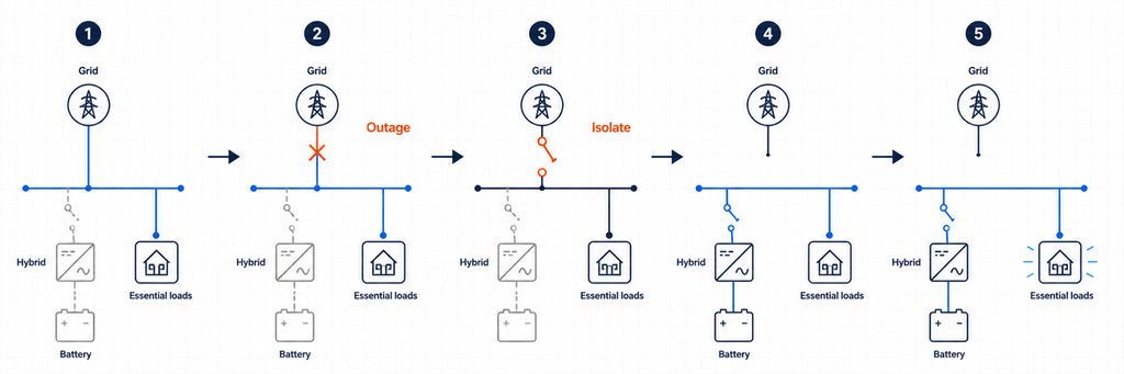
Un ATS générique qui détecte simplement “pas de tension” peut ne pas savoir si l'onduleur a terminé l'isolement, si son bus de secours est stable ou si la reconnexion est autorisée. C'est pourquoi les systèmes hybrides s'appuient souvent sur un contrôleur intégré, une interface de secours dédiée ou une coordination par contacts secs spécifiée par le fabricant de l'onduleur.
Séquence de sélection de source hors réseau
Dans une installation hors réseau, l'onduleur est normalement la source formant le réseau. L'entrée alternative du réseau ou du générateur devient acceptable uniquement après que sa tension et sa fréquence se stabilisent. Un ATS côté entrée peut choisir entre le réseau et le générateur avant d'alimenter l'onduleur/chargeur. Le relais interne de l'onduleur décide ensuite s'il doit faire passer la source acceptée ou continuer à alimenter les charges à partir de l'énergie de la batterie.
Si un deuxième ATS côté sortie fournit un contournement de maintenance, sa logique doit être coordonnée avec l'onduleur. La conception doit empêcher qu'une source de contournement soit connectée à une sortie d'onduleur sous tension, sauf si l'équipement est spécifiquement destiné à une opération parallèle synchronisée. Le verrouillage mécanique et électrique ne doit pas dépendre uniquement des commandes logicielles.
Pôles, commutation du neutre et mise à la terre
Ne choisissez pas 2P, 3P ou 4P uniquement selon une simple règle “monophasé contre triphasé”. Déterminez si le neutre doit rester solidement connecté ou être commuté, comment chaque source est mise à la terre, où se trouve la liaison neutre-terre, et comment la protection contre les courants résiduels se comporte dans chaque état de source.
Un système monophasé ligne et neutre peut utiliser un arrangement de transfert à deux pôles où les deux conducteurs doivent être commutés. Un système triphasé à quatre fils peut nécessiter un ATS à quatre pôles lorsque la source alternative crée un neutre dérivé séparément ou référencé différemment. D'autres systèmes maintiennent délibérément un neutre commun. L'arrangement correct dépend de la conception de l'onduleur, du code local, des exigences du réseau et du schéma approuvé par le fabricant.
Un traitement incorrect du neutre peut créer des chemins de neutre parallèles, des courants circulants, une protection contre les courants résiduels inefficace, des déclenchements intempestifs ou un système de secours flottant. Établissez un tableau d'état neutre et terre pour le mode réseau, le mode îlot, le mode générateur et le contournement de maintenance. Si le tableau ne montre pas une stratégie de liaison intentionnelle dans chaque état, la conception n'est pas prête pour l'installation.
La capacité de court-circuit n'est pas la même que le courant continu
Les systèmes hybrides ont deux sources de courant de défaut très différentes. Le réseau peut fournir un courant de court-circuit prospectif élevé. Un onduleur limite normalement la sortie électroniquement et peut ne fournir qu'un multiple modeste du courant nominal pendant une courte durée. L'ATS doit toujours supporter et, si nécessaire, se fermer sur la pire tenue au défaut disponible à son point d'installation.
Vérifiez le courant de défaut disponible de chaque source connectée, le dispositif de protection en amont et les données conditionnelles de court-circuit ou de tenue et fermeture du fabricant de l'ATS. Ne supposez pas que le courant de défaut limité d'un onduleur rende acceptable un petit interrupteur de transfert si les mêmes contacts sont connectés à une dérivation réseau puissante.
Pour les projets orientés IEC, IEC 60947-6-1:2026 couvre les équipements de commutation de transfert utilisés pour transférer une charge entre des sources. Pour les projets nord-américains, l'aperçu de la certification des commutateurs de l'UL identifie les catégories UL 1008 pour les commutateurs de transfert automatiques et non automatiques. Appliquez toujours l'édition et les règles d'installation adoptées par l'autorité compétente du projet.
Temps de transfert : un ATS n'est pas automatiquement un UPS
Un transfert d'ATS comprend la détection, la validation, l'opération mécanique et le temps de stabilisation. Même un commutateur rapide peut créer une interruption suffisamment longue pour réinitialiser les contrôles, les contacteurs, les équipements de communication ou les ordinateurs. Un onduleur hybride avec un relais de transfert interne peut supporter une transition plus courte qu'un ATS électromécanique séparé, mais la valeur réelle doit provenir de la documentation et des tests du système.
Classifiez les charges par tolérance de maintien. L'éclairage et la réfrigération peuvent tolérer une brève interruption. Les serveurs, les PLC, les équipements médicaux et les dispositifs réseau peuvent nécessiter un UPS ou un chemin d'onduleur sans interruption. Ne promettez pas une “alimentation ininterrompue” à partir de la capacité de courant de l'ATS.
Détails de contrôle et de détection qui déterminent s'il fonctionne
- Détection de source : Mesurez la tension et la fréquence aux bornes de la source réelle. La production PV ou l'état de charge de la batterie n'est pas la même chose qu'une source de secours AC saine.
- Retards de transfert : Empêchez le cyclage rapide pendant des conditions de réseau instables et permettez à un générateur ou à un bus d'onduleur de se stabiliser.
- Source préférée : Décidez si la sortie de secours de l'onduleur, le contournement du réseau ou le générateur est la source normale pour chaque ATS.
- Contacts secs : Confirmez les classifications de contact sans tension, la polarité logique et le comportement de sécurité avant de connecter les commandes de l'onduleur ou du générateur.
- Logique de retour : Définissez si le système revient automatiquement au réseau, attend la récupération de la batterie ou nécessite une approbation manuelle.
- Mode de défaillance : Décidez ce qui se passe si le contrôleur de l'onduleur, le moteur de l'ATS, le fusible de détection ou le lien de communication échoue.
Pour les projets nécessitant un statut à distance, sélectionnez un interrupteur de transfert automatique avec les contacts auxiliaires ou les options de communication requises. Gardez le verrouillage de source câblé indépendant de la surveillance de supervision.
Comment lire ensemble les fiches techniques de l'onduleur et de l'ATS
Le manuel de l'onduleur et la fiche technique de l'ATS utilisent des termes différents, donc créez une vérification croisée au lieu de comparer une ligne de “ courant nominal ”.
| Données de l'onduleur | Données de l'ATS à comparer | Question de conception |
|---|---|---|
| Courant de secours continu maximum | Courant opérationnel nominal et catégorie d'utilisation | Les contacts peuvent-ils supporter la sortie de l'onduleur en continu ? |
| Courant d'entrée AC maximum / courant de passage | Courant opérationnel nominal et capacité des bornes | L'ATS peut-il supporter le chemin du réseau ou du générateur plus important ? |
| Courbe de surcharge de sortie | Devoir de faire / devoir de rompre et catégorie de charge | Les événements de moteur ou de transformateur provoqueront-ils un stress de transfert ou un arrêt de l'onduleur ? |
| Fenêtres de tension/fréquence du réseau et de secours | Plage de détection du contrôleur et seuils réglables | Les deux dispositifs s'accorderont-ils sur l'acceptabilité d'une source ? |
| Temps de transfert interne | Temps de fonctionnement de l'ATS et temps de retard intentionnel | Quelle interruption la charge va-t-elle réellement subir ? |
| Schéma de neutre/terre | Arrangement de commutation 2P, 3P ou 4P | Chaque état de fonctionnement préserve-t-il le système de liaison approuvé ? |
| Contribution maximale au court-circuit | Résistance au court-circuit / classification conditionnelle | L'interrupteur est-il coordonné pour les sources d'onduleur et de réseau ? |
| Interface de contact sec ou de communication | Entrées, sorties et contacts auxiliaires du contrôleur | Les dispositifs peuvent-ils échanger en toute sécurité des statuts de permission, de défaut et de position ? |
Si une valeur est manquante, demandez-la avant de publier la spécification de l'interrupteur. “ Compatible avec le solaire ” n'est pas une classification électrique. De même, “ ATS 63 A ” ne précise pas si le dispositif est adapté à la tension, à la catégorie de charge, au niveau de défaut, à la séquence de commutation ou à la certification de marché.
Erreurs courantes de dimensionnement d'ATS pour onduleurs hybrides
Dimensionnement à partir de kW de l'array PV
Un array de 12 kWp ne signifie pas que l'ATS supporte 12 kW. La classification AC de l'onduleur, la limite de décharge de la batterie, le chemin de passage du réseau et la demande de charge transférée déterminent le courant à différents emplacements.
Utilisation uniquement de la classification de sortie de l'onduleur
Le réseau ou le générateur peut transmettre plus de courant à travers un ATS que ce que l'onduleur peut produire. C'est la raison la plus importante pour enregistrer séparément les capacités de passage et de contournement.
Dupliquer une fonction de transfert interne
Deux contrôleurs automatiques peuvent émettre des commandes contradictoires, créer des interruptions inutiles ou contourner la séquence d'isolement approuvée de l'onduleur. Utilisez une relation de contrôle maître documentée.
Supposant qu'un onduleur connecté au réseau peut fournir une sauvegarde
Le Département de l'Énergie des États-Unis explique que les onduleurs suiveurs de réseau s'éteignent lorsque l'alimentation du réseau est indisponible, tandis qu'une capacité de formation de réseau est requise pour un fonctionnement hors réseau ou de secours. Un ATS seul ne fournit pas cette capacité.
Ignorer le comportement du neutre
Une valeur de courant peut être correcte tandis que le système reste dangereux en raison d'un arrangement incorrect du neutre ou de la liaison. Examinez le fonctionnement du conducteur de protection et du courant résiduel dans chaque état de transfert.
Traiter l'ATS comme protection contre les surintensités
Un commutateur de transfert change les chemins de source. À moins que le produit sélectionné ne soit spécifiquement un arrangement de protection de classe CB, des disjoncteurs ou des fusibles coordonnés sont toujours nécessaires.
Tests de mise en service avant que le système ne soit opérationnel
- Vérifiez l'identité des conducteurs, le couple de serrage des bornes, la séquence de phases, la polarité, la continuité du neutre et les connexions de mise à la terre de protection.
- Confirmez que les noms de source de l'ATS correspondent aux sources préférées et alternatives réelles.
- Mesurez la tension et la fréquence du réseau, de l'onduleur de secours et du générateur aux points de détection.
- Simulez une panne de réseau et confirmez que l'isolement du réseau se produit avant que le bus insulaire ne soit alimenté.
- Appliquez des charges essentielles représentatives et vérifiez que le courant de secours reste dans la limite de l'onduleur.
- Désactivez ou mettez en défaut l'onduleur et vérifiez la réponse de contournement prévue sans réinjection de sa sortie.
- Rétablissez l'alimentation et confirmez le délai de retransfert, les vérifications de stabilité de la source et l'état de fonctionnement final.
- Testez les états de batterie faible, de surcharge, d'arrêt d'urgence, de fonctionnement manuel et de perte de communication.
- Enregistrez les temps de transfert, les courants, les alarmes, les réglages du contrôleur et les modifications de câblage telles que construites.
La mise en service doit être effectuée par du personnel qualifié utilisant une procédure de test approuvée. Les systèmes solaires et de batteries connectés au réseau peuvent alimenter des conducteurs depuis plusieurs directions même lorsqu'un déconnecteur est ouvert.
Liste de vérification des spécifications de l'ATS pour un projet solaire hybride
| Élément de spécification | Entrée du projet |
|---|---|
| Fonction et emplacement de l'ATS | Sélecteur de source d'entrée, contournement de sortie de secours ou isolement de service |
| Source I / Source II | Réseau, générateur, sortie de secours de l'onduleur ou combinaison approuvée |
| Courant de conception de charge transférée | À partir du calendrier de charge et des règles locales |
| Courant de secours de l'onduleur | Valeur continue maximale du fabricant |
| Courant de passage/contournement du réseau | Maximum autorisé au point installé |
| Courant opérationnel nominal | Sélectionné après vérifications de charge, de dégradation et de coordination |
| Tension, fréquence, phases | Correspondre aux deux sources et à la charge |
| Pôles et neutre | Basé sur la conception de mise à la terre approuvée |
| Données de courant de court-circuit | Courant de court-circuit disponible et dispositif de protection coordonné |
| Méthode de transfert | Transition ouverte à moins qu'une méthode synchronisée approuvée ne soit requise |
| Contrôle et retour d'information | Seuils de détection, délais, contacts secs, état, communications |
| Preuve de compatibilité | Schéma unifilaire approuvé par l'onduleur et certification applicable |
Règle de sélection finale
La taille correcte de l'ATS pour un onduleur solaire hybride est la valeur requise à la limite électrique réelle de l'interrupteur—et non le nombre imprimé à côté du système PV. D'abord, prouver que le système dispose d'une méthode de formation de réseau et d'isolement approuvée. Ensuite, comparer le courant de charge transféré, le courant de sortie de secours de l'onduleur, et le courant de passage ou de contournement du réseau. Sélectionner pour le courant crédible le plus élevé à cet endroit et terminer la conception avec des vérifications de pôle, neutre, devoir de défaut, temps de transfert, protection et contrôleur.
Pour une sélection spécifique au projet, envoyez à JUTRION le schéma unifilaire, la tension du système et les phases, le modèle de l'onduleur, le courant de sortie de secours, la valeur de passage, le calendrier de charge transférée, le courant de défaut disponible et les signaux de contrôle requis. Ces détails permettent de faire correspondre la configuration de l'ATS à l'architecture hybride ou hors réseau réelle.
Questions fréquemment posées
Ai-je besoin d'un ATS avec un onduleur solaire hybride ?
Pas toujours. De nombreux onduleurs hybrides contiennent déjà un relais de transfert interne ou fonctionnent avec une interface de secours dédiée. Un ATS externe n'est approprié que lorsque l'architecture approuvée par le fabricant nécessite des fonctions telles que la sélection d'entrée réseau ou générateur, le contournement de sortie de l'onduleur, ou la redondance de maintenance. Ajouter un autre ATS sans vérifier le schéma approuvé peut créer une logique de transfert conflictuelle.
Un ATS peut-il faire fonctionner un onduleur solaire connecté au réseau pendant une panne de courant ?
Non. Un onduleur conventionnel suivant le réseau se déconnecte lorsque le réseau électrique n'est pas disponible. Un ATS ne peut pas lui donner la capacité de formation de réseau. Le fonctionnement de secours nécessite un équipement d'îlotage compatible, un onduleur conçu pour établir un bus AC local, et généralement un stockage de batterie ou une autre source d'énergie stable.
La taille de l'ATS doit-elle correspondre à la puissance kW de l'onduleur solaire ?
Pas nécessairement. L'ATS doit être classé pour le courant maximum qui peut passer par sa position installée. Un onduleur hybride peut fournir 35 A en mode de secours tout en permettant 63 A de courant de passage du réseau. Si l'ATS transporte ce chemin de réseau, le courant crédible plus élevé — et non la puissance du panneau PV ou la puissance kW de l'onduleur seule — contrôle la classe de courant initiale.
Comment convertir la puissance kVA d'un onduleur hybride en courant ATS ?
Pour les systèmes monophasés, divisez la puissance apparente en VA par la tension : I = S ÷ V. Pour les systèmes triphasés équilibrés, utilisez I = S ÷ (√3 × V). Comparez le résultat avec le courant AC maximum déclaré de l'onduleur, car la limite de la plaque signalétique prévaut sur un calcul idéal. Ensuite, vérifiez si le courant de passage du réseau ou la demande de charge transférée est plus élevé.
L'ATS doit-il être installé avant ou après l'onduleur hybride ?
Cela dépend de son rôle prévu. Un ATS côté entrée peut sélectionner le réseau ou le générateur avant l'onduleur/chargeur. Un ATS côté sortie peut sélectionner la sortie de secours de l'onduleur ou un contournement direct du réseau pour un panneau de charge essentielle. Un dispositif de transfert de limite de service peut faire partie d'une interface de secours dédiée. Ces positions ont des exigences différentes en matière de courant, de neutre, de détection et de contrôle.
Ai-je besoin d'un ATS à 2 pôles ou à 4 pôles pour un onduleur solaire ?
Choisissez l'agencement des pôles en fonction du nombre de phases et de la conception approuvée de neutre et de mise à la terre. Certains systèmes conservent un neutre solide ; d'autres doivent commuter le neutre pour éviter des chemins parallèles ou pour accueillir une source dérivée séparément. N'appliquez pas une règle universelle “ monophasé égale 2P ” ou “ triphasé égale 4P ” sans vérifier le manuel de l'onduleur, le code local, la protection contre les courants résiduels et l'arrangement de liaison.
Puis-je utiliser un ATS plus grand que le courant de sortie de l'onduleur ?
Oui, à condition que la tension, les pôles, le devoir d'utilisation, la classification de défaut, la protection, les contrôles et la certification soient appropriés. Un ATS plus grand est souvent requis lorsque le courant de contournement du réseau dépasse le courant de secours de l'onduleur. Cependant, le commutateur plus grand n'augmente pas la sortie de l'onduleur ou la capacité de la batterie ; les charges de secours doivent toujours rester dans la limite de l'onduleur.
Un ATS est-il assez rapide pour remplacer un UPS ?
Pas automatiquement. La détection de source, la validation, le fonctionnement mécanique et la stabilisation de l'onduleur peuvent créer une interruption. Les ordinateurs sensibles, les serveurs, les contrôles, les équipements de communication ou les charges médicales peuvent encore nécessiter un UPS ou un chemin d'alimentation sans interruption vérifié. Vérifiez le temps de transfert complet du système plutôt que de vous fier à la capacité nominale de l'ATS.
Références
- IEC 60947-6-1:2026 — Équipement de commutation de transfert
- UL Solutions — Services de certification et d'évaluation des interrupteurs
- U.S. Department of Energy — Intégration solaire : Bases des onduleurs et des services de réseau
- U.S. Department of Energy — Guide solaire et conseils sur les onduleurs formant le réseau
