

How to Size an ATS for Hybrid Solar Inverters: Grid-Tied vs. Off-Grid Backup Switching Explained
To size an ATS for a hybrid solar inverter, first identify what the switch will actually transfer. Do not select it from PV-array kilowatts alone. At the installed point, compare the maximum grid pass-through current, the inverter’s maximum backup-output current, and the design current of the transferred-load panel. Use the highest current that can legitimately pass through the ATS, then verify pole arrangement, short-circuit duty, utilization category, transfer logic, and compatibility with the inverter’s approved backup architecture.
This distinction matters because “grid-tied,” “hybrid,” and “off-grid” describe different electrical behaviors. A conventional grid-following PV inverter normally stops supplying power during a sustained grid outage. A hybrid inverter may contain an internal transfer relay and a dedicated backup output. An off-grid inverter may form its own AC bus and use the grid or a generator only as an alternate input. Installing the same generic ATS in all three systems can produce nuisance trips, dead backup loads, conflicting transfer commands, or an unsafe parallel path.
This guide explains how to establish the correct ATS boundary, calculate current, and specify the switching arrangement for each architecture. It complements our general automatic transfer switch sizing guide, while focusing specifically on hybrid solar and battery-backup systems.
Quick Answer: Which Rating Should Control ATS Size?
The controlling current depends on the ATS location:
| ATS location | Sources being selected | Current basis | Common mistake |
|---|---|---|---|
| Before the inverter AC input | Grid and generator | Maximum permitted AC-input or pass-through current, transferred-load demand, and source limit | Sizing only from inverter output kW |
| After the backup output | Inverter backup output and grid bypass | Higher credible current delivered to the backup-load panel | Using PV-array kW instead of backup-panel current |
| Whole-building service boundary | Utility and intentional-island source | Service/load calculation plus approved backup-interface rating | Adding a generic ATS to a system that requires a listed backup interface |
| Off-grid AC bus | Inverter and generator or utility bypass | Maximum transferred-load current and both sources’ continuous limits | Allowing two independent controllers to connect sources without coordinated interlocking |
The selected frame size must not be lower than the maximum design current through the switch. However, amperes alone do not complete the specification. The final ATS must also suit the system voltage, number of phases, neutral and earthing arrangement, expected fault level, transfer method, and applicable installation rules.
Start with the Architecture, Not the ATS Catalog
Before calculating current, draw one line from each possible source to the loads. Mark the utility point of connection, inverter grid input, inverter backup output, battery, generator, essential-load panel, and every device capable of opening or closing a source path. If the switching mechanism, controller, source sensing, and interlocking are still unfamiliar, review how an automatic transfer switch works and how to select one before finalizing the one-line diagram. The drawing should make it impossible for the utility and an unsynchronized island source to be connected together.
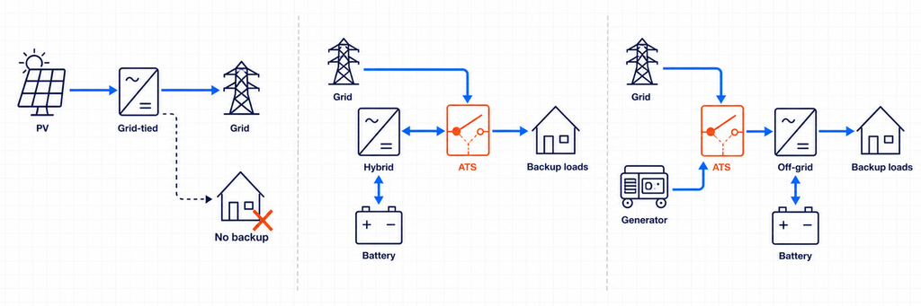
The U.S. Department of Energy distinguishes grid-following inverters, which require a functioning grid, from grid-forming inverters that can operate when the grid is unavailable. It also notes that ordinary grid-connected inverters disconnect during larger or sustained grid disturbances. That is why an ATS cannot turn a standard grid-tied inverter into a backup source. Intentional backup requires an inverter and isolation arrangement specifically designed for islanded operation.
Architecture 1: Conventional Grid-Tied PV Without Backup
A conventional grid-tied PV inverter operates in parallel with the utility and exports or offsets energy while the grid is healthy. During an outage, anti-islanding protection disconnects the inverter. There is no stable alternate AC source for an ATS to select.
In this architecture, installing an ATS between the utility and the house does not make the PV system continue operating. The inverter still needs a valid grid reference and is not permitted to energize an isolated circuit unless it is designed and approved to form that island. If outage backup is required, the system architecture must change: typically by adding a compatible battery, grid-forming inverter function, backup interface, and essential-load boundary.
Architecture 2: Hybrid Inverter with an Internal Transfer Device
Many hybrid inverters have separate grid and backup terminals. Internally, a transfer device isolates the utility and supplies a designated backup output from the battery and inverter during an outage. In this case, the inverter’s documentation—not a generic diagram—defines the permitted neutral arrangement, protective devices, backup-panel size, reconnection sequence, and whether an external ATS is allowed.
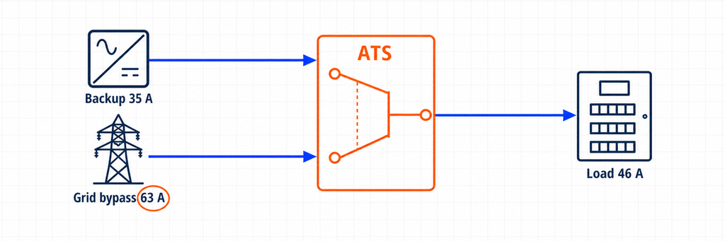
An additional ATS may still serve a legitimate purpose. For example, it can bypass a failed inverter and reconnect the essential-load panel directly to the utility. In that arrangement, the ATS is not creating the solar island. It is selecting between the inverter’s backup output and a grid bypass. The ATS current rating must therefore cover the maximum current available on either of those paths.
Some hybrid platforms instead use a dedicated system controller or backup interface that already contains the transfer function. Replacing or duplicating that function with a general-purpose ATS can defeat system monitoring, neutral control, anti-islanding logic, or manufacturer certification. Treat “internal transfer switch,” “backup interface,” and “external bypass ATS” as three different components until the approved one-line diagram proves otherwise.
Architecture 3: Off-Grid or Grid-Forming Inverter with Alternate AC Input
An off-grid inverter normally establishes voltage and frequency for the local AC bus. A utility or generator may connect to an AC input so the inverter/charger can transfer loads, charge the battery, or support power. Many inverter/chargers already contain an internal transfer relay. If the design uses an external ATS, it may select utility versus generator at the inverter input, or inverter output versus a bypass source at the load panel.
Those two positions are not interchangeable. An input-side ATS sees the current accepted and passed through by the inverter/charger. An output-side bypass ATS sees the current demanded by the transferred loads. The input-side controller may also need generator start/stop contacts, warm-up time, voltage and frequency acceptance windows, and a cool-down sequence. The output-side device must avoid back-feeding the inverter output when bypass is active unless the manufacturer’s design expressly permits it.
The Four Current Values You Must Record
A reliable selection sheet records four current values rather than one solar-power number.
1. Transferred-Load Design Current
This is the current required by the loads connected downstream of the ATS. It is not automatically the main service rating and not automatically the inverter rating. A whole-building transfer switch may carry the calculated building demand. An essential-load ATS may carry only refrigeration, lighting, controls, communications, selected receptacles, and other prioritized circuits.
Use the project load calculation and applicable electrical code. Account for continuous loads, motors, transformers, compressors, and simultaneous operation. If load shedding is part of the design, document which loads disconnect before using the reduced figure.
2. Inverter Maximum Backup-Output Current
Read the inverter datasheet or installation manual. Prefer its declared maximum continuous backup-output current over a calculation from the marketing power rating. If only apparent power is available, the basic AC calculations are:
Single phase: I = S ÷ V
Three phase: I = S ÷ (√3 × V)
For a 10 kVA, 230 V single-phase output, the ideal current is approximately 43.5 A. For a 30 kVA, 400 V three-phase output, it is approximately 43.3 A per phase. These values are starting points, not permission to ignore the manufacturer’s current limit, overload curve, phase-imbalance limit, or ambient derating.
3. Grid Pass-Through or Bypass Current
This is frequently the controlling value. A hybrid inverter rated for 8 kW of backup output may allow a larger grid current to pass through its internal relay while the utility is available. Likewise, an external bypass path may feed the entire essential-load panel directly from the grid.
If 63 A can pass through the ATS in grid mode, selecting a 40 A ATS because the inverter produces only 8 kW is incorrect. The switch contacts and terminals still carry the 63 A path. Record the inverter’s maximum AC-input/pass-through current, the bypass breaker rating, and the downstream load calculation, then use the most restrictive coordinated design.
4. Maximum Current Permitted by Each Source and Protective Device
The utility feeder, generator breaker, inverter output protection, conductors, and distribution-board main device establish boundaries. The ATS does not create extra source capacity, and its current rating does not protect cables by itself. A PC-class transfer switch commonly relies on coordinated upstream overcurrent protection; a CB-class arrangement integrates circuit-breaker functions. Select and verify the entire protective chain.
A Practical ATS Sizing Method for Hybrid Inverters
- Confirm that the inverter can form an island. If it is PV-only and grid-following, stop: there is no valid backup source for the ATS.
- Use the manufacturer’s approved architecture. Identify the required backup interface, internal transfer relay, compatible external switch, or permitted bypass arrangement.
- Mark the ATS position. State exactly which two sources connect to Source I and Source II, and which panel connects to the common output.
- Define the transferred loads. Use an essential-load schedule or the whole-building demand calculation rather than adding appliance nameplates indiscriminately.
- Record backup-output current. Use the declared maximum current and note short-duration overload capability separately.
- Record grid pass-through or bypass current. Check the inverter input limit, internal relay rating, bypass feeder, and panel main device.
- Select continuous current. The ATS must carry the maximum credible current at its installed position, subject to code rules, derating, enclosure temperature, and manufacturer instructions.
- Complete the non-ampere checks. Verify voltage, frequency, phases, poles, neutral treatment, short-circuit rating, utilization category, transfer time, sensing, control voltage, and interlocking.
- Validate every operating state. Review normal grid operation, grid failure, inverter failure, depleted battery, generator operation, maintenance bypass, and grid return.
Worked Example: 8 kW Hybrid Inverter with a Grid Bypass
Consider an illustrative 230 V single-phase system with these design values:
- Hybrid inverter backup rating: 8 kVA continuous
- Declared maximum backup-output current: 35 A
- Permitted grid pass-through current: 63 A
- Essential-load panel design current: 46 A when the grid is available
- Backup-mode load management limit: 32 A
- External ATS position: inverter backup output versus direct grid bypass
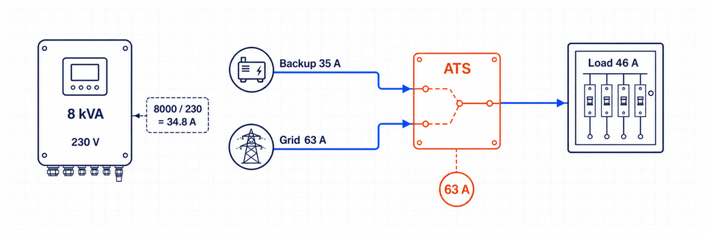
The approximate inverter current from apparent power is 8,000 ÷ 230 = 34.8 A, consistent with the declared 35 A output. But a 40 A ATS is not automatically suitable. In grid-bypass mode, the essential-load panel may draw 46 A and the source path is permitted up to 63 A.
At this location, the ATS current selection is controlled by the grid-bypass and transferred-load path, not the 8 kVA inverter output. A 63 A class may be the minimum practical current class if all applicable continuous-load, temperature, enclosure, terminal, and local-code checks permit it. An 80 A frame may be selected where the coordinated design, ambient derating, conductor termination, or project standard requires more margin. The final answer cannot be obtained from 8 kW alone.
The load-management controller must keep backup-mode demand within the inverter’s 35 A capability. Oversizing the ATS to 63 A or 80 A does not make the inverter capable of supplying 46 A during an outage. That is a separate energy and power-management constraint.
Whole-Home Transfer or Essential-Load Transfer?
This choice changes both ATS size and system behavior. A whole-home transfer arrangement places the backup boundary around most or all of the building distribution. The ATS and associated interface may therefore need to match the service or calculated demand, even when the inverter can supply only a fraction of that current. Successful whole-home backup usually depends on automatic load management that disconnects water heating, large air conditioning, EV charging, electric cooking, or other loads before the inverter is overloaded.
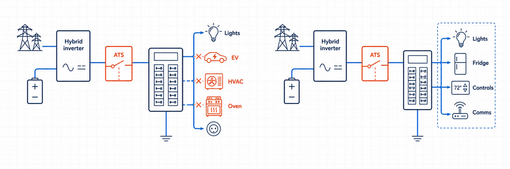
An essential-load arrangement creates a smaller downstream panel. Only the selected circuits transfer to inverter power. This often allows a lower ATS current rating, smaller conductors, and more predictable battery autonomy. It also makes the backup-mode current limit visible: if the panel contains 32 A of managed demand, the designer can verify that against the inverter’s declared output rather than hoping occupants will avoid simultaneous loads.
Use the following decision:
- Choose an essential-load panel when inverter output is materially lower than service capacity, battery energy is limited, or reliable load prioritization is more important than convenience.
- Consider whole-home transfer when the approved system controller supports it, the inverter and battery can sustain the intended demand, and automatic load shedding is documented.
- Do not reduce ATS current merely because backup-mode software limits the inverter. If the same contacts carry full grid-mode demand, size them for that grid path.
For procurement, state both numbers: “ATS continuous current at installed boundary” and “maximum permitted backup-mode load.” They answer different questions and prevent installers from treating an oversized switch as evidence of adequate inverter capacity.
Three-Phase Hybrid Inverters Need Additional Checks
A three-phase current calculation assumes balanced apparent power. Real backup panels may be unbalanced, and some hybrid inverters impose a maximum current per phase or a maximum permitted phase imbalance. For example, a nominal 30 kVA, 400 V three-phase inverter corresponds to approximately 43.3 A per phase:
I = 30,000 ÷ (1.732 × 400) = 43.3 A per phase
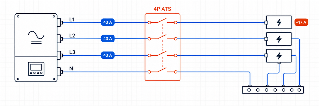
That result does not prove a 50 A ATS is suitable. Check whether the grid pass-through rating is 63 A, 80 A, or another value; whether the backup panel can concentrate single-phase loads on one phase; and whether the inverter can energize all three phases during island operation. A 4 kW load added to one phase represents roughly 17.4 A at 230 V even though total three-phase kVA still appears acceptable.
Build a phase schedule for the essential loads. Keep large single-phase loads distributed where possible, and verify the worst phase rather than only the average. If the inverter permits 40 A on each phase but the grid bypass permits 63 A, the ATS at a backup-output/grid-bypass boundary may still require a 63 A current class. Backup-mode load controls must then prevent any phase from exceeding the inverter limit.
Also confirm what happens when one phase fails. Some ATS controllers transfer on phase loss; some hybrid inverters disconnect the complete output; and some applications require a specific delay to prevent operation on unstable utility power. Phase-sequence monitoring may be necessary for motors and rotating equipment. The controller specification should state undervoltage, overvoltage, phase-loss, phase-sequence, and frequency behavior—not merely “automatic.”
Adding a Generator to a Hybrid Solar System
A generator creates a third source even though a conventional ATS normally selects only two. The design therefore needs a clear hierarchy. Common architectures include:
- Utility versus generator at the inverter AC input. The inverter/charger receives whichever external AC source the input ATS selects, while its internal relay manages pass-through and battery operation.
- Utility on the inverter grid input and generator on a dedicated generator input. The hybrid controller manages both sources without an extra source-selection ATS, provided the model supports this arrangement.
- Inverter backup output versus generator bypass at the essential-load panel. This can preserve loads if the inverter or battery becomes unavailable, but the generator branch and inverter output must never be paralleled unintentionally.
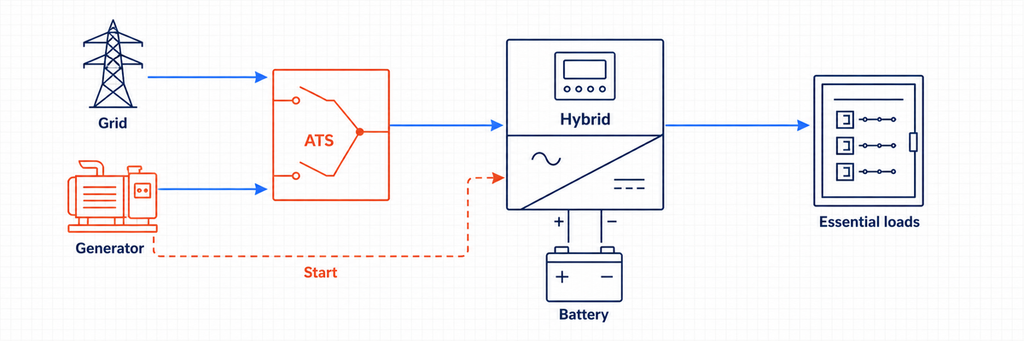
For an input-side utility/generator ATS, calculate generator current from its kVA rating and compare it with the inverter’s maximum accepted AC-input current. Suppose a 15 kVA, 230 V single-phase generator supplies an inverter charger. Its nominal current is about 65.2 A. If the inverter accepts only 50 A, its settings or upstream protection may limit charging and pass-through current, but the ATS source circuit still has to be coordinated with the generator breaker, conductors, and actual load path. Do not assume the software input limit is a substitute for circuit protection.
Generator operation adds control requirements that solar-only diagrams do not show: start signal, crank attempts, warm-up delay, source-available verification, minimum run time, cool-down, exercise schedule, low-fuel or fault feedback, and battery state-of-charge thresholds. A basic voltage-sensing ATS can transfer loads, but it may not coordinate charging power or prevent the inverter charger from overloading a small generator. Where the hybrid inverter manages the generator, use the specified dry contacts and control sequence. If the generator starts but the load does not transfer, follow the ATS generator transfer diagnostic sequence to locate the first missing controller or power-path state.
Three-source systems may require two interlocked transfer stages or purpose-built multi-source switchgear. IEC 60947-6-1:2026 notes boundaries around multi-source and hybrid TSE within its scope description, so the complete assembly and controller arrangement should be verified rather than assembled from unrelated switches and assumed to be compliant.
Grid-Tied Versus Off-Grid: What Changes in the Transfer Sequence?
Grid-Tied Hybrid Backup Sequence
In normal operation, the utility establishes the grid reference and may supply loads through the inverter’s pass-through path. When grid voltage or frequency leaves the permitted window, the approved isolation device opens the utility connection. Only after isolation is confirmed can the grid-forming inverter energize the backup bus. When the utility returns and remains stable for the configured delay, the system resynchronizes or performs an open transition according to its approved control logic.
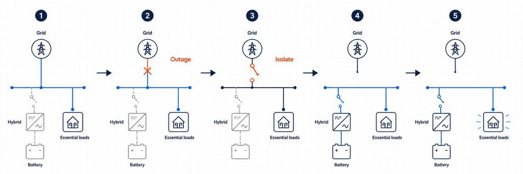
A generic ATS that merely detects “no voltage” may not know whether the inverter has completed isolation, whether its backup bus is stable, or whether reconnection is permitted. That is why hybrid systems often rely on an integrated controller, a dedicated backup interface, or dry-contact coordination specified by the inverter manufacturer.
Off-Grid Source-Selection Sequence
In an off-grid installation, the inverter is normally the grid-forming source. The alternate utility or generator input becomes acceptable only after its voltage and frequency stabilize. An input-side ATS may choose between utility and generator before feeding the inverter/charger. The inverter’s internal relay then decides whether to pass the accepted source through or continue supporting the loads from battery power.
If a second, output-side ATS provides maintenance bypass, its logic must be coordinated with the inverter. The design should prevent a bypass source from being connected to an energized inverter output unless the equipment is specifically intended for synchronized parallel operation. Mechanical and electrical interlocking should not depend on software commands alone.
Poles, Neutral Switching, and Earthing
Do not choose 2P, 3P, or 4P solely from a simple “single phase versus three phase” rule. Determine whether the neutral must remain solidly connected or be switched, how each source is earthed, where the neutral-to-earth bond exists, and how residual-current protection behaves in every source state.
A single-phase line-and-neutral system may use a two-pole transfer arrangement where both conductors must be switched. A three-phase four-wire system may require a four-pole ATS when the alternate source creates a separately derived or differently referenced neutral. Other systems deliberately keep a common neutral. The correct arrangement depends on the inverter design, local code, utility requirements, and the manufacturer’s approved diagram.
Incorrect neutral handling can create parallel neutral paths, circulating current, ineffective residual-current protection, nuisance tripping, or a floating backup system. Make a neutral-and-earth state table for utility mode, island mode, generator mode, and maintenance bypass. If the table does not show one intentional bonding strategy in each state, the design is not ready for installation.
Short-Circuit Duty Is Not the Same as Continuous Current
Hybrid systems have two very different fault-current sources. The utility can deliver a high prospective short-circuit current. An inverter normally limits output electronically and may supply only a modest multiple of rated current for a short duration. The ATS still has to withstand and, where required, close onto the worst fault duty available at its installed point.
Check the available fault current from every connected source, the upstream protective device, and the ATS manufacturer’s conditional short-circuit or withstand-and-closing data. Do not assume that an inverter’s limited fault current makes a small transfer switch acceptable if the same contacts are connected to a strong utility bypass.
For IEC-oriented projects, IEC 60947-6-1:2026 covers transfer switching equipment used to transfer a load between sources. For North American projects, UL’s switch certification overview identifies UL 1008 categories for automatic and nonautomatic transfer switches. Always apply the edition and installation rules adopted by the project’s authority having jurisdiction.
Transfer Time: An ATS Is Not Automatically a UPS
An ATS transfer includes detection, validation, mechanical operation, and stabilization time. Even a fast switch can create an interruption long enough to reset controls, contactors, communications equipment, or computers. A hybrid inverter with an internal transfer relay may support a shorter transition than a separate electromechanical ATS, but the actual value must come from the system documentation and testing.
Classify the loads by ride-through tolerance. Lighting and refrigeration may tolerate a brief interruption. Servers, PLCs, medical equipment, and network devices may require a UPS or a no-break inverter path. Do not promise “uninterrupted power” from the ATS current rating.
Control and Sensing Details That Determine Whether It Works
- Source sensing: Measure the voltage and frequency at the actual source terminals. PV production or battery state of charge is not the same as a healthy AC backup source.
- Transfer delays: Prevent rapid cycling during unstable utility conditions and allow a generator or inverter bus to stabilize.
- Preferred source: Decide whether the inverter backup output, grid bypass, or generator is the normal source for each ATS.
- Dry contacts: Confirm voltage-free contact ratings, logic polarity, and fail-safe behavior before connecting inverter or generator controls.
- Return logic: Define whether the system automatically returns to utility, waits for battery recovery, or requires manual approval.
- Failure mode: Decide what happens if the inverter controller, ATS motor, sensing fuse, or communications link fails.
For projects needing remote status, select an automatic transfer switch with the required auxiliary contacts or communications options. Keep hardwired source interlocking independent from supervisory monitoring.
How to Read Inverter and ATS Datasheets Together
The inverter manual and ATS datasheet use different terms, so create a cross-check instead of comparing one “rated current” line.
| Inverter data | ATS data to compare | Design question |
|---|---|---|
| Maximum continuous backup current | Rated operational current and utilization category | Can the contacts carry the inverter output continuously? |
| Maximum AC input/pass-through current | Rated operational current and terminal capacity | Can the ATS carry the larger grid or generator path? |
| Output overload curve | Making/breaking duty and load category | Will motor or transformer events cause transfer stress or inverter shutdown? |
| Grid and backup voltage/frequency windows | Controller sensing range and adjustable thresholds | Will both devices agree that a source is acceptable? |
| Internal transfer time | ATS operating and intentional delay time | What interruption will the load actually experience? |
| Neutral/earthing diagram | 2P, 3P, or 4P switching arrangement | Does each operating state preserve the approved bonding system? |
| Maximum fault contribution | Short-circuit withstand/conditional rating | Is the switch coordinated for both inverter and utility sources? |
| Dry-contact or communications interface | Controller inputs, outputs, and auxiliary contacts | Can the devices exchange permissive, fault, and position status safely? |
If a value is missing, request it before issuing the switch specification. “Compatible with solar” is not an electrical rating. Likewise, “63 A ATS” does not state whether the device is suitable for the voltage, load category, fault level, switching sequence, or market certification.
Common Hybrid-Inverter ATS Sizing Errors
Sizing from PV Array kW
A 12 kWp array does not mean the ATS carries 12 kW. The inverter AC rating, battery discharge limit, grid pass-through path, and transferred-load demand determine current at different locations.
Using Only the Inverter Output Rating
The grid or generator may pass more current through an ATS than the inverter can produce. This is the most important reason to record pass-through and bypass ratings separately.
Duplicating an Internal Transfer Function
Two automatic controllers can issue contradictory commands, create unnecessary interruptions, or bypass the inverter’s approved isolation sequence. Use a documented master-control relationship.
Assuming Any Grid-Tied Inverter Can Provide Backup
The U.S. Department of Energy explains that grid-following inverters shut down when grid power is unavailable, while grid-forming capability is required for off-grid or backup operation. An ATS alone does not supply that capability.
Ignoring Neutral Behavior
A current rating can be correct while the system remains unsafe because of an incorrect neutral or bonding arrangement. Review protective-conductor and residual-current operation in every transfer state.
Treating the ATS as Overcurrent Protection
A transfer switch changes source paths. Unless the selected product is specifically a CB-class protective arrangement, coordinated breakers or fuses are still required.
Commissioning Tests Before the System Goes Live
- Verify conductor identity, terminal torque, phase sequence, polarity, neutral continuity, and protective-earthing connections.
- Confirm the ATS source names match the actual preferred and alternate sources.
- Measure grid, inverter-backup, and generator voltage and frequency at the sensing points.
- Simulate a grid failure and confirm utility isolation occurs before the island bus is energized.
- Apply representative essential loads and verify backup current remains within the inverter limit.
- Disable or fault the inverter and verify the intended bypass response without back-feeding its output.
- Restore the utility and confirm the retransfer delay, source stability checks, and final operating state.
- Test battery-low, overload, emergency-stop, manual operation, and communications-loss states.
- Record transfer times, currents, alarms, controller settings, and as-built wiring changes.
Commissioning must be performed by qualified personnel using an approved test procedure. Utility-connected solar and battery systems can energize conductors from multiple directions even when one disconnect is open.
ATS Specification Checklist for a Hybrid Solar Project
| Specification item | Project entry |
|---|---|
| ATS function and location | Input source selector, backup-output bypass, or service isolation |
| Source I / Source II | Utility, generator, inverter backup output, or approved combination |
| Transferred-load design current | From the load schedule and local rules |
| Inverter backup current | Manufacturer’s maximum continuous value |
| Grid pass-through/bypass current | Maximum permitted at the installed point |
| Rated operational current | Selected after load, derating, and coordination checks |
| Voltage, frequency, phases | Match both sources and load |
| Poles and neutral | Based on the approved earthing design |
| Fault-duty data | Available fault current and coordinated protective device |
| Transfer method | Open transition unless an approved synchronized method is required |
| Control and feedback | Sensing thresholds, delays, dry contacts, status, communications |
| Compatibility evidence | Inverter-approved one-line diagram and applicable certification |
Final Selection Rule
The correct ATS size for a hybrid solar inverter is the rating required at the switch’s real electrical boundary—not the number printed beside the PV array. First prove that the system has an approved grid-forming and isolation method. Then compare transferred-load current, inverter backup-output current, and grid pass-through or bypass current. Select for the highest credible current through that location and finish the design with pole, neutral, fault-duty, transfer-time, protection, and controller checks.
For a project-specific selection, send JUTRION the one-line diagram, system voltage and phases, inverter model, backup-output current, pass-through rating, transferred-load schedule, available fault current, and required control signals. Those details allow the ATS configuration to be matched to the actual hybrid or off-grid architecture.
Frequently Asked Questions
Do I need an ATS with a hybrid solar inverter?
Not always. Many hybrid inverters already contain an internal transfer relay or work with a dedicated backup interface. An external ATS is appropriate only when the manufacturer’s approved architecture calls for functions such as grid-versus-generator input selection, inverter-output bypass, or maintenance redundancy. Adding another ATS without checking the approved diagram can create conflicting transfer logic.
Can an ATS make a grid-tied solar inverter work during a power outage?
No. A conventional grid-following inverter disconnects when the utility grid is unavailable. An ATS cannot give it grid-forming capability. Backup operation requires compatible islanding equipment, an inverter designed to establish a local AC bus, and usually battery storage or another stable energy source.
Should ATS size match the solar inverter kW rating?
Not necessarily. The ATS must be rated for the maximum current that can pass through its installed position. A hybrid inverter may provide 35 A in backup mode while permitting 63 A of grid pass-through current. If the ATS carries that grid path, the larger credible current—not PV-array power or inverter kW alone—controls the initial current class.
How do I convert hybrid inverter kVA to ATS current?
For single-phase systems, divide apparent power in VA by voltage: I = S ÷ V. For balanced three-phase systems, use I = S ÷ (√3 × V). Compare the result with the inverter’s declared maximum AC current, because the nameplate limit takes precedence over an ideal calculation. Then check whether grid pass-through current or transferred-load demand is higher.
Should the ATS be installed before or after the hybrid inverter?
It depends on its intended job. An input-side ATS may select utility or generator before the inverter/charger. An output-side ATS may select inverter backup output or a direct grid bypass for an essential-load panel. A service-boundary transfer device may be part of a dedicated backup interface. These positions have different current, neutral, sensing, and control requirements.
Do I need a 2-pole or 4-pole ATS for a solar inverter?
Choose the pole arrangement from the number of phases and the approved neutral-and-earthing design. Some systems retain a solid neutral; others must switch the neutral to avoid parallel paths or to accommodate a separately derived source. Do not apply a universal “single phase equals 2P” or “three phase equals 4P” rule without checking the inverter manual, local code, residual-current protection, and bonding arrangement.
Can I use a larger ATS than the inverter output current?
Yes, provided the voltage, poles, utilization duty, fault rating, protection, controls, and certification are suitable. A larger ATS is commonly required when grid bypass current exceeds inverter backup current. However, the larger switch does not increase inverter output or battery capacity; backup loads must still remain within the inverter’s limit.
Is an ATS fast enough to replace a UPS?
Not automatically. Source detection, validation, mechanical operation, and inverter stabilization can create an interruption. Sensitive computers, servers, controls, communications equipment, or medical loads may still need a UPS or a verified no-break power path. Check the complete system transfer time rather than relying on the ATS current rating.
References
