

¿Qué tamaño de caja combinadora solar necesito? Conteo de cadenas, fusible, corriente y dimensionamiento de voltaje.
Respuesta rápida: ¿Qué tamaño de caja combinadora solar necesita?
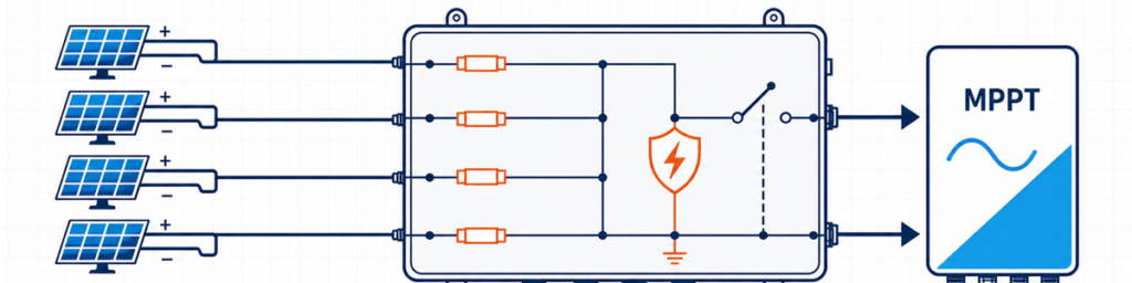
Cuatro cadenas PV conectadas a través de una caja combinadora solar con fusible a una entrada MPPT de inversorUna caja combinadora solar debe coincidir con el número de cadenas PV compatibles que alimentan una entrada del inversor, el voltaje máximo de circuito abierto en frío del conjunto, la corriente de diseño combinada basada en Isc y la protección requerida en esa ubicación. Solo el conteo de entradas no es suficiente. Cuatro cadenas pueden necesitar una caja 4-in/1-out, dos circuitos separados 2-in/1-out o ninguna caja combinadora externa, dependiendo del inversor y la disposición del cableado.
Para un comprador, “4 cadenas, 1000 V” suena como una especificación utilizable. Para el ingeniero que revisa la cotización, es solo el comienzo. La hoja de datos del módulo puede mostrar que la cadena se acerca a 1000 V en una mañana fría. El inversor puede asignar las cadenas a dos MPPT independientes. La ruta de salida puede necesitar transportar casi 70 A después de aplicar el factor de corriente del proyecto. Cualquiera de esos hechos puede cambiar la caja.
El objetivo aquí es convertir la información ya presente en la hoja de datos del módulo, el programa del inversor y el diagrama unifilar en una especificación preliminar defendible. Para configuraciones generales y opciones de productos disponibles, consulte la Gama de cajas combinadoras PV de JUTRION.
Comience con el dibujo del inversor, no con el número de cadenas en el techo
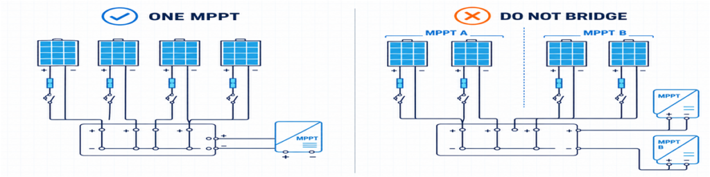
Agrupación correcta de cadenas PV para un MPPT comparada con la conexión incorrecta de entradas MPPT separadasLas cadenas que entran en una salida de la caja combinadora deben tener un destino válido. Eso suena obvio, pero es donde muchas cotizaciones tempranas salen mal.
Suponga que un techo tiene ocho cadenas. El dibujo del inversor asigna cuatro al MPPT A y cuatro al MPPT B. Solicitar una caja combinadora de 8 entradas/1 salida uniría dos circuitos que el inversor fue diseñado para controlar de forma independiente. Las opciones viables normalmente son dos grupos separados de 4 entradas/1 salida, un gabinete que contenga dos secciones eléctricamente independientes, o conexiones directas de cadenas si el inversor ya proporciona entradas y protección adecuadas.
Las cadenas destinadas a operar en paralelo también deben ser genuinamente compatibles. Verifique el tipo de módulo, los módulos por cadena, la orientación y el sombreado esperado. Las longitudes de cadena desiguales tienen voltajes de operación diferentes. Combinar cadenas muy sombreadas y sin sombrear también puede producir un mal acoplamiento operativo incluso cuando las etiquetas de los módulos son idénticas.
Esto da la primera regla utilizable:
Cuente las cadenas asignadas a una ruta MPPT compatible, no todas las cadenas visibles en el dibujo del proyecto.
Cuándo una caja combinadora externa aporta poco valor
Muchos inversores string ya proporcionan múltiples entradas DC, protección interna contra sobretensiones y una función de aislamiento DC. Si cada cadena puede conectarse directamente a una entrada adecuada del inversor, añadir una combinadora externa puede crear terminaciones de cable adicionales sin resolver un problema de diseño.
Una caja de una sola cadena es un caso relacionado pero diferente. Una unidad de 1 entrada/1 salida no combina corriente; actúa como una caja externa de protección y aislamiento. Eso puede ser útil cuando el inversor está remoto, se requiere un punto de aislamiento local o el proyecto quiere protección contra sobretensiones reemplazable en una ubicación accesible.
Los cinco números que vale la pena poner en una sola hoja
Antes de mirar los tamaños de los fusibles o las dimensiones del gabinete, recopile cinco grupos de información. La mayoría se puede copiar directamente de los documentos emitidos del proyecto.
| Información | De dónde proviene normalmente | Qué cambia |
|---|---|---|
| Voc, Isc, Imp, coeficiente de temperatura y fusible máximo en serie | Ficha técnica del módulo PV | Límites de voltaje, corriente y fusible de cadena |
| Módulos por cadena y número de cadenas en paralelo | Programa de cadenas | Número de entradas y voltaje/corriente totales |
| Disposición del MPPT y límites de entrada | Hoja de datos del inversor y diagrama unifilar | Qué cadenas pueden compartir una salida |
| Temperatura mínima, montaje y exposición | Base de diseño del proyecto y datos del sitio | Voc en frío, reducción de capacidad y envolvente |
| País de destino y normas aplicables | Especificación del proyecto | Método de protección y documentación |
Un valor que a menudo se pasa por alto es la corriente máxima permisible de cortocircuito del inversor. La corriente máxima de operación y la corriente máxima de cortocircuito no son intercambiables. Un conjunto propuesto debe verificarse contra ambos.
El país de destino importa tanto como los datos eléctricos. Un cálculo de fusibles preparado para un proyecto orientado a IEC no debe tomar silenciosamente un multiplicador norteamericano y presentarlo como una regla universal.
Verifique el voltaje de la cadena en frío antes de elegir 1000 V o 1500 V
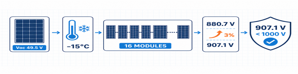
Cálculo del Voc de cadena PV en clima frío para 16 módulos resultando en un voltaje de diseño de 907,1 VEl Voc del módulo normalmente se indica en condiciones de prueba estándar. Aumenta a medida que baja la temperatura de la celda, por lo que la condición más fría esperada controla el voltaje máximo de la cadena.
Cuando la hoja de datos del módulo indica un coeficiente de temperatura negativo de Voc como porcentaje por grado Celsius, un cálculo inicial es:
Voc,frío = Voc,STC × [1 + |βVoc| × (25 − Tmín)]
Vcadena,frío = Voc,frío × número de módulos en serie
Introduzca el coeficiente como decimal. Por ejemplo, −0,28 %/°C se convierte en -0,0028 en la fórmula. Si el fabricante del módulo proporciona un método diferente para bajas temperaturas, utilice ese método en su lugar.
La respuesta debe acomodar más que el inversor. El portafusibles y el fusible, SPD, interruptor-seccionador o interruptor automático, terminales, conductores y el conjunto completo están en el mismo circuito DC. Reemplazar solo el SPD con un dispositivo de 1500 V no convierte una caja de 1000 V en un conjunto de 1500 V.
Un pequeño margen de tensión no utilizado no es capacidad desperdiciada. Absorbe la base de temperatura específica del proyecto y las tolerancias que realmente se han identificado. Lo que debe evitarse es un margen aleatorio sin una fuente registrada.
Los fusibles de cadena dependen de la corriente inversa, no de la costumbre
Cuando las cadenas en paralelo están sanas, cada una aporta corriente a la salida común. Si una cadena desarrolla una falla, las demás pueden devolver corriente hacia ella. El fusible de cadena está ahí para interrumpir esa corriente inversa dañina donde se requiere protección.
Una evaluación inicial de la contribución de las otras cadenas es:
Iinversa,evaluación = (n − 1) × Isc,cadena
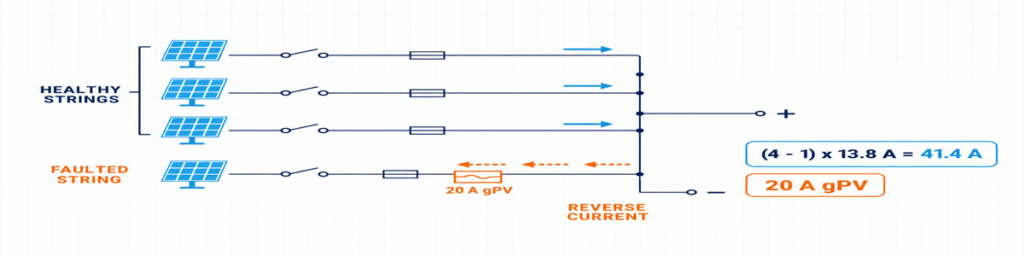
Corriente inversa de tres cadenas PV sanas hacia una cadena con fallo protegida por un fusible gPV de 20 AAquí, n es el número de cadenas en paralelo. La expresión muestra por qué la respuesta cambia rápidamente entre dos y cuatro entradas: una cadena con falla en un grupo de cuatro cadenas puede recibir corriente de tres cadenas sanas.
No trate esa expresión como el diseño final de protección. El fusible gPV seleccionado debe soportar la corriente esperada bajo las condiciones reales del recinto, proteger el cable y el equipo, mantenerse dentro de la clasificación máxima de fusible en serie del módulo y tener capacidad adecuada de tensión y ruptura en DC PV. El portafusibles y el fusible se verifican juntos, incluyendo efectos de temperatura y agrupamiento.
IEC 60269-6 cubre requisitos suplementarios para fusibles usados en cadenas y arreglos fotovoltaicos hasta 1500 V DC. Las normas de instalación adoptadas para el proyecto determinan cómo se aplica ese producto.
Sobre la cifra de 1,56 × Isc que se ve en línea
La conocida cifra 1,56 × Isc está asociada con dos factores del 125 % usados en caminos comunes de diseño en Norteamérica. No debe ser etiquetada como una fórmula universal IEC. Si el proyecto está regido por el NEC, use la edición adoptada, las certificaciones de equipo y los requisitos locales. Si es un proyecto IEC, aplique las reglas de instalación basadas en IEC y las instrucciones de los fabricantes de módulos, fusibles y cables.
Vale la pena indicar esta distinción en la cotización. De lo contrario, dos proveedores pueden devolver tamaños de fusible diferentes aunque ambos hayan recibido los mismos datos del conjunto.
Dimensionar la ruta combinada por separado de cada entrada
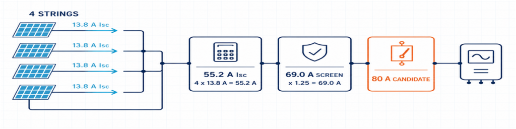
Cuatro cadenas PV de 13,8 A combinadas a 55,2 A Isc con una pantalla de diseño de 69 A y un candidato a dispositivo de salida de 80 ALos lados de entrada y salida conducen corrientes diferentes. Cada entrada conduce una cadena; la salida común conduce la suma de las cadenas en paralelo.
Isc,total = número de cadenas en paralelo × Isc,cadena
Luego se aplican el factor de diseño requerido del proyecto y los factores de corrección a los conductores y equipos apropiados. El resultado afecta el cableado interno, barras colectoras, bornes, el cable de salida y el dispositivo de conmutación de salida. También debe compararse con los límites declarados del inversor.
Usar solo Imp para toda la selección puede dejar la ruta de protección demasiado pequeña. Usar solo Isc sin verificar la corriente normal MPPT del inversor puede pasar por alto una limitación operativa. Mantenga los valores separados y asigne a cada uno un propósito.
| Valor | Úselo para verificar |
|---|---|
| Imp de la cadena | Corriente de funcionamiento normal y compatibilidad con el MPPT del inversor |
| Isc de la cadena | Corriente de diseño de la cadena y cálculos de protección contra sobrecorriente |
| Isc total | Ruta combinada y límite de corriente de cortocircuito del inversor |
| Corriente de diseño del proyecto corregida | Conductores, barras colectoras, terminales y dispositivo de salida en condiciones instaladas |
El calor puede anular una clasificación de catálogo aparentemente cómoda. Los portafusibles estrechamente agrupados, las pérdidas en los terminales, el SPD y la radiación solar directa contribuyen a la temperatura del gabinete. Un dispositivo de 80 A en una condición de referencia no es automáticamente una solución de 80 A dentro de cualquier caja exterior.
Los fusibles, aislamiento, interruptores y SPDs tienen funciones diferentes
Una caja combinadora es más fácil de especificar cuando cada componente tiene una función clara:
- Fusible gPV: protege una cadena individual contra la condición de sobrecorriente inversa aplicable;
- seccionador con interruptor: proporciona conmutación de carga DC PV y un punto de aislamiento definido;
- Interruptor automático DC: conmuta el circuito y proporciona función de sobrecorriente cuando sus características y clasificaciones de interrupción DC son adecuadas para la aplicación;
- SPD DC PV: limita la sobretensión transitoria y no reemplaza la protección contra sobrecorriente ni el aislamiento.
Un interruptor de salida no es obligatorio simplemente porque haya espacio para uno. El diseño del sistema puede requerir un seccionador con interruptor cuando la protección contra sobrecorriente ya esté prevista en otro lugar, o un interruptor automático con una función de protección definida. Decida primero la función.
El mismo principio se aplica al SPD. Confirme la aplicación PV DC, UCPV, los modos de protección, el nivel de protección, la corriente de descarga asignada, el comportamiento ante cortocircuitos y la coordinación de respaldo. El tipo 2 se usa comúnmente para condiciones de sobretensión inducida. Cuando exista un sistema externo de protección contra rayos u otra ruta de corriente de rayo, la disposición puede requerir protección de tipo 1 o tipo 1+2. Consulte la Gama JUTRION PV DC SPD después de conocer el voltaje del proyecto y el contexto de rayos.
Para la función de aislamiento, un dispositivo clasificado para la función PV prevista es más significativo que una descripción genérica de “interruptor DC”. El gama de aisladores JUTRION PV DC incluye opciones DC-PV2 para revisar según el voltaje, corriente y disposición de polos requeridos.
Un ejemplo de cuatro cadenas desde la hoja de datos hasta la caja
Ejemplo ilustrativo: Este es un caso comercial construido en azotea utilizado para mostrar el cálculo. No es un proyecto de cliente ni un diseño universal.
Cuatro cadenas idénticas están asignadas a una entrada de inversor de alta corriente. Cada cadena contiene 16 módulos. La hoja de datos del módulo indica Voc = 49,5 V, Isc = 13,8 A, βVoc = −0,28%/°C y una clasificación máxima de fusible en serie de 25 A. La temperatura mínima del proyecto es −15°C. Su base de diseño también aplica una tolerancia declarada del 3% después del cálculo de temperatura.
El inversor ilustrativo tiene una entrada máxima DC de 1000 V, una corriente máxima de entrada de 80 A y una corriente máxima de cortocircuito de 100 A. No se asume sistema externo de protección contra rayos.
El diagrama señala cuatro entradas y una salida
Las cuatro cadenas usan los mismos módulos y longitud de cadena, y la documentación del inversor permite que alimenten la misma entrada. Por lo tanto, una arquitectura 4 entradas/1 salida es apropiada en esta etapa. Si el diagrama las dividiera entre dos MPPT, la respuesta sería dos grupos independientes de 2 entradas/1 salida.
La cadena fría alcanza 907,1 V
Módulo en frío Voc = 49,5 × [1 + 0.0028 × (25 − (−15))] = 55,04 V
Voc cadena fría = 55,04 × 16 = 880,7 V
Voltaje de diseño del proyecto = 880,7 × 1,03 = 907,1 V
Un montaje verificado de 1000 V puede pasar esta comprobación preliminar, al igual que el inversor ilustrativo. El margen restante es de aproximadamente 93 V. Un decimoséptimo módulo elevaría el resultado a aproximadamente 964 V antes de la misma tolerancia y no pasaría este ejemplo tras aplicar la tolerancia.
Las cadenas en paralelo hacen necesaria la fusión individual
Las otras tres cadenas pueden contribuir con una corriente inversa inicial de:
(4 − 1) × 13.8 = 41.4 A
Eso está por encima de la clasificación máxima de fusible en serie de 25 A del módulo, por lo que se requiere protección individual de cadena en este ejemplo. El método del proyecto produce una pantalla preliminar de corriente de fusible inferior de 1,25 × 13,8 = 17,25 A. Un fusible gPV de 20 A está entre ese valor y el límite de 25 A del módulo. Antes de aceptarlo, deben verificarse su portafusibles, protección del cable, temperatura del recinto y capacidad de corriente continua.
La salida común necesita más que una etiqueta de 55,2 A
La corriente combinada de cortocircuito es:
4 × 13.8 = 55.2 A
La base de diseño del ejemplo usa 1,25 × Isc como pantalla preliminar de corriente de salida:
1.25 × 55.2 = 69.0 A
Un interruptor-desconectador DC PV de 80 A es un marco de partida razonable, no una elección final automática. La clasificación térmica instalada, el voltaje, los polos y el deber de conmutación deben verificarse. El límite de cortocircuito de 100 A del inversor supera la comparación de 55,2 A. Su límite operativo de 80 A debe compararse con cuatro veces el Imp del módulo según la hoja de datos real.
La caja preliminar ahora es lo suficientemente específica para revisar: cuatro entradas con fusibles independientes, una salida combinada, componentes de clase 1000 V en todo, un camino combinado diseñado alrededor de la pantalla declarada de 69 A, aislamiento PV DC y un SPD PV DC Tipo 2 sujeto a coordinación final.
El resultado en una página
El cálculo es más fácil de revisar cuando las suposiciones, el resultado y la comprobación restante se mantienen juntos. Este también es el punto donde un comprador puede ver si dos cotizaciones se basan realmente en la misma función.
| Elemento de selección | Resultado ilustrativo | Lo que aún necesita confirmación |
|---|---|---|
| Configuración | 4 entradas / 1 salida | Las cuatro cadenas alimentan una entrada compatible del inversor |
| Voltaje máximo del proyecto | 907.1 V | Base de temperatura del sitio, método de tolerancia y límite del inversor |
| Protección de cadena | Selección preliminar de 20 A gPV | Temperatura del portafusibles, protección del cable y normas aplicables |
| Corriente combinada de cortocircuito | 55.2 A | Corriente máxima permisible de cortocircuito del inversor |
| Pantalla preliminar de corriente de salida | 69.0 A | Factores de corrección y temperatura de montaje instalada |
| Aislamiento de salida | El bastidor de 80 A es un candidato inicial | Deber, polos, tensión y corriente nominal instalada de PV DC |
| Protección contra sobretensiones | SPD tipo 2 para PV DC inicialmente | Ucpv, modos de protección, LPS y coordinación de respaldo |
| Envolvente | Mínimo IP65 para exteriores | UV, corrosión, calor, prensaestopas y condensación |
Elección entre una configuración 1/1, 2/1 y 4/1
JUTRION actualmente muestra productos de 1000 V DC, IP65 en configuraciones 1-in/1-out, 2-in/1-out y 4-in/1-out. Use el número de entradas para preseleccionar la arquitectura y luego confirme las características nominales que produjo el cálculo del proyecto.
| Configuración | Razón típica para preseleccionarlo | Razón para detenerse y reconsiderar |
|---|---|---|
| 1 entrada / 1 salida | Una cadena necesita un punto accesible de protección y aislamiento | No ocurre combinación; verifique que una caja separada añada una función requerida |
| 2 entradas / 1 salida | Dos cadenas emparejadas alimentan una entrada de inversor | Las cadenas pertenecen a MPPTs separados o exceden los límites combinados de entrada |
| 4 entradas / 1 salida | Cuatro cadenas emparejadas alimentan una entrada de alta corriente con la clasificación adecuada | El inversor necesita dos grupos MPPT o la ruta de salida está subdimensionada |
El ejemplo trabajado apunta hacia una arquitectura JUPV1000-4/1. No aprueba el fusible interno, dispositivo de salida o SPD solo por el nombre del modelo. Esos componentes deben cotizarse según el voltaje del proyecto de 907,1 V, la protección de cadena gPV de 20 A propuesta, la pantalla preliminar de corriente combinada de 69 A y las condiciones de instalación exterior.
Las configuraciones personalizadas de cadenas de 1500 V o mayores merecen una revisión fresca de componentes y montaje. No deben tratarse como un cambio de etiqueta al arreglo estándar de 1000 V.
La caja para exteriores puede cambiar la clasificación de corriente
Los cálculos eléctricos a menudo se completan en una oficina a 25 °C. La caja puede pasar su vida útil en un tejado donde el aire es mucho más caliente, la luz solar directa calienta el armario y varios portafusibles llevan corriente lado a lado. Esa diferencia afecta más que la comodidad durante el mantenimiento.
El calor se produce en fusibles, bornes, conductores, el SPD y el dispositivo de salida. Los componentes muy juntos tienen menos oportunidad de enfriarse, mientras que un armario sellado restringe el intercambio de aire. Un componente que soporta su corriente marcada bajo condiciones de referencia puede requerir reducción de carga en el montaje final. Por eso el interruptor-seccionador de 80 A en el ejemplo sigue siendo un bastidor inicial hasta que se revise el arreglo instalado.
IP65 es útil, pero solo responde a una cuestión de protección contra la penetración. No establece automáticamente:
- resistencia a la exposición ultravioleta a largo plazo;
- rendimiento frente a la corrosión cerca de la costa o en una atmósfera industrial;
- temperatura interna aceptable bajo corriente plena y calentamiento solar;
- control de condensación durante el calentamiento y enfriamiento diario;
- idoneidad de las prensaestopas, sellos y materiales para los cables instalados;
- rendimiento del aislamiento a gran altitud.
Los detalles de montaje también importan. Las entradas de cable realizadas a través de la parte superior de un armario exterior crean un camino de agua diferente al de la entrada inferior. Las prensaestopas de tamaño insuficiente pueden dañar los sellos o dejar un soporte insuficiente para el cable. Las curvas cerradas del cable pueden transferir fuerza mecánica a los portafusibles y terminales. El armario debe revisarse como un conjunto instalado, no como una caja vacía de plástico o metal con un número IP.
IEC 61439-2:2020 Cubre conjuntos de cuadros eléctricos de potencia y control hasta 1500 V DC. La relevancia aquí es práctica: usar componentes con clasificación individual no elimina la necesidad de verificar el conjunto completo, incluyendo el aumento de temperatura, propiedades dieléctricas, circuitos de protección, distancias de seguridad, cableado y construcción mecánica según corresponda.
Envíe suficiente información para que el proveedor pueda verificar el resultado
Una consulta técnica breve es más útil que un extenso formulario de compra. Adjunte las hojas de datos del módulo e inversor y especifique:
- cadenas por salida y módulos por cadena;
- Voc, Isc, Imp, βVoc del módulo y fusible máximo en serie;
- temperatura mínima de diseño y cualquier margen de tensión;
- configuración MPPT del inversor y límites de entrada;
- tensión máxima calculada y corriente combinada de diseño;
- funciones requeridas de fusible, aislamiento, interruptor y SPD;
- ubicación del armario, requisito IP, ambiente, exposición a UV y corrosión;
- tamaños de cable, monitorización, mercado destino y cantidad.
Para el proyecto ilustrativo, eso se traduce en: 4 entradas/1 salida, cuatro cadenas idénticas de 16 módulos alimentando un MPPT, 907,1 V tensión de diseño declarada, fusibles gPV preliminares de 20 A, Isc total de 55,2 A, valor preliminar de corriente de salida de 69 A, aislamiento PV DC, protección contra sobretensiones PV DC Tipo 2 coordinada y un armario para exteriores.
Por qué dos presupuestos “4 cadenas, 1000 V, IP65” pueden no ser equivalentes
Un presupuesto puede usar portafusibles y fusibles gPV verificados para la tensión y temperatura previstas. Otro puede listar solo una corriente nominal del fusible. Una caja puede incluir un interruptor seccionador con carga; otra puede usar un dispositivo destinado principalmente al aislamiento. El SPD Ucpv, modos de protección, comportamiento ante cortocircuito y posibilidad de reemplazo también pueden diferir aunque ambos presupuestos indiquen “SPD Tipo 2.”
La salida común es otra fuente de diferencias ocultas. Compare la capacidad de corriente instalada de las barras colectoras, conductores, terminales y dispositivo de salida, no solo el número de amperios más grande impreso en la lista de materiales. También verifique la capacidad del terminal frente al cable saliente real. Un presupuesto técnicamente más barato no es más económico si requiere sustitución de prensaestopas, un armario mayor o retrabajo en obra.
Por tanto, una comparación útil normaliza los siguientes elementos antes del precio:
- configuración entrada/salida y agrupación MPPT;
- tensión máxima DC del camino completo;
- clase, clasificación y límite de módulo del fusible de cadena;
- corriente combinada y condiciones de temperatura instaladas;
- función del dispositivo de salida y servicio en DC;
- tipo de SPD, Ucpv, modos y coordinación;
- capacidad de bornas y prensaestopas;
- material del envolvente y adecuación ambiental.
La selección final debe leerse como un camino eléctrico conectado. Si el presupuesto solo confirma el número de entradas, tensión nominal y grado IP, aún no ha respondido a la cuestión del dimensionamiento.
Verifique la caja tras la instalación
Un diseño correcto aún puede verse comprometido por polaridad invertida, terminaciones sueltas, prensaestopas dañadas o una cadena conectada a la entrada incorrecta. La puesta en marcha debe seguir el procedimiento del proyecto y las instrucciones de los componentes, con el circuito DC aislado y probado por personal cualificado.
Antes de energizar la salida combinada, registre:
- identidad de la cadena, polaridad y tensión en circuito abierto medida;
- si los voltajes medidos en las cadenas son razonablemente consistentes con el diseño y entre sí;
- apriete de terminales completado con el par especificado;
- continuidad del conductor de protección y de la unión equipotencial donde sea requerida;
- tipo y calibre del fusible en cada vía poblada;
- indicación del estado del SPD y contacto de alarma remota, si está instalado;
- operación e indicación de posición del dispositivo de aislamiento;
- etiquetas, sellos de entradas sin usar, compresión de prensaestopas y cierre del envolvente.
Después de que el sistema haya operado bajo carga representativa, inspeccione para detectar calentamiento anormal, decoloración, olor, operación intempestiva de fusibles o humedad. Cuando el plan de mantenimiento del proyecto utilice termografía, la imagen base es más útil si se registran las condiciones de carga y ambiente junto con ella. El propósito no es “demostrar” el diseño con un solo escaneo, sino dejar una referencia para comparaciones posteriores.
IEC 62548-1:2023 proporciona el contexto de diseño IEC más amplio para arrays fotovoltaicos, incluyendo cableado DC, protección, conmutación y puesta a tierra. El conjunto terminado también requiere una verificación adecuada; IEC 61439-2:2020 cubre equipos de conmutación y control de potencia hasta 1500 V DC. Los requisitos de SPD DC para PV se abordan en IEC 61643-31.
Para comparar el resultado con una configuración JUTRION, envíe el programa de cadenas, datos de módulos e inversores, temperatura del sitio, requisitos de protección y norma de destino a través de la página web de cajas combinadoras PV. Eso proporciona a ambas partes algo más fiable para discutir que “cuatro cadenas, mejor precio.”
Preguntas Frecuentes
¿Cuántas cadenas solares requieren una caja combinadora?
No existe un mínimo universal. Una caja combinadora externa es útil cuando cadenas compatibles deben conectarse en paralelo antes de una entrada de inversor, cuando reduce largas tiradas de cable, o cuando el proyecto necesita una ubicación centralizada para fusibles, aislamiento, protección contra sobretensiones o monitorización. Si un inversor ya acepta cada cadena directamente y proporciona las funciones requeridas, puede no ser necesaria una caja combinadora separada.
¿Qué tamaño de fusible debe usarse en una caja combinadora solar?
Seleccione un fusible gPV clasificado para PV según la Isc de la cadena, método de instalación aplicable, capacidad del cable, condiciones ambientales y la máxima clasificación del fusible en serie del módulo. El fusible debe soportar la corriente esperada sin operación intempestiva y ser lo suficientemente bajo para proteger el módulo y el cable. No aplique 1,56 × Isc como regla universal IEC; el cálculo depende de la norma de destino.
¿Pueden cadenas conectadas a diferentes MPPT compartir una caja combinadora?
Pueden compartir un envolvente físico solo si los circuitos MPPT permanecen eléctricamente separados. No combine las salidas de grupos MPPT independientes a menos que el fabricante del inversor lo permita explícitamente. Cada grupo debe tener sus propias cadenas compatibles, ruta de salida y clasificaciones.
¿Necesito una caja combinadora PV de 1000 V o 1500 V?
Calcule el voltaje máximo de circuito abierto en frío de la cadena completa e incluya las tolerancias requeridas por el método del proyecto. Seleccione una clase de voltaje que mantenga el inversor y cada componente en la ruta combinadora dentro de su clasificación. Un SPD de 1500 V por sí solo no hace que la caja terminada sea adecuada para 1500 V.
¿Cuál es la diferencia entre una caja combinadora PV y una caja de protección PV?
Una caja combinadora PV une dos o más entradas de cadenas compatibles en una salida común. Una caja de protección PV 1 entrada/1 salida no combina cadenas; proporciona una ubicación conveniente para funciones como aislamiento, protección contra sobretensiones o protección contra sobrecorriente en un circuito de cadena.
Referencias Técnicas
- IEC 62548-1:2023 — Arrays fotovoltaicos (PV) — Parte 1: Requisitos de diseño
- IEC 60269-6:2010+A1:2021 — Fusibles para la protección de sistemas de energía fotovoltaica solar
- IEC 61439-2:2020 — Conjuntos de equipos de conmutación y control de potencia
- IEC 61643-31:2018 — SPD para instalaciones fotovoltaicas
