

Quick Answer: Why Is the Automatic Transfer Switch Not Switching to the Generator?
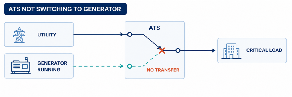
Automatic transfer switch not switching to the generator while the generator is runningIf an automatic transfer switch is not switching to generator power, find the first failed step in the transfer sequence. Confirm whether the ATS detected an unacceptable utility source, issued the engine-start command, received acceptable generator voltage and frequency, completed its programmed delay, operated the switching mechanism, and returned the correct position feedback. The first missing state normally identifies the fault area.
A running generator does not prove that the ATS is ready to transfer. The generator output breaker may be open, voltage or frequency may remain outside the controller acceptance window, a phase may be missing, a permissive input may be absent, or the mechanism may fail after the controller issues the command. Troubleshooting becomes faster when these conditions are checked in sequence instead of replacing the controller first.
Safety boundary: an ATS enclosure can contain live utility and generator conductors at the same time. Operators may record indicators, alarms and controller events without opening energized compartments. Voltage measurements, continuity tests, manual mechanism operation and internal inspection must follow the ordered equipment manual, site switching procedure and applicable electrical-safety rules, and should be performed only by qualified personnel.
Read the Failure as a Broken Transfer Sequence
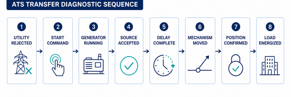
ATS diagnostic sequence from utility failure to generator load transferAn automatic transfer is a chain of decisions rather than one movement. A typical utility-to-generator sequence is:
- The controller monitors the normal source.
- The normal source becomes unacceptable for longer than the programmed detection delay.
- The ATS changes its engine-start contact to command the generator.
- The generator starts and develops voltage and frequency at the ATS alternate-source terminals.
- The controller accepts the alternate source after its stabilization delay.
- Interlocks and permissives allow a transfer command.
- The mechanism disconnects the normal source and connects the alternate source according to its transition design.
- Auxiliary contacts confirm the new position.
- Voltage appears at the load terminals and the generator carries the transferred load.
Start with the controller event log and front-panel source/position indicators. Write down the last confirmed step. If the generator never receives a start request, inspecting power contacts will not solve the problem. If the controller shows the generator as available but the mechanism never moves, changing generator settings will not solve it either.
Record These Parameters Before Changing a Setting
The useful parameters are the values that determine whether the controller accepts a source and permits movement. Record the current settings and observed values before making any change. Acceptance windows and delay ranges are controller- and project-specific; the table identifies what to capture, not universal setpoints.
| Parameter | What to record | Why it matters | Evidence source |
|---|---|---|---|
| Nominal source voltage | Configured nominal value and system phase arrangement | Wrong configuration can make a healthy source appear unacceptable | Approved settings file, nameplate and one-line diagram |
| Undervoltage and overvoltage limits | Pickup/dropout values or percentage settings for each source | The ATS transfers only after source voltage crosses the applicable limit and delay | Controller menu and sequence of operation |
| Frequency limits | Underfrequency/overfrequency acceptance values | A running generator may still be rejected while speed is unstable | Controller menu and generator data |
| Phase monitoring | Phase loss, phase sequence and phase-unbalance functions enabled | One incorrect phase condition can block source acceptance | Controller status and settings |
| Source-failure delay | Time from unacceptable utility to engine-start action | Prevents starting for a brief disturbance | Active-timer display and approved settings |
| Generator stabilization delay | Time after the alternate source becomes acceptable before transfer | Allows voltage and frequency to settle | Controller timer and event log |
| Transfer and mechanism timeout | Permitted time for open/close command and position confirmation | A timeout separates slow or failed motion from normal delay | Alarm code, event log and controller manual |
| Retransfer and cool-down delays | Utility-return verification time and unloaded generator run time | Explains why the ATS remains on generator or why the engine continues running | Controller and generator settings |
| Engine-start contact logic | Close-to-start or open-to-start; terminal numbers and observed state | Incompatible logic prevents the generator receiving the intended command | ATS schematic and generator remote-start diagram |
| Control supply | Rated AC/DC control voltage and value during the failed event | A control-voltage dip can reset the controller or drop the actuator | Ordered schematic and qualified measurement |
| Permissive and inhibit inputs | Normal state and state during the failed transfer | An external contact may intentionally block movement | I/O status screen, PLC/BMS log and wiring diagram |
| Position feedback | Normal-open, alternate-closed and intermediate-position contact states | The controller may command correctly but fail to confirm movement | Controller I/O screen and auxiliary-contact diagram |
| Observed state | Likely fault area | Best next evidence |
|---|---|---|
| Utility failed; generator does not start | ATS mode, sensing, start delay, start contact or control wiring | Normal-source status, active timer, start-output indication and generator remote-mode status |
| Generator runs; ATS says source unavailable | Generator output, breaker, voltage/frequency, phase or sensing circuit | Generator-available indicator, controller readings and qualified measurement at source terminals |
| Generator is available; no transfer command | Delay, inhibit, permissive, test mode or control logic | Active timer, inhibit input, alarm and event log |
| Transfer command appears; mechanism does not move | Control supply, actuator, coil, motor, interlock or mechanical obstruction | Command output, actuator supply and position feedback |
| Mechanism moves; load remains dead | Open generator breaker, damaged contact path, output connection or downstream protection | ATS position, source and load voltage, breaker states |
| Transfer occurs; generator trips or voltage collapses | Load step, generator capacity, inrush, protection setting or phase problem | Generator event log, current, frequency and voltage during the transfer |
Confirm Source Recognition from Utility Failure to Generator Availability
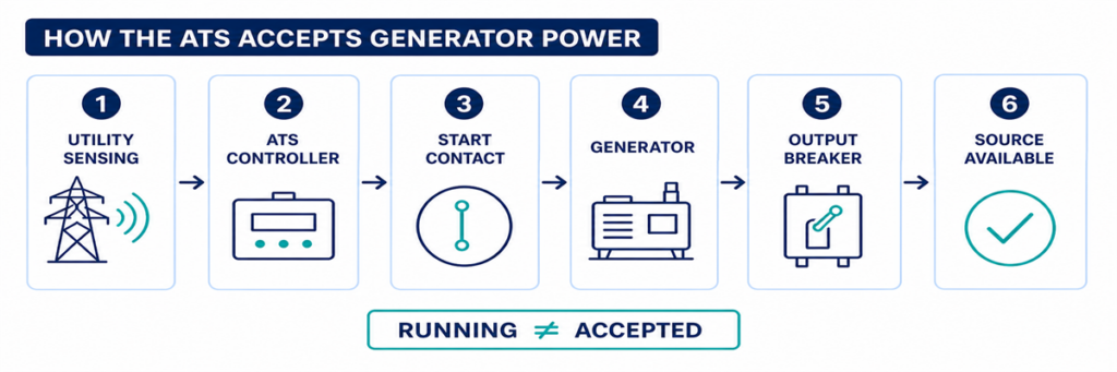
How an ATS detects and accepts generator power before transferringCheckpoint 1: Did the ATS Actually Reject the Utility Source?
The ATS normally remains on utility while the controller considers that source acceptable. A facility operator may see dim lights, a partial outage or a downstream panel failure while the voltage-sensing points at the ATS remain within their programmed limits. In that case, refusing to transfer may be correct behaviour rather than an ATS fault.
Check the normal-source indicator and the controller values for each monitored phase. Compare them with the configured undervoltage, overvoltage, frequency, phase-loss and phase-sequence functions for the ordered controller. Also check the time delay on normal-source failure. A short disturbance may disappear before that timer expires, deliberately preventing an unnecessary generator start.
Common reasons the controller still accepts utility
- The outage is downstream of the ATS sensing point.
- Only a circuit or load feeder has failed.
- The undervoltage pickup/dropout setting does not match the intended operating window.
- A sensing fuse or wiring fault gives the controller an incorrect state.
- The controller is reading the wrong nominal-voltage or source configuration.
- The source-failure delay has not expired.
Do not lower a voltage threshold simply to force transfer. First establish the intended source-quality limits and verify that the sensing configuration matches the system. A loose neutral or missing phase can create hazardous voltages that require investigation, not a wider acceptance window.
Checkpoint 2: Was the Generator Start Command Issued?
When the normal source is rejected, many utility-to-generator ATS controllers operate a dry contact connected to the generator remote-start circuit. The contact may close to start or open to start, depending on the generator and ATS design. The two devices must use compatible logic.
First confirm that the ATS is in AUTO or its normal operating mode. Maintenance, monitor, manual, inhibit, fire-control and exercise modes can intentionally block automatic transfer or change the start sequence. Record active alarms and input states before resetting anything; a reset can erase the most useful evidence.
If the controller shows that the start output has operated but the generator remains stopped, inspect the interface between the ATS and generator. Typical causes include an open control conductor, incorrect use of normally open or normally closed terminals, a loose terminal, a blown control fuse, a disabled generator remote mode, low starting-battery voltage or a generator shutdown alarm.
A jumper should not be improvised across start terminals unless the manufacturer’s procedure explicitly requires it and the test is controlled by qualified personnel. Unexpected generator starting can expose people working on the engine, alternator or downstream circuit.
Checkpoint 3: Is Generator Power Reaching the ATS?
A generator can be running while delivering no usable power to the transfer switch. The engine state and alternate-source electrical state are separate checkpoints.
Look for the controller’s generator-available indication. Check whether the generator output breaker is closed and whether any external isolator, feeder breaker or fuse between the generator and ATS is open. Inspect the generator controller for overvoltage, undervoltage, overspeed, underspeed, excitation, phase or breaker-trip alarms.
Where live testing is authorized, qualified personnel should measure the source at the ATS terminals—not only at the generator display. Confirm the correct phase-to-phase and, where applicable, phase-to-neutral voltages, frequency and phase rotation. A good reading at the alternator but no reading at the ATS points to the intervening breaker, cable, termination or protective device.
Why the ATS may reject a running generator
- Voltage remains outside the programmed acceptance band.
- Frequency has not stabilized.
- One phase is absent or the phase sequence is incorrect.
- The controller nominal voltage or sensing ratio is configured incorrectly.
- The generator breaker is open or has tripped.
- A sensing fuse, transformer or harness is open.
- The generator reaches acceptable conditions only briefly and drops out again.
Do not treat the generator’s unloaded panel voltage as final proof. The relevant value is the source condition recognized by the ATS, and later the voltage and frequency retained when the load is applied.
Trace the Transfer Command, Mechanism and Position Feedback
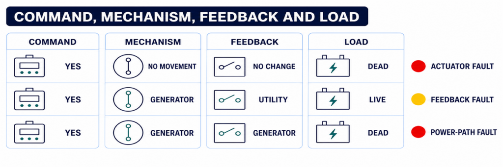
ATS command, switching mechanism, position feedback and load voltage diagnostic comparisonCheckpoint 4: Is a Timer or Permissive Holding the Transfer?
Once the alternate source is acceptable, transfer may still be delayed intentionally. A generator-warm-up timer allows voltage and frequency to stabilize. Other applications require a load-shed confirmation, elevator or motor sequence, UPS status, fire-system input, process permissive, or remote authorization before the switch moves.
Use the controller display to identify which timer is active and whether it is counting. Compare the setting with the approved sequence of operation rather than assuming a delay is excessive. On some controllers a test button or delay-bypass function can shorten a test sequence; this must be used only under the model-specific procedure and when the load is ready to transfer.
If the timer finishes but no command follows, inspect logic inputs for transfer inhibit, emergency inhibit, external trip, source preference, manual retransfer or load-shed confirmation. A permanently energized field contact can make the ATS appear defective while it is obeying the programmed interlock.
Checkpoint 5: Did the Controller Command the Mechanism?
This checkpoint separates a logic problem from an actuator or power-switching problem. Review the event log for commands such as open normal, close alternate, transfer initiated or failure to close. Compare the displayed command with the actual position indicators.
If no command was produced even though source and permissive conditions appear correct, possible causes include an active inhibit, configuration error, failed output, controller power problem or internal controller fault. Verify the controller supply and connectors using the manufacturer’s service instructions before condemning the controller.
If a command was produced, determine whether control voltage reached the relevant motor, solenoid, shunt trip, closing coil or breaker accessory. The exact circuit depends on whether the ATS uses a dedicated switching mechanism, contactors or motorized circuit breakers. Do not apply a generic terminal diagram to a different mechanism.
Checkpoint 6: Can the Switching Mechanism Complete Its Motion?
A controller can issue the correct command while the power mechanism remains in its previous position or stops between positions. Possible causes include:
- missing or low actuator control voltage;
- a blown control fuse or open control transformer secondary;
- a failed motor, solenoid, closing coil or shunt-trip circuit;
- a charged-spring or stored-energy mechanism that is not ready;
- an electrical or mechanical interlock that has not released;
- a breaker that has tripped and requires reset before closing;
- binding, contamination, corrosion or a shipping/maintenance obstruction;
- misaligned or failed limit switches and auxiliary contacts.
Listen for a command and observe the approved external position indication, but do not repeatedly cycle a mechanism that stalls or chatters. Repeated commands can overheat a coil or motor and damage contacts or linkages.
Manual operation is not an ordinary live troubleshooting shortcut. Manufacturer instructions commonly require both utility and generator sources to be isolated before using a manual handle. Follow the exact procedure for the model, verify absence of voltage, and preserve any stored-energy precautions.
Checkpoint 7: Does Position Feedback Agree with the Power Path?
The controller may use auxiliary contacts to prove that one source opened and the other closed. If the mechanism moves but the feedback contact does not change, the controller can report a failed transfer or block the next command. A loose plug, incorrect auxiliary-contact wiring, failed microswitch or mechanical misalignment can create this mismatch.
Compare three independent pieces of evidence:
- the controller’s commanded state;
- the approved mechanical position indicator;
- the electrical state at the load terminals.
These states should agree. If the controller says “load on generator” but the load terminals remain dead, investigate the generator breaker, power contacts, bus connections and downstream protective devices. If load voltage is present but the controller does not confirm position, the feedback circuit is the stronger suspect.
When the ATS Transfers but the Generator Cannot Hold the Load
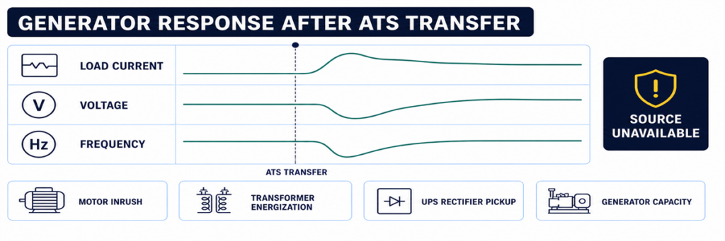
Generator voltage and frequency drop after an automatic transfer switch transfers the loadSome systems complete the movement and then immediately return, trip or lose voltage. That is not the same symptom as “no transfer.” It indicates that the alternate source became unacceptable during or after the load step, or that protection operated.
Review generator voltage, frequency and current trends at the transfer instant. Large motors, transformers, UPS rectifiers and simultaneous load pickup can cause voltage dip or frequency decay. A generator breaker may trip because of overload, short circuit, earth fault or an incorrect protection setting. Phase imbalance or a loose neutral can create a source-quality failure even when total kW appears reasonable.
If the transferred load or generator capacity is uncertain, rebuild the current and load assumptions from the approved load schedule and generator data. The JUTRION generator sizing calculator for ATS backup provides a first-pass check of running load and starting demand. It does not diagnose a control failure, and its result must be verified against the generator manufacturer’s transient-performance data.
Use a Controlled Functional Test to Reproduce the Sequence
A controlled test is more useful than waiting for the next outage. Prepare the load, generator and responsible personnel, then use the test method specified for the ordered ATS. The procedure should verify:
- normal source is initially acceptable and carrying the load;
- the test command initiates the intended engine-start sequence;
- the generator reaches acceptable voltage and frequency;
- the programmed transfer delay operates;
- the mechanism reaches the alternate position;
- the generator carries the intended load without unacceptable voltage or frequency deviation;
- normal-source return and retransfer delay operate;
- the generator completes its cool-down period and stops;
- alarms, event logs, remote indications and position feedback agree throughout.
Do not simulate a failure by disconnecting arbitrary sensing wires or opening energized compartments. Use the controller’s approved test function or the project test procedure. Life-safety, fire-pump, medical, data-centre and continuous-process systems require coordination before any transfer test.
Capture the Evidence Before Resetting or Replacing Parts
Intermittent transfer faults are difficult to diagnose after power has returned and alarms have been cleared. Capture evidence before resetting the system:
- ATS manufacturer, model, controller type and serial number;
- normal and alternate source voltage, frequency and phase configuration;
- controller mode and source-available indicators;
- event and alarm codes with timestamps;
- active delay and its remaining time;
- engine-start output state and generator remote-mode state;
- generator output-breaker position;
- commanded position, mechanical position and feedback state;
- whether the failure occurred unloaded, during transfer or after load pickup;
- recent maintenance, setting changes or wiring work.
This record prevents “controller fault” from becoming the default diagnosis. It also allows a manufacturer or service technician to distinguish an ATS problem from a generator, field-wiring, protection or load problem.
Use the Exact Symptom to Enter the Correct Checkpoint
“The ATS did not transfer” is not specific enough for diagnosis. Record the last state the system completed, then enter the corresponding checkpoint above. This prevents generator, controller and mechanism faults from being mixed together.
| Fault report | First checkpoint | Do not begin by replacing |
|---|---|---|
| Generator did not start | Utility sensing and engine-start output | Power-switching mechanism |
| Generator runs, source unavailable | Generator output at ATS and source settings | ATS main contacts |
| Both sources available, no command | Timers, mode, inhibits and permissives | Generator AVR |
| Command present, no motion | Control power, actuator and interlock | Complete controller without output checks |
| Motion present, wrong status | Auxiliary contacts and position feedback | Generator |
| Transfer followed by collapse | Loaded voltage, frequency, current and protection event | ATS sensing before reviewing the generator event |
| No retransfer to utility | Utility acceptance and return logic | Generator start circuit |
Interpret Controller Indicators Without Treating Them as Measurements
Front-panel indicators are the safest first evidence, but each answers a limited question. A “generator available” LED usually means the controller has accepted the values it senses; it does not prove every phase is present at the load terminals. A “load on generator” indication may be driven by an auxiliary contact; it does not independently measure current flowing to the load.
Use the indicators to form a test hypothesis:
- Normal available: the controller accepts the normal source at its sensing inputs.
- Generator available: alternate-source voltage and frequency have met the configured acceptance logic.
- Engine start active: the controller has commanded its start-output state; field wiring and generator response still require confirmation.
- Transfer timer active: the controller is intentionally waiting, not necessarily stalled.
- Load connected: a position input has changed; verify actual output voltage if the load remains dead.
- Transfer failed: the commanded position was not confirmed within the permitted time.
- Source unavailable: a sensed value is outside acceptance, but the display may not identify whether the cause is the source, sensing circuit or configuration.
If the display provides per-phase voltage and frequency, compare the values with a qualified independent measurement when safe and authorized. A large disagreement points toward sensing wiring, fuses, transformers, selector plugs or configuration. Agreement with an out-of-range value points toward the source itself.
Check Control Power Before Blaming the Controller
A blank screen, intermittent reset or missing output can result from a control-power problem outside the electronic controller. Depending on the ATS design, control power may come from one source, both sources through selection circuitry, a control transformer, a DC supply or an internal power module.
Review the correct schematic and identify which supply should energize the controller at each stage. During a utility failure, an arrangement that normally powers controls from utility must transition to an alternate control source or stored energy. A blown fuse, incorrect transformer tap, loose plug, low DC voltage or failed selector circuit can cause the controller to restart at exactly the time it should transfer.
Evidence of a control-power problem includes:
- display or LEDs resetting when a source fails;
- event-log timestamps restarting;
- relays chattering rather than holding;
- an actuator beginning motion and dropping out;
- normal operation in manual test but failure during a real source interruption;
- different behaviour when the panel door or wiring harness is moved.
Measure control voltage at the condition that produces the fault, not only during stable normal operation. Any live measurement requires appropriate equipment, access boundaries and qualified personnel.
Use Event Timing to Find Intermittent Transfer Failures
An ATS that works during inspection but failed during an outage needs a timeline. Align records from the utility monitor, ATS controller, generator controller, protective devices, BMS or SCADA and critical-load equipment. Even controllers without detailed waveform capture usually preserve enough event order to identify the missing link.
A useful event timeline records:
- the first normal-source abnormality;
- the moment the ATS declared normal unavailable;
- engine-start output operation;
- estado de arranque y funcionamiento del generador;
- tensión/frecuencia de la fuente alternativa disponible;
- orden de transferencia;
- confirmación de apertura de la fuente normal;
- confirmación de cierre de la fuente alternativa;
- restablecimiento de la tensión de carga;
- cualquier evento posterior de disparo, retransferencia o fuente no disponible.
La temporización expone fallas que una inspección estática no detecta. Por ejemplo, si el generador está disponible durante dos segundos y luego desaparece, investigue su estabilización y salida. Si la orden de transferencia y la alarma de fallo al cerrar están separadas por el tiempo de espera del mecanismo, investigue la alimentación del actuador y la realimentación. Si el controlador se reinicia entre la pérdida de la fuente normal y el arranque del motor, investigue la continuidad de la alimentación de control.
Las pistas ambientales importan
Registre si las fallas coinciden con baja temperatura, alta humedad, condensación, polvo, vibración, carga pesada, antigüedad de la batería o largos períodos de inactividad. Conectores intermitentes, mecanismos pegajosos, baterías de arranque débiles y calentadores de gabinete pueden pasar una prueba diurna cálida y fallar durante un corte nocturno. La pista es la correlación, no la suposición; reproduzca la condición de manera segura antes de reemplazar piezas.
Distinga una falla del ATS de una falla del generador o aguas abajo
El ATS se encuentra entre dos fuentes y una carga, por lo que los síntomas a menudo se atribuyen al equipo equivocado. Use límites en los terminales de la fuente normal, los terminales de la fuente alternativa y los terminales de carga.
| Evidencia | Área más probable | Razón |
|---|---|---|
| Sin salida de arranque del ATS después de una falla confirmada de la fuente | Detección del ATS, modo, temporizador o lógica de arranque | Todavía no se ha solicitado al generador que actúe |
| La salida de arranque cambia; el generador no gira | Cableado de campo, entrada remota del generador, batería o alarma del generador | La orden salió del ATS |
| La pantalla del generador muestra tensión; los terminales alternativos del ATS no | Interruptor del generador, alimentador o terminación | La energía se pierde entre el generador y el ATS |
| La tensión alternativa llega al ATS; el controlador la lee como no disponible | Circuito de detección, ajustes o entrada del controlador | La energía existe pero no es aceptada |
| Fuente alternativa aceptada; orden de cierre ausente | Lógica del ATS, retardo, inhibición o permiso | No se ha solicitado al mecanismo que se mueva |
| Orden de cierre y alimentación del actuador presentes; sin movimiento | Actuador, enclavamiento o mecanismo | La lógica y la entrega de control están comprobadas |
| Terminales de carga del ATS energizados; panel aguas abajo sin energía | Interruptor aguas abajo, cable o sistema de carga | El interruptor de transferencia ha entregado energía |
Este método de límites también mejora la comunicación con los proveedores. Un informe que indique “la tensión del generador estaba presente en los terminales alternativos del ATS, el controlador permaneció no disponible, ajustes y fusibles de detección verificados” es procesable. “El ATS no funciona” no lo es.
Verifique la retransferencia y el enfriamiento como parte del mismo sistema
Una secuencia automática completa no termina cuando la carga alcanza la energía del generador. Cuando la red regresa, el controlador normalmente verifica que permanezca aceptable durante un retardo de retorno, transfiere la carga de vuelta y mantiene el generador funcionando sin carga durante un período de enfriamiento antes de liberar la orden de arranque.
Si la red ha regresado pero el ATS permanece en el generador, verifique la aceptación de la fuente normal, el retardo de retorno, el modo de retransferencia manual, la preferencia de fuente y las entradas de inhibición externas. En aplicaciones donde el retorno se supervisa intencionalmente, el sistema puede requerir una orden del operador aunque se haya permitido la transferencia automática al generador.
Si la carga vuelve a la red pero el generador sigue en marcha, determine si el contacto de arranque del ATS permanece en estado de marcha, si el cableado de campo está en cortocircuito o si la lógica de enfriamiento o de ejercicio del propio generador está activa. Evite modificar los temporizadores del ATS y del generador a la vez; hacerlo dificulta demostrar la causa final.
Ponga en servicio la secuencia completa y evite fallos repetidos
Muchos fallos de transferencia se originan en la interfaz entre equipos suministrados por distintas partes. La puesta en servicio debe verificar la cadena completa, no solo que cada componente se encienda.
Confirme las definiciones de las fuentes
Registre la tensión nominal, la frecuencia, la secuencia de fases, la disposición del neutro y la preferencia de fuente. Confirme las selecciones de detección del controlador o las tomas del transformador con respecto al sistema real. Verifique que ambas fuentes y el ATS sean compatibles antes de intentar la transferencia.
Pruebe la interfaz de arranque del motor
Documente si el generador espera lógica de cierre para arrancar o de apertura para arrancar y qué terminales se utilizan en ambos extremos. Confirme el modo remoto, la continuidad de los conductores y la respuesta a un comando de prueba aprobado del ATS.
Pruebe cada temporizador e inhibición
Registre los ajustes de retardo por fallo de fuente, retardo de arranque del motor, estabilización del generador, transferencia, retorno y enfriamiento. Opere los contactos de inhibición externa, deslastre de carga y permisivos uno a la vez y verifique que la indicación del controlador coincida con la secuencia prevista.
Pruebe la posición y el estado remoto
Verifique las salidas de conectado a red, conectado a fuente alternativa, fuente disponible, alarma común y fallo de transferencia en la pantalla local y en el sistema de supervisión remoto. Una realimentación mal asignada puede hacer que un ATS en buen estado parezca fallado ante el BMS, o bien ocultar un fallo real.
Prueba bajo una carga representativa
Una prueba de movimiento sin carga demuestra la mecánica y parte de la cadena de control, pero no demuestra la respuesta del generador a la toma de carga ni el rendimiento de la ruta de contactos. Cuando el procedimiento del proyecto lo permita, realice una transferencia con carga representativa y registre tensión, frecuencia y corriente. Escalone las cargas cuando la secuencia operativa aprobada lo requiera.
Deje un registro de referencia
Guarde los ajustes, valores de temporizadores, registros de eventos, lecturas de fuente, tiempos de transferencia y estados de retroalimentación de posición de una prueba exitosa. Los técnicos futuros podrán comparar un evento fallido con esta secuencia conocida como buena en lugar de depender de la memoria.
Evite que la misma falla de no transferencia regrese
Ejercite el sistema completo a un intervalo apropiado para la aplicación y los requisitos locales, no solo el motor del generador. Un funcionamiento del motor sin carga no demuestra que el ATS detecte, transfiera, soporte carga, retransfiera y se detenga correctamente.
El mantenimiento debe incluir la inspección del cableado de control, terminales, fusibles, conectores, condición del gabinete, calentadores donde estén instalados, indicación de posición, operación mecánica bajo un procedimiento aislado aprobado, registros de eventos y baterías del generador. Revise los ajustes del controlador después de cambios de firmware, generador, transformador, protección o carga.
Para proyectos que seleccionen equipos de reemplazo, confirme la disposición de fuentes, tensión, frecuencia, corriente, polos y tratamiento del neutro, clase de transferencia, coordinación de cortocircuito, E/S del controlador y condiciones del gabinete. Utilice la calculadora de dimensionamiento de interruptores de transferencia automática JUTRION para filtrar la corriente de carga, un paso de clasificación adecuado y las preguntas iniciales de polos/configuración. No puede seleccionar el ATS final sin las verificaciones de corriente de falla, neutro, transición y controlador.
Después de confirmar esas entradas del proyecto, compare el resultado con la gama de interruptores de transferencia automática JUTRION. Las configuraciones disponibles de clase PC, clase CB y controlador aún deben coincidir con la fuente real, la protección y la secuencia operativa.
Preguntas Frecuentes
¿Por qué arranca el generador pero el ATS no transfiere?
Es posible que el ATS no detecte tensión o frecuencia aceptables del generador, que el interruptor del generador esté abierto, que haya un retardo de estabilización o una inhibición activa, o que el controlador ordene la transferencia mientras el mecanismo o el circuito de realimentación fallan. Identifique el primer estado faltante en la secuencia de transferencia.
¿Puedo mover manualmente un ATS a la energía del generador?
Solo bajo el procedimiento específico del modelo del fabricante. Muchos conmutadores de transferencia requieren que ambas fuentes estén desconectadas antes de la operación manual. Nunca use la manija manual como un atajo para solucionar problemas en vivo.
¿Por qué el ATS transfiere y luego regresa inmediatamente?
La fuente del generador puede quedar fuera de su ventana de aceptación de tensión o frecuencia cuando se aplica carga, o puede actuar el interruptor/protección del generador. Compruebe el registro de eventos y el comportamiento del generador durante el escalón de carga.
¿Puede un ajuste incorrecto del tiempo de retardo impedir que un ATS realice la transferencia?
Sí. Los retrasos por fallo de la fuente, arranque del motor, estabilización del generador y transferencia pueden hacer que una secuencia correcta parezca detenida. Una inhibición activa o un permiso también pueden bloquear la transferencia después de que finalice el temporizador.
¿Un controlador ATS en blanco significa que el interruptor completo ha fallado?
No necesariamente. La falta de alimentación del controlador, un fusible de control abierto, un problema en el transformador o en el arnés pueden dejar la pantalla en blanco. Verifique la ruta de alimentación del control según el procedimiento de servicio del fabricante antes de reemplazar el controlador.
Termine el diagnóstico en el primer estado faltante
No comience con el componente más costoso. Comience con la secuencia. Si el ATS nunca rechaza la red pública, investigue la detección y los ajustes. Si rechaza la red pública pero nunca solicita un arranque, investigue el modo, los temporizadores y el circuito de arranque. Si el generador funciona pero permanece no disponible, investigue su salida eléctrica y la ruta de detección del ATS. Si la fuente es aceptada pero el interruptor no se mueve, investigue los permisivos, la alimentación de control, el actuador y los enclavamientos. Si el mecanismo se mueve pero la carga permanece sin energía, verifique la ruta de potencia y la retroalimentación.
Ese orden basado en evidencia acorta el tiempo de inactividad y evita reemplazar un controlador por un interruptor del generador, un mecanismo por una inhibición activa, o un ATS completo por un conductor de control abierto.
