

Guía de Selección de RCBO para Circuitos Reales: Tipo A/AC, 30mA, Curvas B/C y Polos
Una solicitud de “32 A, 30 mA RCBO” no está lista para pedido. Identifica una clase de corriente de carga y un umbral de corriente residual, pero no identifica la forma de onda de falla, la corriente de arranque, el límite del cable, los conductores de suministro ni la corriente de cortocircuito disponible. Los mismos dos números podrían describir un circuito de tomacorrientes general, un banco de controladores LED o un alimentador de inversor—y esos circuitos pueden necesitar diferentes RCBO.
La respuesta práctica es elegir el RCBO en torno a la tarea de protección. Para un circuito final moderno típico, Tipo A y 30 mA suelen ser el punto de partida. La elección final aún depende de si la carga produce fuga electrónica, si la curva B puede tolerar el arranque, qué conductores deben desconectarse y si 6 kA es suficiente en el tablero.
Esta guía sigue tres archivos de proyecto en lugar de una secuencia de catálogo. Cada proyecto comienza con un riesgo diferente, luego termina con una descripción completa del RCBO que un contratista, fabricante de tableros o distribuidor puede realmente usar.
Tres circuitos que no deberían recibir el mismo RCBO
| Archivo de proyecto | Incertidumbre principal | Punto de partida probable | Decisión que controla el resultado |
|---|---|---|---|
| Circuito de tomacorrientes de oficina | Cargas electrónicas futuras y continuidad | Tipo A, 30 mA, RCBO individual | Capacidad del cable, nivel de falla e interfaz del tablero |
| Iluminación LED y panel de bomba pequeña | Corriente de arranque breve | Tipo A, 30 mA, curva B o C | Corriente de irrupción medida/declarada versus condiciones de desconexión por falla |
| Circuito trifásico respaldado por inversor | Forma de onda de corriente residual, potencia inversa y neutro | Tipo A/F/B definido por el equipo y 3P/3P+N/4P | Instrucciones del convertidor, topología de suministro y aprobación bidireccional |
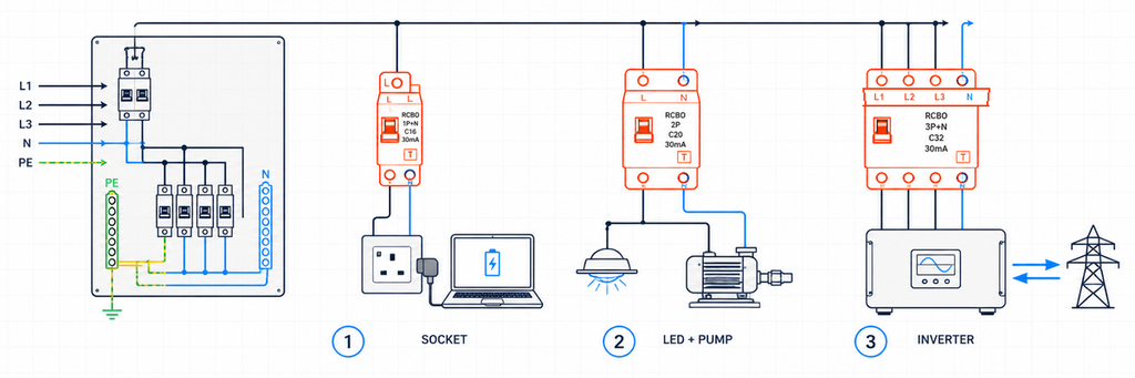
Tres circuitos finales diferentes que requieren selección de RCBO según su carga real y disposición de conductoresEstos ejemplos son ilustrativos, no registros de proyectos JUTRION completados. Su propósito es mostrar cómo un parámetro cambia porque el circuito cambia.
Archivo de proyecto 1: Un circuito de tomacorrientes de oficina
El primer circuito alimenta tomas de corriente generales en una oficina de 230 V. Actualmente, el equipo conectado incluye portátiles, monitores, cargadores y una impresora. Mañana los ocupantes pueden conectar diferentes aparatos electrónicos. Por lo tanto, el diseñador no puede garantizar que el circuito seguirá siendo una carga CA sinusoidal simple.
El Tipo A es el punto de partida defendible
El tipo AC responde a corriente residual alterna sinusoidal. El tipo A también responde a corriente residual pulsante de CC. La electrónica monofásica moderna suele contener rectificadores y fuentes de alimentación conmutadas, por lo que el tipo A es normalmente el punto de partida más práctico para un circuito de tomas no especificado.
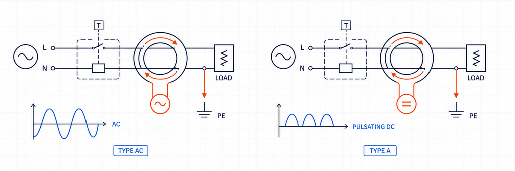
Comparación de forma de onda de corriente residual entre RCBO Tipo AC y Tipo AEl tipo A no es un sustituto universal para todos los tipos de RCD. Equipos capaces de producir corrientes residuales de CC suaves o de frecuencias mixtas particulares pueden requerir tipo F, tipo B u otra configuración declarada. Sin embargo, para un circuito general de tomas en oficina, el tipo A cubre una población de carga más realista que el tipo AC.
Por qué 30 mA y 20 A responden a preguntas diferentes
La especificación de oficina propone una clasificación de corriente residual de 30 mA para protección adicional bajo las reglas de instalación aplicables. Ese valor de 30 mA es IΔn; describe la función de corriente residual. No describe la corriente de carga que el circuito puede transportar.
Suponga que la corriente de diseño calculada es 17,2 A y el cable instalado tiene una capacidad de corriente corregida de 24 A. Un dispositivo de 20 A cumple la relación inicial de protección del conductor:
Ib ≤ In ≤ Iz
17,2 A ≤ 20 A ≤ 24 A
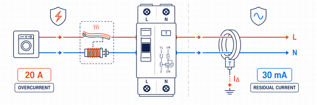
Protección contra sobrecorriente de RCBO de 20 amperios comparada con protección de corriente residual de 30 miliamperiosAquí, Ib es la corriente de diseño, In es la corriente nominal del RCBO e Iz es la capacidad corregida del cable. La temperatura ambiente, agrupamiento, aislamiento, método de instalación, armónicos y reglas nacionales ya deben estar reflejados en Iz. Elegir 25 A porque es el siguiente tamaño de catálogo excedería la capacidad declarada del cable.
Los RCBO individuales protegen la continuidad así como a las personas
Si varios circuitos de oficina comparten un RCCB, las fugas de sus filtros electrónicos se acumulan en el dispositivo compartido. Un evento de fallo a tierra también puede desconectar todos los MCB aguas abajo. Los RCBO individuales dividen la fuga por circuito y normalmente contienen un disparo por corriente residual en la rama afectada. Esto facilita la localización de fallos y reduce pérdidas innecesarias de servicio.
La arquitectura no elimina la planificación de fugas. La corriente normal del conductor de protección aún necesita margen por debajo del umbral del dispositivo, particularmente donde se conectan muchas fuentes de alimentación de TI o cables largos.
El resultado de oficina
230 V CA, RCBO 1P+N, 20 A, tipo A, 30 mA, curva B o C según verificación de irrupción y fallo, capacidad de corte superior al nivel de fallo medido/calculado del cuadro, compatible con el carril de la unidad de consumo declarada.
La curva y la capacidad de corte permanecen abiertas porque ninguna puede elegirse solo por “tomacorrientes de oficina”.
Archivo de proyecto 2: Iluminación LED junto a una bomba pequeña
El segundo panel contiene dos circuitos de salida con corriente normal similar. Uno alimenta un grupo de controladores LED; el otro alimenta una bomba pequeña de conexión directa a la línea. Ambos pueden producir un breve pico de corriente durante la energización, pero la fuente y la duración de ese pico difieren.
Curva B versus curva C es una decisión de irrupción y trayectoria de falla
Para las características comunes de minidisyuntores IEC, la curva B típicamente tiene un rango de operación instantánea alrededor de 3–5 veces In, mientras que la curva C está alrededor de 5–10 veces In. La curva D, a menudo alrededor de 10–20 veces In, se reserva para servicios de mayor irrupción que han sido específicamente diseñados. La operación exacta debe verificarse contra los datos aplicables del producto.
Un RCBO de curva C puede tolerar una corriente de arranque de corta duración mayor antes de que opere su elemento magnético. Eso no lo convierte en una mejor elección de propósito general. El umbral más alto también significa que el circuito debe entregar más corriente de falla para asegurar la desconexión instantánea.
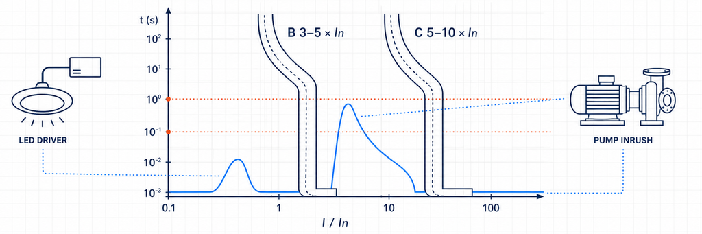
Rangos de disparo instantáneo de RCBO de curva B y curva C comparados con la corriente de irrupción de controladores LED y bomba| Evidencia del circuito | Lo que sugiere | Lo que debe verificarse a continuación |
|---|---|---|
| Pico de arranque bajo o controlado | La curva B puede seguir siendo adecuada | Curva del fabricante y eventos de conmutación normales |
| Pico corto y repetible por encima de la región magnética B | Considerar la curva C | Condiciones de bucle de falla/desconexión y protección del cable |
| Corriente de irrupción muy alta de transformador o motor | Solución C/D diseñada o método de arranque diferente | Corriente de falla disponible, coordinación y protección de equipos |
| El disparo ocurre después de funcionar durante minutos | Probablemente sobrecarga térmica en lugar de irrupción | Corriente de carga, temperatura del gabinete, terminales y cable |
| La indicación de disparo muestra operación por corriente residual | Cambiar B a C no lo resolverá | Fuga, aislamiento, humedad, enrutamiento del neutro y tipo de RCD |
Esta distinción evita un error de diagnóstico común. Un RCBO de curva B y uno de curva C con la misma marca de 30 mA tienen la misma sensibilidad nominal a la corriente residual. La letra de la curva pertenece a la sección de sobrecorriente; no hace que el RCBO sea más tolerante a las fugas a tierra.
Los controladores LED y los motores de bomba también cambian la cuestión del tipo de RCD
Los controladores LED contienen electrónica, por lo que el Tipo A es una base sensata. Un circuito de motor monofásico convencional también puede incluir un controlador electrónico, un arrancador suave o un variador de velocidad. Una vez que se introduce la electrónica de potencia, las instrucciones del equipo —no la palabra “motor”— determinan si el Tipo A sigue siendo adecuado o si se necesita el comportamiento Tipo F/B.
Los dos resultados del circuito
Después de verificar una irrupción modesta del controlador LED y una corriente de falla adecuada, el circuito de iluminación puede quedar como:
230 V AC, 1P+N, 16 A, Tipo A, 30 mA, curva B, 6 kA cuando la corriente de cortocircuito prospectiva verificada está por debajo de esa capacidad.
Si el registro de arranque de la bomba excede la región de la curva B pero el circuito cumple con los requisitos de desconexión de la curva C, el circuito de la bomba puede quedar como:
230 V AC, 1P+N o 2P según se requiera, 16 A, Tipo A (o tipo especificado por el equipo), 30 mA donde sea necesario, curva C, capacidad de corte adaptada al nivel de fallo del cuadro.
La diferencia no fue “iluminación versus motor” por la etiqueta. Fue el comportamiento de arranque medido o declarado, la forma de onda de corriente residual y la trayectoria de falla.
Archivo de proyecto 3: Un circuito trifásico respaldado por inversor
El tercer proyecto conecta un sistema trifásico de electrónica de potencia. Puede importar energía, exportar energía u operar de manera diferente cuando una fuente de respaldo está activa. Un atajo de catálogo como “tetrapolar, Tipo B” es inseguro porque el diseño del convertidor y la topología de suministro aún no se han establecido.
Deje que la documentación del convertidor defina el tipo de corriente residual
El Tipo F amplía el comportamiento del Tipo A para condiciones definidas de frecuencia mixta asociadas a cargas seleccionadas de inversores monofásicos. El Tipo B cubre un rango más amplio de corriente residual, incluyendo corriente continua suave bajo sus características aplicables. Algunos cargadores de vehículos eléctricos e inversores incorporan monitorización de corriente continua residual; otros requieren un dispositivo específico aguas arriba.
La elección no puede hacerse solo por la categoría del producto. Confirme:
- la forma de onda de corriente residual que el equipo puede producir;
- si la detección de corriente residual continua es interna;
- el requisito exacto de RCD/RCBO aguas arriba en las instrucciones del equipo;
- la coordinación con cualquier dispositivo de corriente residual aguas arriba;
- las reglas nacionales para la aplicación.
No confunda un RCBO Tipo B con un RCBO de curva B. El Tipo B describe la capacidad de detección de corriente residual. La curva B describe la respuesta instantánea de sobrecorriente. Un producto puede ser Tipo B con curva C.
Los polos siguen a los conductores, no al nombre de la carga
Una carga trifásica de tres hilos sin neutro puede usar una disposición 3P. Un sistema trifásico de cuatro hilos con neutro requiere 3P+N o 4P según lo definido por el producto, el sistema y las reglas de instalación. La hoja de datos debe mostrar si el neutro es conmutado, sólido o protegido contra sobrecorriente.
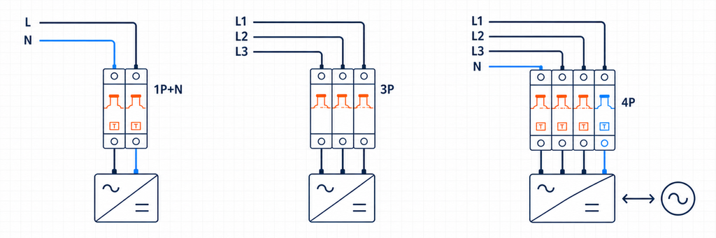
RCBO 1P más N, disposiciones de polos 3P y 4P para circuitos respaldados por inversor| Disposición | Sistema probable | Confirmación requerida |
|---|---|---|
| 1P+N | Línea y neutro monofásicos | Conmutación del neutro, dirección línea/carga y posición de la barra colectora |
| 2P | Monofásico con desconexión de dos polos | Qué polos están conmutados y protegidos contra sobrecorriente |
| 3P | Trifásico sin neutro | Sin necesidad de operación o detección de neutro |
| 3P+N | Trifásico con neutro | Comportamiento de conmutación/protección del neutro |
| 4P | Trifásico, cuatro hilos con operación de cuatro polos declarada | Operación simultánea y compatibilidad del sistema |
Cada conductor requerido por el arreglo de detección de corriente residual debe seguir el diagrama del fabricante. Un neutro prestado o derivado crea un desequilibrio y puede hacer que el dispositivo se dispare incluso cuando las cargas en sí están sanas.
La potencia inversa requiere un dispositivo bidireccional declarado
Equipos solares, baterías y de vehículo a red pueden alimentar el circuito en la dirección opuesta a una carga convencional. Un interruptor manual no prueba la idoneidad bidireccional. Verifique la dirección de suministro permitida, la orientación de los terminales, el rendimiento en cortocircuito en cada dirección, el comportamiento del neutro y el sistema de placa aprobado.
El RCBO es solo una parte de esta cadena de protección. No reemplaza el aislamiento requerido, las funciones anti-isla, la protección contra sobretensiones o la identificación segura de la fuente.
El resultado del circuito del inversor
400 V AC, 3P/3P+N/4P según el sistema real de conductores, tipo de corriente residual requerido por el fabricante del convertidor, sensibilidad requerida por las normas de aplicación, curva C/D solo tras arranque y verificación de fallo, uso bidireccional declarado donde la potencia puede invertirse, y capacidad de corte superior al nivel de fallo del proyecto.
Esta especificación es más larga porque el sistema tiene más interfaces. Acortarla a “4P C32 30 mA” descartaría las decisiones más propensas a afectar la compatibilidad.
El Decodificador de Clasificaciones: Lo que Cada Marcado Prueba
Los tres archivos del proyecto ahora pueden reducirse a una tabla de decodificación. Cada clasificación cierra un riesgo diferente; ningún valor único puede sustituir a otro.
| Campo del RCBO | Significado de ingeniería | Evidencia del proyecto | Fallo si se ignora |
|---|---|---|---|
| Voltaje/frecuencia nominal | Condiciones de suministro para operación declarada | Dibujos del sistema y datos del equipo | Operación incorrecta o clasificación no válida |
| En (A) | Corriente nominal de la sección de sobrecorriente | Ib, Iz corregido y carga de trabajo | Disparos por sobrecarga o cable no protegido |
| Curva B/C/D | Respuesta magnética instantánea | Datos de corriente de arranque y de fallo | Disparos de arranque por molestias o eliminación de fallos inadecuada |
| Tipo AC/A/F/B | Capacidad de forma de onda de corriente residual | Topología de carga e instrucciones del fabricante | Falta de respuesta correcta a la posible forma de onda |
| IΔn (mA) | Sensibilidad a la corriente residual | Objetivo de protección y regla de instalación | Nivel de protección incorrecto o mala continuidad |
| Polos/neutro | Conductores detectados, conmutados y protegidos | Diagrama unifilar y sistema de puesta a tierra | Aislamiento, detección o operación del neutro incorrectos |
| Capacidad de ruptura (kA) | Máxima carga de interrupción de cortocircuito declarada | Corriente de cortocircuito prospectiva | Dispositivo utilizado más allá de su capacidad de interrupción probada |
| Interfaz de dirección/tablero | Orientación de suministro y compatibilidad física | Hoja de datos actual y declaración del tablero | Instalación no válida, desajuste de barra colectora o problema de inversión de potencia |
IEC 61009-1:2024 establece los requisitos del producto y las pruebas para los RCBO para usos domésticos y similares dentro de su alcance declarado. No reemplaza el código nacional de instalación. La conformidad del producto responde a si el RCBO cumple con sus requisitos de producto declarados; la conformidad de instalación responde a si ese dispositivo se aplica correctamente en el circuito.
Por qué 10, 30, 100 y 300 mA no son grados de calidad
Un IΔn más bajo es más sensible, pero “más sensible” no significa “mejor para cada posición”. Los dispositivos de diez miliamperios pueden seleccionarse para funciones locales particulares o de mayor sensibilidad. Treinta miliamperios se utiliza ampliamente para protección adicional en circuitos finales. Los valores de cien y 300 mA pueden servir para roles seleccionados de equipos o riesgo de incendio.
Un dispositivo de 100 o 300 mA en la parte superior no reemplaza la protección de 30 mA en la parte inferior donde se requiere 30 mA. Inversamente, instalar protección instantánea de 30 mA tanto en niveles superiores como inferiores puede socavar la selectividad porque ambos dispositivos ven el mismo desequilibrio de falla a tierra.
Donde se utiliza protección contra corriente residual en la parte superior, coordine tanto el umbral como el tiempo de operación. Una función selectiva/con retardo de tiempo pertenece al nivel permitido por el diseño de la instalación; no debe retrasar una función protectora de circuito final que se requiere que opere de inmediato.
6 kA o 10 kA es una decisión de ubicación
La capacidad de ruptura debe ser al menos la corriente de cortocircuito prospectiva en el punto de instalación del RCBO bajo sus condiciones declaradas. Un tablero cerca de un transformador puede tener un nivel de falla más alto que un circuito final distante, incluso cuando el edificio distante es físicamente más grande.
Utilice un cálculo, medición o registro de nivel de falla de proyecto confiable. Si se propone protección de respaldo en la parte superior, utilice una combinación de fabricante probada o declarada. Un interruptor en la parte superior con una gran capacidad de interrupción no transfiere automáticamente esa calificación a un RCBO en la parte inferior.
La protección de respaldo y la selectividad también son diferentes. Una combinación puede interrumpir una alta falla de manera segura mientras ambos dispositivos se abren. Si la continuidad requiere que solo el circuito en la parte inferior se desconecte, obtenga evidencia de selectividad para el rango de corriente relevante.
Convierta los datos del proyecto en una descripción ordenable
Antes de seleccionar un modelo, reúna un breve registro del proyecto:
- país/mercado y requisitos de instalación aplicables;
- voltaje del sistema, frecuencia y disposición de puesta a tierra;
- conductores monofásicos o trifásicos, incluyendo neutro;
- descripción de carga, topología del convertidor electrónico y corriente de arranque;
- corriente de diseño y capacidad de cable corregida;
- objetivo de protección contra corriente residual requerido;
- corriente de cortocircuito prospectiva en el tablero;
- dirección del flujo de potencia en cada modo de operación;
- modelo de unidad de consumo/tablero de distribución, barra colectora y ancho de módulo disponible;
- requisitos de terminal, ambientales, de indicación y accesorios.
Luego escriba la especificación en una línea:
[voltage/frequency], [poles and neutral arrangement], [In], [curve], [Type AC/A/F/B], [IΔn], [breaking capacity], [supply direction], [product standard/market approval], [board and busbar interface].
Esta línea es más útil que pedir a un proveedor “un buen RCBO.” Proporciona a los equipos de ingeniería y compras la misma referencia y expone la información faltante antes de que se comprometan muestras o producción.
Valide el RCBO Seleccionado en la Placa Actual
Un conjunto de calificación técnicamente correcto aún puede fallar en la interfaz de ensamblaje. Antes de que un distribuidor acepte una gama de reemplazo o un OEM libere una unidad de consumo, el RCBO seleccionado debe ser verificado en el recinto previsto con la barra colectora, conductores y accesorios previstos.
Ajuste mecánico y de cableado
Confirme el ancho del módulo, el compromiso del riel DIN, la posición del diente de la barra colectora, la ubicación del neutro y el acceso a los terminales. Un dispositivo descrito como 1P+N puede usar un conductor neutro volador, un terminal neutro en un lado particular o un paso de barra colectora diferente de otro dispositivo 1P+N. Dimensiones frontales similares no prueban la intercambiabilidad.
Verifique el material del conductor permitido, la sección transversal rígida/flexible y los requisitos de casquillo. Prepare los conductores según lo declarado y aplique el par de apriete especificado en los terminales. Una conexión suelta puede generar calor sin exceder la corriente de carga del circuito, mientras que un par de apriete excesivo puede dañar el terminal o el conductor.
Evidencia funcional
La puesta en marcha debe distinguir los dos sistemas de disparo. Donde el dispositivo proporciona indicación separada, registre si una operación de prueba se informa como corriente residual o sobrecorriente. Verifique la función del botón de prueba bajo las condiciones de suministro indicadas por el fabricante, luego complete las pruebas de instalación requeridas por las normas aplicables. El botón de prueba verifica un camino funcional interno; no mide el bucle completo de falla a tierra, la condición de aislamiento o cada requisito de tiempo de disparo.
Para circuitos con muchas cargas electrónicas, registre la corriente de carga normal, el pico de arranque y la fuga en reposo después de la puesta en marcha. Esos tres valores crean una línea base. Si aparecen disparos meses después, el mantenimiento puede comparar nuevas evidencias con la condición original en lugar de reemplazar dispositivos por prueba y error.
Temperatura y agrupamiento
Varios dispositivos modulares cargados montados uno al lado del otro pueden operar en un ambiente local más cálido de lo que sugiere la temperatura ambiente. La ventilación del recinto, los componentes adyacentes que producen calor, el tamaño del conductor y la carga sostenida afectan la temperatura. Aplique las instrucciones de desclasificación o separación del fabricante donde sea relevante; no responda a un disparo térmico aumentando la calificación en amperios sin volver a verificar la protección del cable.
Control de lote y documentación
Para un OEM o distribuidor, bloquea los atributos aprobados en la lista de materiales: modelo exacto, curva, tipo de corriente residual, IΔn, polos, capacidad de ruptura, disposición de terminales, aprobación y accesorios compatibles. Un sustituto que solo coincida en corriente y ancho puede cambiar silenciosamente el tipo de forma de onda o el comportamiento del neutro.
Retén la hoja de datos actual, los documentos de declaración/certificación requeridos por el mercado objetivo, el diagrama de cableado y la identificación del lote con el registro de muestra aprobado. Esto convierte la selección en un control de producción repetible en lugar de una conversación de ingeniería única.
Separar la Conformidad del Producto de la Conformidad de Instalación
Una marca IEC es importante, pero no decide dónde o cómo se puede instalar el RCBO. IEC 61009-1:2024 define requisitos generales y ensayos para RCBO destinados a usos domésticos y similares dentro de su ámbito declarado. Las normas nacionales de cableado, regulación local, especificaciones del proyecto y la autoridad competente determinan la aplicación de la instalación.
| Pregunta | De dónde proviene la respuesta | Ejemplo |
|---|---|---|
| ¿Se evaluó el RCBO como un producto? | Norma del producto, certificación y documentación del fabricante | Tensión declarada, corriente, IΔn, tipo y capacidad de cortocircuito |
| ¿Se requiere protección contra corriente residual aquí? | Normas nacionales de instalación y diseño de proyectos | Circuito de enchufe, exterior, ubicación húmeda o equipo especial |
| ¿Qué tipo de corriente residual está permitido? | Normas de instalación más instrucciones del equipo | Restricción en el Tipo AC o requisito creado por equipos convertidores |
| ¿Desconectará el circuito a tiempo? | Cálculo/prueba de instalación y característica del dispositivo | Condiciones del lazo de falla para una curva B/C/D elegida |
| ¿Puede el RCBO encajar en este tablero? | Declaraciones del sistema de tablero y del fabricante del dispositivo | Barra colectora, terminales, posición neutra y clasificación de la envolvente |
Esta distinción es importante en proyectos de exportación. Una configuración de producto aceptada en un mercado puede requerir un tipo de corriente residual diferente, disposición de polos, marca de aprobación o sistema de tablero de distribución en otro. No convierta una norma nacional en una afirmación universal de IEC, y no asuma que un certificado de componente aprueba el panel completo.
La Guía de selección de RCD de BEAMA es una fuente autorizada útil para el razonamiento sobre formas de onda y aplicaciones, particularmente en torno a cargas electrónicas modernas. Sus referencias de instalación regional aún deben aplicarse dentro de su propia jurisdicción. Para otro mercado, utilice las normas nacionales relevantes e instrucciones del equipo.
Dónde encaja un RCBO—y dónde no
Un RCBO combina protección contra corriente residual con protección contra sobrecarga y cortocircuito. Un Interruptor diferencial (RCCB) normalmente requiere protección contra sobrecorriente coordinada, mientras que un Interruptor magnetotérmico (MCB) no proporciona protección contra corriente residual. La arquitectura de RCBO por circuito a menudo mejora la continuidad y el aislamiento de fallas, pero aún debe coordinarse con la protección aguas arriba y el tablero de distribución.
Un RCBO normalmente no reconoce firmas de arco peligrosas. Si la mitigación de arco es parte del proyecto, utilice el guía AFDD de JUTRION para mapear las funciones de protección requeridas. Los RCBOs tampoco reemplazan a los SPDs, aisladores o protección específica del equipo simplemente porque varias funciones comparten una envolvente.
Elija la función de protección antes del número de catálogo
El circuito de oficina comenzó con cargas electrónicas impredecibles, por lo que la protección Tipo A y de 30 mA individual controló la decisión. Los circuitos de iluminación y bomba comenzaron con el comportamiento de arranque, por lo que la elección de la curva B/C dependió tanto de la corriente de arranque como de la de falla. El circuito del inversor comenzó con la forma de onda, topología del conductor y potencia inversa, por lo que las instrucciones del equipo y la aprobación bidireccional importaron antes de la amperaje.
Esa es la regla de selección transferible: identificar la falla que el RCBO debe detectar, probar el cable y el camino de falla, luego completar la interfaz física. Un número de catálogo correcto es el resultado de ese proceso, no el punto de partida.
JUTRION ofrece RCBOs para distribución monofásica y trifásica con múltiples combinaciones de polos, corriente, sensibilidad, tipo de forma de onda, curva y capacidad de ruptura. Comparta el registro del proyecto anterior al solicitar soporte de selección para que el modelo propuesto pueda ser verificado contra el circuito real.
Preguntas Frecuentes
¿Debería elegir un RCBO Tipo A o Tipo AC?
El Tipo AC detecta corriente residual alterna sinusoidal, mientras que el Tipo A también detecta corriente residual continua pulsante. Debido a que muchos aparatos modernos contienen rectificadores y fuentes de alimentación conmutadas, el Tipo A suele ser el punto de partida más práctico para circuitos generales de enchufes, iluminación y aparatos. La elección final debe seguir las instrucciones del equipo conectado y las normas de instalación aplicables.
¿Es siempre la elección correcta un RCBO de 30 mA?
No. Un valor de corriente residual de 30 mA se utiliza comúnmente donde se requiere protección adicional, pero no es un valor universal para cada circuito. Se deben verificar las normas de aplicación, la fuga esperada, la selectividad aguas arriba y los requisitos del equipo. El valor de 30 mA tampoco determina la clasificación de corriente de carga del RCBO.
¿Cuál es la diferencia entre un RCBO Tipo B y un RCBO de curva B?
Describen funciones diferentes. El Tipo B identifica la capacidad de detección de corriente residual, incluyendo corriente continua suave dentro de las características declaradas del dispositivo. La curva B identifica el rango de operación instantánea de la sección de sobrecorriente. Por tanto, un RCBO puede tener comportamiento de corriente residual Tipo B y característica de sobrecorriente curva C.
¿Cuándo debo elegir un RCBO de curva C en lugar de curva B?
Considere la curva C cuando la corriente de arranque verificada de equipos como motores, transformadores o grupos de controladores LED pueda entrar en la región de operación magnética de la curva B. La curva C no es una solución automática para disparos indeseados: el circuito aún debe proporcionar suficiente corriente de falla para el tiempo de desconexión requerido, y la indicación de disparo debe confirmar primero que el evento es sobrecorriente en lugar de corriente residual.
¿Necesito un RCBO 1P+N, 2P, 3P o 4P?
Elija la disposición de polos según los conductores de suministro reales y el método de desconexión requerido. Un circuito monofásico de línea y neutro puede usar 1P+N o 2P según el producto y el diseño de instalación. Los circuitos trifásicos pueden requerir 3P, 3P+N o 4P dependiendo de si hay un neutro presente y cómo debe ser conmutado y detectado. Siempre siga el diagrama de cableado del fabricante.
¿Puedo usar un RCBO Tipo A estándar con un inversor?
Solo cuando el fabricante del inversor y las normas de instalación aplicables lo permitan. El equipo de electrónica de potencia puede requerir Tipo A, Tipo F, Tipo B o una disposición coordinada con monitoreo de corriente continua residual incorporado. También verifique la configuración de polos, el tratamiento del neutro, la dirección de suministro permitida y la operación bidireccional declarada donde la energía puede fluir de regreso hacia la red.
Referencias Técnicas
