

Guide de sélection des RCBO pour circuits réels : Type A/AC, 30mA, courbes B/C et pôles
Une demande de « RCBO 32 A, 30 mA » n’est pas prête à être commandée. Elle identifie une classe de courant de charge et un seuil de courant différentiel, mais ne précise pas la forme d’onde de défaut, le courant de démarrage, la limite du câble, les conducteurs d’alimentation ni le courant de court-circuit disponible. Ces deux chiffres peuvent décrire un circuit de prises général, une banque de drivers LED ou un circuit d’alimentation d’onduleur — et ces circuits peuvent nécessiter des RCBO différents.
La réponse pratique est de choisir le RCBO en fonction de la fonction de protection. Pour un circuit terminal moderne typique, le Type A et 30 mA sont souvent le point de départ. Le choix final dépend encore de si la charge produit une fuite électronique, si la courbe B peut tolérer le démarrage, quels conducteurs doivent être déconnectés et si 6 kA est suffisant au tableau.
Ce guide suit trois dossiers de projet plutôt qu'une séquence de catalogue. Chaque projet commence par un risque différent, puis se termine par une description complète du RCBO qu'un entrepreneur, un constructeur de tableaux ou un distributeur peut réellement utiliser.
Trois circuits qui ne devraient pas recevoir le même RCBO
| Dossier de projet | Incertitude principale | Point de départ probable | Décision qui contrôle le résultat |
|---|---|---|---|
| Circuit de prises de bureau | Charges électroniques futures et continuité | Type A, 30 mA, RCBO individuel | Calibre du câble, niveau de défaut et interface du tableau |
| Éclairage LED et petit tableau de pompe | Courant de démarrage court | Type A, 30 mA, courbe B ou C | Courant d'appel mesuré/déclaré versus conditions de déclenchement en défaut |
| Circuit triphasé alimenté par onduleur | Forme d'onde du courant résiduel, puissance inverse et neutre | Type A/F/B défini par l'équipement et 3P/3P+N/4P | Instructions du convertisseur, topologie d'alimentation et approbation bidirectionnelle |
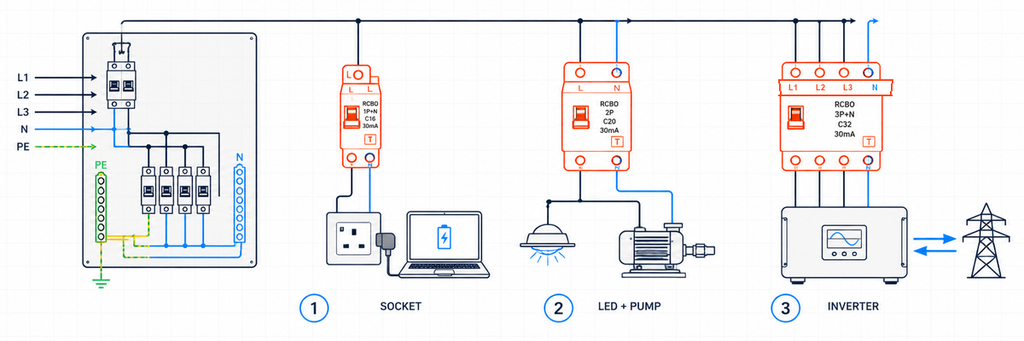
Trois circuits terminaux différents nécessitant une sélection de RCBO basée sur leur charge réelle et leur configuration de conducteursCes exemples sont illustratifs, et non des enregistrements de projets JUTRION achevés. Leur but est de montrer comment un paramètre change parce que le circuit change.
Dossier de projet 1 : Un circuit de prises de bureau
Le premier circuit alimente des prises générales dans un bureau en 230 V. Aujourd’hui, les équipements connectés comprennent ordinateurs portables, écrans, chargeurs et une imprimante. Demain, les occupants pourront brancher d’autres appareils électroniques. Le concepteur ne peut donc pas garantir que le circuit restera une charge sinusoïdale simple en AC.
Le Type A est le point de départ défendable
Le Type AC répond au courant résiduel alternatif sinusoïdal. Le Type A répond également au courant résiduel DC pulsé. L'électronique monophasée moderne contient couramment des redresseurs et des alimentations à découpage, de sorte que le Type A est normalement le point de départ le plus pratique pour un circuit de prises non spécifié.
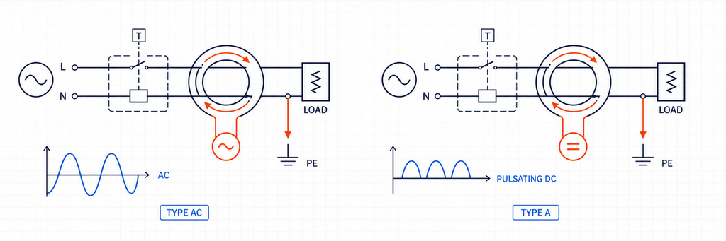
Comparaison des formes d'onde de courant résiduel entre RCBO Type AC et Type ALe Type A n'est pas un substitut universel pour chaque type de RCD. Les équipements capables de produire un DC lisse ou des courants résiduels à fréquences mixtes particulières peuvent nécessiter un Type F, un Type B ou une autre disposition déclarée. Pour un circuit de prises de bureau général, cependant, le Type A répond à une population de charges plus réaliste que le Type AC.
Pourquoi 30 mA et 20 A répondent à des questions différentes
La spécification du bureau propose un calibre de courant résiduel de 30 mA pour une protection supplémentaire selon les règles d'installation applicables. Cette valeur de 30 mA est IΔn ; elle décrit la fonction de courant résiduel. Elle ne décrit pas le courant de charge que le circuit peut transporter.
Supposons que le courant de conception calculé soit de 17,2 A et que le câble installé ait une capacité de transport de courant corrigée de 24 A. Un dispositif 20 A respecte la relation initiale de protection du conducteur :
Ib ≤ In ≤ Iz
17,2 A ≤ 20 A ≤ 24 A
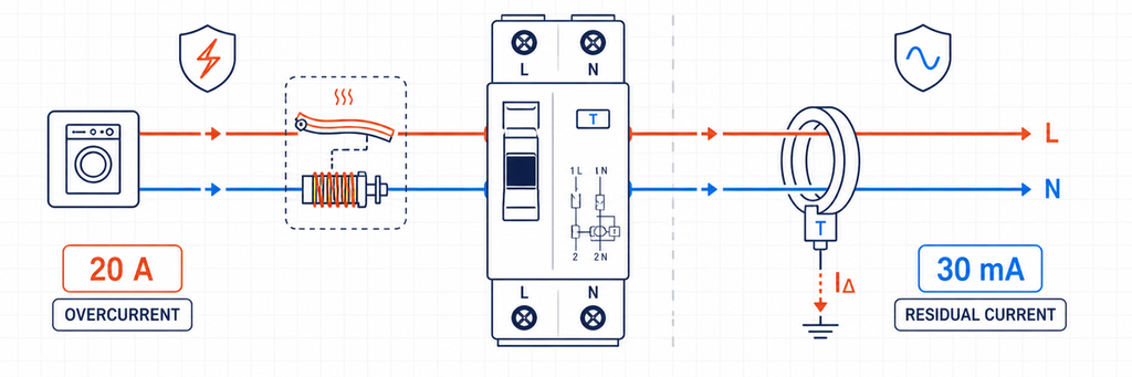
Protection contre les surintensités RCBO 20 ampères comparée à la protection contre les courants résiduels 30 milliampèresIci, Ib est le courant de conception, In est le courant nominal du RCBO et Iz est la capacité corrigée du câble. La température ambiante, le groupement, l'isolation, la méthode d'installation, les harmoniques et les règles nationales doivent déjà être reflétés dans Iz. Choisir 25 A parce que c'est la taille de catalogue suivante dépasserait la capacité déclarée du câble.
Les RCBO individuels protègent la continuité ainsi que les personnes
Si plusieurs circuits de bureau partagent un RCCB, les fuites de leurs filtres électroniques s’additionnent au niveau du dispositif partagé. Un défaut à la terre peut aussi déconnecter tous les MCB en aval. Les RCBO individuels répartissent la fuite par circuit et contiennent généralement un déclencheur différentiel sur la branche affectée. Cela facilite la localisation du défaut et réduit les pertes de service inutiles.
L'architecture n'élimine pas la planification des fuites. Le courant normal du conducteur de protection doit encore avoir une marge sous le seuil du dispositif, en particulier lorsque de nombreuses alimentations informatiques ou de longs câbles sont connectés.
Le résultat pour le bureau
230 V AC, RCBO 1P+N, 20 A, Type A, 30 mA, courbe B ou C sous réserve de vérification de l'appel et du défaut, pouvoir de coupure supérieur au niveau de défaut mesuré/calculé du tableau, compatible avec le jeu de barres déclaré du tableau de distribution.
La courbe et le pouvoir de coupure restent ouverts car aucun ne peut être choisi à partir des seules “ prises de bureau ”.
Dossier de projet 2 : Éclairage LED à côté d'une petite pompe
Le deuxième tableau contient deux circuits sortants avec un courant normal similaire. L'un alimente un groupe de drivers LED ; l'autre alimente une petite pompe à démarrage direct. Les deux peuvent produire un bref pic de courant lors de la mise sous tension, mais la source et la durée de ce pic diffèrent.
Courbe B versus courbe C est une décision liée à l'appel et au chemin de défaut
Pour les caractéristiques courantes des disjoncteurs miniatures CEI, la courbe B a généralement une plage de fonctionnement instantané autour de 3–5 fois In, tandis que la courbe C est autour de 5–10 fois In. La courbe D, souvent autour de 10–20 fois In, est réservée aux applications à appel plus élevé qui ont été spécifiquement conçues. Le fonctionnement exact doit être vérifié par rapport aux données produit applicables.
Un RCBO à courbe C peut tolérer un courant de démarrage de courte durée plus important avant que son élément magnétique ne fonctionne. Cela n'en fait pas un meilleur choix polyvalent. Le seuil plus élevé signifie également que le circuit doit fournir plus de courant de défaut pour assurer une déconnexion instantanée.
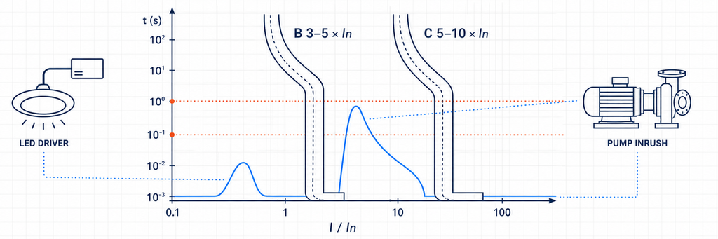
Plages de déclenchement instantané des RCBO courbe B et courbe C comparées au courant d'appel des drivers LED et de la pompe| Preuves issues du circuit | Ce que cela suggère | Ce qui doit être vérifié ensuite |
|---|---|---|
| Pic de démarrage faible ou contrôlé | La courbe B peut rester adaptée | Courbe du fabricant et événements de commutation normaux |
| Pic court et reproductible au-dessus de la zone magnétique B | Envisager la courbe C | Conditions de boucle de défaut/déconnexion et protection des câbles |
| Courant d'appel très élevé de transformateur ou de moteur | Solution C/D étudiée ou méthode de démarrage différente | Courant de défaut disponible, coordination et protection des équipements |
| Déclenchement après plusieurs minutes de fonctionnement | Probablement une surcharge thermique plutôt qu'un courant d'appel | Courant de charge, température de l'enceinte, bornes et câble |
| L'indication de déclenchement montre un fonctionnement en courant résiduel | Passer de B à C ne résoudra pas le problème | Fuite, isolation, humidité, routage du neutre et type de RCD |
Cette distinction évite une erreur fréquente de diagnostic. Un RCBO à courbe B ou C avec la même sensibilité nominale de 30 mA a la même sensibilité au courant différentiel. La lettre de courbe concerne la section surintensité ; elle ne rend pas le RCBO plus tolérant aux fuites à la terre.
Les drivers LED et moteurs de pompe modifient aussi la question du type de RCD
Les drivers LED contiennent de l'électronique, donc le Type A est une base raisonnable. Un circuit moteur monophasé conventionnel peut aussi inclure un contrôleur électronique, un démarreur progressif ou un variateur de vitesse. Une fois l'électronique de puissance introduite, les instructions de l'équipement—et non le mot “ moteur ”—déterminent si le Type A reste adapté ou si un comportement Type F/B est nécessaire.
Les deux résultats de circuit
Après avoir vérifié un courant d'appel modeste de driver LED et un courant de défaut adéquat, le circuit d'éclairage peut se terminer comme :
230 V AC, 1P+N, 16 A, Type A, 30 mA, courbe B, 6 kA lorsque le courant de défaut prospectif vérifié est inférieur à cette valeur nominale.
Si le pic de démarrage de la pompe dépasse la zone de la courbe B mais que le circuit satisfait aux exigences de coupure de la courbe C, le circuit de pompe peut être considéré comme :
230 V AC, 1P+N ou 2P selon les besoins, 16 A, Type A (ou type spécifié par l'équipement), 30 mA si requis, courbe C, pouvoir de coupure adapté au niveau de défaut du tableau.
La différence n'était pas “ éclairage versus moteur ” selon l'étiquette. C'était le comportement de démarrage mesuré ou déclaré, la forme d'onde du courant résiduel et le chemin de défaut.
Fichier de projet 3 : Un circuit triphasé alimenté par onduleur
Le troisième projet connecte un système triphasé à électronique de puissance. Il peut importer de l'énergie, exporter de l'énergie ou fonctionner différemment lorsqu'une source de secours est active. Un raccourci de catalogue tel que “ quatre pôles, Type B ” est dangereux car la conception du convertisseur et la topologie d'alimentation n'ont pas encore été établies.
Laisser la documentation du convertisseur définir le type de courant résiduel
Le type F étend le comportement du type A pour des conditions mixtes de fréquence définies associées à certaines charges d’onduleurs monophasés. Le type B couvre une plage plus large de courant différentiel, incluant le courant continu lisse selon ses caractéristiques applicables. Certains chargeurs EV et onduleurs intègrent une surveillance du courant continu résiduel ; d’autres nécessitent un dispositif particulier en amont.
Le choix ne peut pas être fait à partir de la seule catégorie de produit. Confirmer :
- la forme d'onde du courant résiduel que l'équipement peut produire ;
- si la détection du courant différentiel continu est interne ;
- l’exigence exacte du RCD/RCBO en amont dans les instructions de l’équipement ;
- la coordination avec tout dispositif de courant résiduel en amont ;
- les règles nationales pour l'application.
Ne pas confondre un RCBO type B avec un RCBO à courbe B. Le Type B décrit la capacité de détection du courant résiduel. La courbe B décrit la réponse instantanée aux surintensités. Un produit peut être Type B avec une courbe C.
Les pôles suivent les conducteurs, pas le nom de la charge
Une charge triphasée à trois fils sans neutre peut utiliser un arrangement 3P. Un système triphasé à quatre fils avec neutre nécessite 3P+N ou 4P selon la définition du produit, du système et des règles d'installation. La fiche technique doit indiquer si le neutre est coupé, solide ou protégé contre les surintensités.
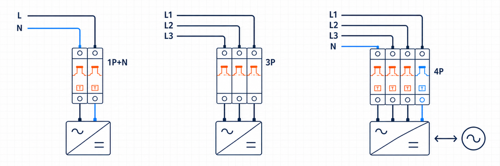
Dispositions de pôles RCBO 1P plus N, 3P et 4P pour circuits alimentés par onduleur| Agencement | Système probable | Confirmation requise |
|---|---|---|
| 1P+N | Ligne et neutre monophasés | Coupure du neutre, direction ligne/charge et position du jeu de barres |
| 2P | Monophasé avec coupure bipolaire | Quels pôles sont coupés et protégés contre les surintensités |
| 3P | Triphasé sans neutre | Aucun besoin de fonctionnement ou de détection pour le neutre |
| 3P+N | Triphasé avec neutre | Comportement de coupure/protection du neutre |
| 4P | Triphasé, quatre fils avec fonctionnement tétrapolaire déclaré | Fonctionnement simultané et compatibilité système |
Chaque conducteur requis par le dispositif de détection de courant résiduel doit suivre le schéma du fabricant. Un neutre emprunté ou contourné crée un déséquilibre et peut faire déclencher l'appareil même lorsque les charges elles-mêmes sont saines.
La puissance inverse nécessite un appareil bidirectionnel déclaré
Le solaire, les batteries et les équipements vehicle-to-grid peuvent alimenter le circuit dans le sens inverse d’une charge conventionnelle. Un interrupteur manuel ne garantit pas la compatibilité bidirectionnelle. Vérifiez la direction d’alimentation autorisée, l’orientation des bornes, la tenue au court-circuit dans chaque sens, le comportement du neutre et le système de tableau approuvé.
Le RCBO ne constitue qu'une partie de cette chaîne de protection. Il ne remplace pas l'isolation requise, les fonctions anti-îlotage, la protection contre les surtensions ou l'identification sûre de la source.
Le résultat du circuit onduleur
400 V AC, 3P/3P+N/4P selon le système de conducteurs réel, type de courant résiduel requis par le fabricant du convertisseur, sensibilité requise par les règles d'application, courbe C/D uniquement après vérification du démarrage et des défauts, usage bidirectionnel déclaré lorsque la puissance peut s'inverser, et pouvoir de coupure supérieur au niveau de défaut du projet.
Cette spécification est plus longue car le système comporte plus d'interfaces. La réduire à “ 4P C32 30 mA ” écarterait les décisions les plus susceptibles d'affecter la compatibilité.
Le décodeur de caractéristiques : ce que chaque marquage prouve
Les trois dossiers de projet peuvent maintenant être réduits à un seul tableau de décodage. Chaque caractéristique couvre un risque différent ; aucune valeur unique ne peut en remplacer une autre.
| Champ RCBO | Signification technique | Preuve du projet | Défaillance si ignoré |
|---|---|---|---|
| Tension/fréquence nominale | Conditions d'alimentation pour le fonctionnement déclaré | Schémas système et données des équipements | Fonctionnement incorrect ou caractéristique invalide |
| In (A) | Courant nominal de la section de surintensité | Ib, Iz corrigé et régime de charge | Déclenchements par surcharge ou câble non protégé |
| Courbe B/C/D | Réponse magnétique instantanée | Données de courant d'appel et de courant de défaut | Déclenchements intempestifs au démarrage ou élimination inadéquate des défauts |
| Types AC/A/F/B | Capacité de forme d'onde du courant résiduel | Topologie de charge et instructions du fabricant | Défaut de réponse correcte à la forme d'onde possible |
| IΔn (mA) | Sensibilité au courant résiduel | Objectif de protection et règle d'installation | Mauvais niveau de protection ou mauvaise continuité |
| Pôles/neutre | Conducteurs détectés, coupés et protégés | Schéma unifilaire et système de mise à la terre | Isolation, détection ou fonctionnement du neutre incorrects |
| Pouvoir de coupure (kA) | Service d'interruption de court-circuit maximal déclaré | Courant de court-circuit présumé | Appareil utilisé au-delà de sa capacité d'interruption testée |
| Interface direction/plateau | Orientation d'alimentation et compatibilité physique | Fiche technique actuelle et déclaration de la carte | Installation invalide, incompatibilité de barre omnibus ou problème de puissance inversée |
IEC 61009-1:2024 fournit les exigences produit et les tests pour les RCBO pour les usages domestiques et similaires dans son champ d'application déclaré. Cela ne remplace pas le code d'installation national. La conformité du produit répond à la question de savoir si le RCBO répond à ses exigences produit déclarées ; la conformité à l'installation répond à la question de savoir si cet appareil est correctement appliqué dans le circuit.
Pourquoi 10, 30, 100 et 300 mA ne sont pas des grades de qualité
Un IΔn plus bas est plus sensible, mais “plus sensible” ne signifie pas “meilleur pour chaque position”. Des dispositifs de dix milliampères peuvent être sélectionnés pour des tâches locales particulières ou de sensibilité plus élevée. Trente milliampères sont largement utilisés pour une protection supplémentaire sur les circuits finaux. Les valeurs de cent et 300 mA peuvent servir à des rôles sélectionnés en amont, d'équipement ou de risque d'incendie.
Un dispositif de 100 ou 300 mA en amont ne remplace pas la protection de 30 mA en aval là où 30 mA est requis. Inversement, l'installation d'une protection instantanée de 30 mA à la fois en amont et en aval peut compromettre la sélectivité car les deux dispositifs voient le même déséquilibre de courant de terre.
Lorsque la protection contre les courants résiduels en amont est utilisée, coordonnez à la fois le seuil et le temps de fonctionnement. Une fonction sélective/délai appartient au niveau autorisé par la conception de l'installation ; elle ne doit pas retarder une fonction de protection de circuit final qui doit fonctionner rapidement.
6 kA ou 10 kA est une décision de localisation
La capacité de coupure doit être au moins égale au courant de court-circuit prospectif au point d’installation du RCBO dans ses conditions déclarées. Un tableau proche d’un transformateur peut avoir un niveau de défaut plus élevé qu’un circuit final éloigné, même si le bâtiment distant est physiquement plus grand.
Utilisez un calcul, une mesure ou un enregistrement fiable du niveau de défaut du projet. Si une protection de secours en amont est proposée, utilisez une combinaison testée ou déclarée par le fabricant. Un disjoncteur en amont avec une grande capacité d'interruption ne transfère pas automatiquement cette capacité à un RCBO en aval.
La protection de secours et la sélectivité sont également différentes. Une combinaison peut interrompre un défaut élevé en toute sécurité pendant que les deux dispositifs s'ouvrent. Si la continuité nécessite uniquement la déconnexion du circuit en aval, obtenez des preuves de sélectivité pour la plage de courant pertinente.
Transformez les données du projet en une description commandable
Avant de sélectionner un modèle, assemblez un court dossier de projet :
- pays/marché et exigences d'installation applicables ;
- tension du système, fréquence et arrangement de mise à la terre ;
- conducteurs monophasés ou triphasés, y compris le neutre ;
- description de la charge, topologie du convertisseur électronique et courant de démarrage ;
- courant de conception et capacité de câble corrigée ;
- objectif de protection contre les courants résiduels requis ;
- courant de court-circuit prospectif au tableau ;
- direction du flux d'énergie dans chaque mode de fonctionnement ;
- modèle d'unité de consommation/tableau de distribution, barre omnibus et largeur de module disponible ;
- exigences en matière de bornes, environnementales, d'indication et d'accessoires.
Ensuite, rédigez la spécification en une ligne :
[voltage/frequency], [poles and neutral arrangement], [In], [curve], [Type AC/A/F/B], [IΔn], [breaking capacity], [supply direction], [product standard/market approval], [board and busbar interface].
Cette ligne est plus utile que de demander à un fournisseur “un bon RCBO.” Elle donne aux équipes d'ingénierie et d'achat la même référence et expose les informations manquantes avant que des échantillons ou une production ne soient engagés.
Valider le RCBO sélectionné dans le tableau réel
Un ensemble de notation techniquement correct peut encore échouer à l'interface d'assemblage. Avant qu'un distributeur n'accepte une gamme de remplacement ou qu'un OEM ne libère une unité de consommation, le RCBO sélectionné doit être vérifié dans l'enceinte prévue avec la barre omnibus, les conducteurs et les accessoires prévus.
Ajustement mécanique et câblage
Confirmer la largeur du module, l'engagement sur rail DIN, la position des dents de la barre omnibus, l'emplacement du neutre et l'accès aux bornes. Un dispositif décrit comme 1P+N peut utiliser un fil neutre volant, une borne neutre sur un côté particulier ou un pas de barre omnibus différent d'un autre dispositif 1P+N. Des dimensions avant similaires ne prouvent pas l'interchangeabilité.
Vérifiez le matériau des conducteurs autorisés, la section rigide/flexible et les exigences en matière de manchons. Préparez les conducteurs comme déclaré et appliquez le couple de serrage spécifié. Une connexion lâche peut créer de la chaleur sans dépasser le courant de charge du circuit, tandis qu'un couple excessif peut endommager la borne ou le conducteur.
Preuve fonctionnelle
La mise en service doit distinguer les deux systèmes de déclenchement. Lorsque le dispositif fournit une indication séparée, enregistrez si une opération de test est rapportée comme courant résiduel ou surintensité. Vérifiez la fonction du bouton de test dans les conditions d'alimentation indiquées par le fabricant, puis complétez les tests d'installation requis par les règles applicables. Le bouton de test vérifie un chemin fonctionnel interne ; il ne mesure pas la boucle de défaut à la terre complète, l'état d'isolation ou chaque exigence de temps de déclenchement.
Pour les circuits avec de nombreuses charges électroniques, enregistrez le courant de charge normal, le pic de démarrage et la fuite résiduelle après la mise en service. Ces trois valeurs créent une base de référence. Si des déclenchements apparaissent des mois plus tard, la maintenance peut comparer les nouvelles preuves avec l'état d'origine plutôt que de remplacer les dispositifs par essais et erreurs.
Température et regroupement
Plusieurs dispositifs modulaires chargés montés côte à côte peuvent fonctionner dans un environnement local plus chaud que ne le suggère la température ambiante. La ventilation de l'enceinte, les composants adjacents produisant de la chaleur, la taille des conducteurs et la charge soutenue affectent tous la température. Appliquez les instructions de réduction de puissance ou d'espacement du fabricant lorsque cela est pertinent ; ne répondez pas à un déclenchement thermique en augmentant la capacité en ampères sans vérifier à nouveau la protection des câbles.
Contrôle des lots et de la documentation
Pour un OEM ou un distributeur, verrouillez les attributs approuvés dans la nomenclature : modèle exact, courbe, type de courant résiduel, IΔn, pôles, capacité de coupure, disposition des bornes, approbation et accessoires compatibles. Un substitut qui ne correspond qu'au courant et à la largeur peut silencieusement changer le type de forme d'onde ou le comportement du neutre.
Conservez la fiche technique actuelle, les documents de déclaration/certification requis par le marché cible, le schéma de câblage et l'identification du lot avec l'enregistrement de l'échantillon approuvé. Cela transforme la sélection en un contrôle de production répétable plutôt qu'une conversation d'ingénierie ponctuelle.
Séparer la conformité du produit de la conformité à l'installation
Un marquage IEC est important, mais il ne décide pas où ou comment le RCBO peut être installé. IEC 61009-1:2024 définit les exigences générales et les essais pour les RCBO destinés aux usages domestiques et similaires dans son champ d'application déclaré. Les règles nationales de câblage, la réglementation locale, les spécifications du projet et l'autorité compétente déterminent l'application d'installation.
| Question | D'où vient la réponse | Exemple |
|---|---|---|
| Le RCBO a-t-il été évalué en tant que produit ? | Norme produit, certification et documentation du fabricant | Tension déclarée, courant, IΔn, type et capacité de court-circuit |
| La protection contre les courants résiduels est-elle requise ici ? | Règles d'installation nationales et conception de projet | Prise, circuit extérieur, emplacement humide ou équipement spécial |
| Quel type de courant résiduel est autorisé ? | Règles d'installation plus instructions d'équipement | Restriction sur le type AC ou exigence créée par l'équipement de conversion |
| Le circuit se déconnectera-t-il à temps ? | Calcul/test d'installation et caractéristique de l'appareil | Conditions de boucle de défaut pour une courbe B/C/D choisie |
| L'RCBO peut-il s'adapter à ce tableau ? | Déclarations du système de tableau et du fabricant de l'appareil | Barres omnibus, bornes, position neutre et classification de l'armoire |
Cette distinction est importante dans les projets d'exportation. Une configuration de produit acceptée dans un marché peut nécessiter un type de courant résiduel différent, un agencement de pôles, un marquage d'approbation ou un système de tableau de distribution dans un autre. Ne convertissez pas une règle nationale en une revendication universelle IEC, et ne supposez pas qu'un certificat de composant approuve le panneau complet.
La Guide de sélection des RCD BEAMA est une source autoritaire utile pour le raisonnement sur les formes d'onde et les applications, en particulier autour des charges électroniques modernes. Ses références d'installation régionales doivent encore être appliquées dans leur propre juridiction. Pour un autre marché, utilisez les règles nationales pertinentes et les instructions d'équipement.
Où un RCBO s'adapte-t-il — et où ne s'adapte-t-il pas
Un RCBO combine la protection contre les courants résiduels avec la protection contre les surcharges et les courts-circuits. Un RCCB nécessite normalement une protection contre les surintensités coordonnée, tandis qu'un MCB ne fournit pas de protection contre les courants résiduels. L'architecture RCBO-par-circuit améliore souvent la continuité et l'isolement des défauts, mais elle doit toujours être coordonnée avec la protection en amont et le tableau de distribution.
Un RCBO ne reconnaît normalement pas les signatures d'arc dangereuses. Si l'atténuation des défauts d'arc fait partie du projet, utilisez le guide AFDD de JUTRION pour cartographier les fonctions de protection requises. Les RCBO ne remplacent pas non plus les SPD, les sectionneurs ou la protection spécifique aux équipements simplement parce que plusieurs fonctions partagent un même boîtier.
Choisissez la fonction de protection avant le numéro de catalogue
Le circuit de bureau a commencé avec des charges électroniques imprévisibles, donc le Type A et la protection individuelle 30 mA ont contrôlé la décision. Les circuits d'éclairage et de pompe ont commencé avec un comportement de démarrage, donc le choix de la courbe B/C dépendait à la fois du courant d'appel et du courant de défaut. Le circuit onduleur a commencé avec la forme d'onde, la topologie des conducteurs et la puissance inverse, donc les instructions de l'équipement et l'approbation bidirectionnelle comptaient avant l'ampérage.
Voici la règle de sélection transférable : identifiez le défaut que l'RCBO doit détecter, prouvez le câble et le chemin de défaut, puis complétez l'interface physique. Un numéro de catalogue correct est le résultat de ce processus, pas le point de départ.
JUTRION propose RCBO pour distribution monophasée et triphasée avec plusieurs combinaisons de pôles, de courant, de sensibilité, de type de forme d'onde, de courbe et de capacité de coupure. Partagez l'enregistrement du projet ci-dessus lors de la demande de support à la sélection afin que le modèle proposé puisse être vérifié par rapport au circuit réel.
Questions fréquemment posées
Dois-je choisir un RCBO de type A ou de type AC ?
Le Type AC détecte le courant résiduel alternatif sinusoïdal, tandis que le Type A détecte également le courant résiduel continu pulsé. Parce que de nombreux appareils modernes contiennent des redresseurs et des alimentations à découpage, le Type A est souvent le point de départ le plus pratique pour les circuits généraux de prises, d'éclairage et d'appareils. Le choix final doit toujours suivre les instructions de l'équipement connecté et les règles d'installation applicables.
Un RCBO de 30 mA est-il toujours le bon choix ?
Non. Une valeur de courant résiduel de 30 mA est couramment utilisée là où une protection supplémentaire est requise, mais ce n'est pas une valeur universelle pour chaque circuit. Les règles d'application, le courant de fuite prévu, la sélectivité en amont et les exigences de l'équipement doivent être vérifiés. La valeur de 30 mA ne détermine également pas la capacité de courant de charge du RCBO.
Quelle est la différence entre un RCBO de type B et un RCBO à courbe B ?
Ils décrivent des fonctions différentes. Le Type B identifie la capacité de détection du courant résiduel, y compris le continu lisse dans les caractéristiques déclarées de l'appareil. La courbe B identifie la plage de fonctionnement instantané de la section de surintensité. Un RCBO peut donc avoir un comportement de courant résiduel de Type B et une caractéristique de surintensité en courbe C.
Quand devrais-je choisir un RCBO à courbe C plutôt qu'à courbe B ?
Considérez la courbe C lorsque le courant de démarrage vérifié provenant d'équipements tels que des moteurs, des transformateurs ou des groupes de pilotes LED peut entrer dans la zone de fonctionnement magnétique de la courbe B. La courbe C n'est pas un remède automatique contre les déclenchements intempestifs : le circuit doit toujours fournir suffisamment de courant de défaut pour le temps de déconnexion requis, et l'indication de déclenchement doit d'abord confirmer que l'événement est une surintensité plutôt qu'un courant résiduel.
Ai-je besoin d'un RCBO 1P+N, 2P, 3P ou 4P ?
Choisissez l'agencement des pôles en fonction des conducteurs d'alimentation réels et de la méthode de déconnexion requise. Un circuit monophasé ligne et neutre peut utiliser 1P+N ou 2P selon le produit et la conception de l'installation. Les circuits triphasés peuvent nécessiter 3P, 3P+N ou 4P selon la présence d'un neutre et comment il doit être commuté et détecté. Suivez toujours le schéma de câblage du fabricant.
Puis-je utiliser un RCBO de type A standard avec un onduleur ?
Seulement lorsque le fabricant de l'onduleur et les règles d'installation applicables le permettent. Les équipements électroniques de puissance peuvent nécessiter un type A, un type F, un type B ou un agencement coordonné avec une surveillance intégrée du courant continu résiduel. Vérifiez également la configuration des pôles, le traitement du neutre, la direction d'alimentation autorisée et le fonctionnement bidirectionnel déclaré lorsque l'énergie peut revenir vers le réseau.
Références techniques
