

RCBO Selection Guide for Real Circuits: Type A/AC, 30mA, B/C Curves, and Poles
A request for “32 A, 30 mA RCBO” is not ready for ordering. It identifies a load-current class and a residual-current threshold, but it does not identify the fault waveform, starting current, cable limit, supply conductors or available short-circuit current. The same two numbers could describe a general socket circuit, a bank of LED drivers or an inverter feeder—and those circuits may need different RCBOs.
The practical answer is to choose the RCBO around the protection job. For a typical modern final circuit, Type A and 30 mA are often the starting point. The finished choice still depends on whether the load produces electronic leakage, whether B curve can tolerate startup, which conductors must be disconnected and whether 6 kA is sufficient at the board.
This guide follows three project files rather than a catalogue sequence. Each project starts with a different risk, then ends with a complete RCBO description that a contractor, panel builder or distributor can actually use.
Three Circuits That Should Not Receive the Same RCBO
| Project file | Main uncertainty | Likely starting point | Decision that controls the result |
|---|---|---|---|
| Office socket circuit | Future electronic loads and continuity | Type A, 30 mA, individual RCBO | Cable rating, fault level and board interface |
| LED lighting and small pump panel | Short startup current | Type A, 30 mA, B or C curve | Measured/declared inrush versus fault-disconnection conditions |
| Inverter-backed three-phase circuit | Residual-current waveform, reverse power and neutral | Equipment-defined Type A/F/B and 3P/3P+N/4P | Converter instructions, supply topology and bidirectional approval |
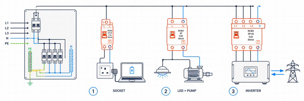
Three different final circuits requiring RCBO selection based on their actual load and conductor arrangementThese examples are illustrative, not records of completed JUTRION projects. Their purpose is to show how one parameter changes because the circuit changes.
Project File 1: An Office Socket Circuit
The first circuit supplies general socket outlets in a 230 V office. Today the connected equipment includes laptops, monitors, chargers and a printer. Tomorrow the occupants may connect different electronic appliances. The designer therefore cannot prove that the circuit will remain a simple sinusoidal AC load.
Type A is the defensible starting point
Type AC responds to sinusoidal alternating residual current. Type A also responds to pulsating DC residual current. Modern single-phase electronics commonly contain rectifiers and switched-mode power supplies, so Type A is normally the more practical starting point for an unspecified socket circuit.
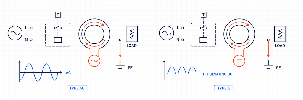
Type AC and Type A RCBO residual-current waveform comparisonType A is not a universal substitute for every RCD type. Equipment capable of producing smooth DC or particular mixed-frequency residual currents may require Type F, Type B or another declared arrangement. For a general office socket circuit, however, Type A addresses a more realistic load population than Type AC.
Why 30 mA and 20 A answer different questions
The office specification proposes a 30 mA residual-current rating for additional protection under the applicable installation rules. That 30 mA value is IΔn; it describes the residual-current function. It does not describe the load current the circuit can carry.
Assume the calculated design current is 17.2 A and the installed cable has a corrected current-carrying capacity of 24 A. A 20 A device passes the initial conductor-protection relationship:
Ib ≤ In ≤ Iz
17.2 A ≤ 20 A ≤ 24 A
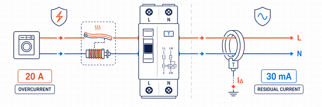
RCBO 20 amp overcurrent protection compared with 30 milliamp residual-current protectionHere, Ib is design current, In is RCBO rated current and Iz is corrected cable capacity. Ambient temperature, grouping, insulation, installation method, harmonics and national rules must already be reflected in Iz. Choosing 25 A because it is the next catalogue size would exceed the stated cable capacity.
Individual RCBOs protect continuity as well as people
If several office circuits share one RCCB, leakage from their electronic filters accumulates at the shared device. One earth-fault event may also disconnect every downstream MCB. Individual RCBOs divide the leakage by circuit and usually contain a residual-current trip to the affected branch. That makes fault location easier and reduces unnecessary loss of service.
The architecture does not eliminate leakage planning. Normal protective-conductor current still needs margin below the device threshold, particularly where many IT power supplies or long cables are connected.
The office result
230 V AC, 1P+N RCBO, 20 A, Type A, 30 mA, B or C curve subject to inrush and fault verification, breaking capacity above the measured/calculated board fault level, compatible with the declared consumer-unit busbar.
The curve and breaking capacity remain open because neither can be chosen from “office sockets” alone.
Project File 2: LED Lighting Beside a Small Pump
The second panel contains two outgoing circuits with similar normal current. One feeds a group of LED drivers; the other feeds a small direct-on-line pump. Both can produce a brief current peak during energization, but the source and duration of that peak differ.
B curve versus C curve is an inrush and fault-path decision
For common IEC miniature-breaker characteristics, B curve typically has an instantaneous operating range around 3–5 times In, while C curve is around 5–10 times In. D curve, often around 10–20 times In, is reserved for higher-inrush duties that have been specifically engineered. Exact operation must be checked against the applicable product data.
A C-curve RCBO can tolerate a larger short-duration startup current before its magnetic element operates. That does not make it a better general-purpose choice. The higher threshold also means the circuit must deliver more fault current to ensure instantaneous disconnection.
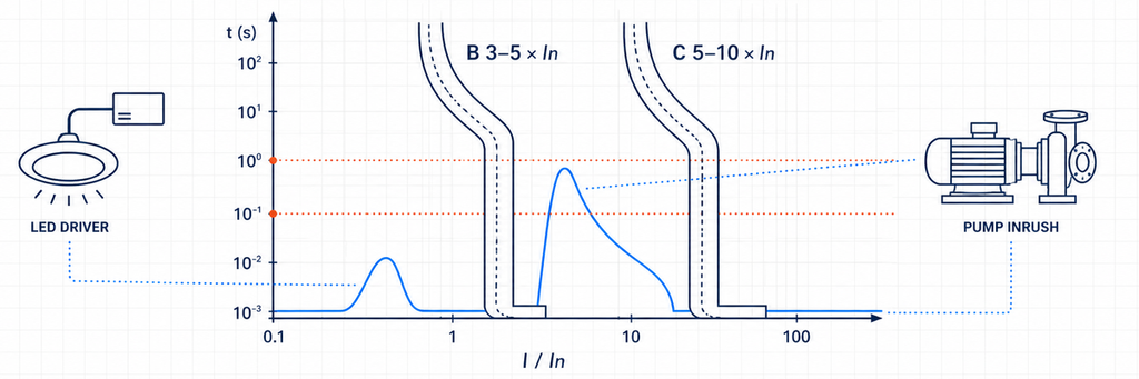
B-curve and C-curve RCBO instantaneous trip ranges compared with LED-driver and pump inrush current| Evidence from the circuit | What it suggests | What must be verified next |
|---|---|---|
| Low or controlled startup peak | B curve may remain suitable | Manufacturer curve and normal switching events |
| Short, repeatable peak above the B magnetic region | Consider C curve | Fault-loop/disconnection conditions and cable protection |
| Very high transformer or motor inrush | Engineered C/D solution or different starting method | Available fault current, coordination and equipment protection |
| Trip occurs after running for minutes | Likely thermal overload rather than inrush | Load current, enclosure temperature, terminals and cable |
| Trip indication shows residual-current operation | Changing B to C will not solve it | Leakage, insulation, moisture, neutral routing and RCD type |
This distinction prevents a common diagnosis error. A B-curve and C-curve RCBO with the same 30 mA marking have the same nominal residual-current sensitivity. The curve letter belongs to the overcurrent section; it does not make the RCBO more tolerant of earth leakage.
LED drivers and pump motors also change the RCD-type question
LED drivers contain electronics, so Type A is a sensible baseline. A conventional single-phase motor circuit may also include an electronic controller, soft starter or variable-speed drive. Once power electronics are introduced, the equipment instructions—not the word “motor”—determine whether Type A remains suitable or whether Type F/B behavior is needed.
The two circuit results
After verifying a modest LED-driver inrush and adequate fault current, the lighting circuit may finish as:
230 V AC, 1P+N, 16 A, Type A, 30 mA, B curve, 6 kA where the verified prospective fault current is below that rating.
If the pump starting record exceeds the B-curve region but the circuit satisfies C-curve disconnection requirements, the pump circuit may finish as:
230 V AC, 1P+N or 2P as required, 16 A, Type A (or equipment-specified type), 30 mA where required, C curve, breaking capacity matched to the board fault level.
The difference was not “lighting versus motor” by label. It was the measured or declared startup behavior, residual-current waveform and fault path.
Project File 3: An Inverter-Backed Three-Phase Circuit
The third project connects a three-phase power-electronic system. It may import power, export power or operate differently when a backup source is active. A catalogue shortcut such as “four-pole, Type B” is unsafe because the converter design and supply topology have not yet been established.
Let the converter documentation define the residual-current type
Type F extends Type A behavior for defined mixed-frequency conditions associated with selected single-phase inverter loads. Type B covers a wider residual-current range, including smooth DC under its applicable characteristics. Some EV chargers and inverters incorporate residual direct-current monitoring; others require a particular upstream device.
The choice cannot be made from product category alone. Confirm:
- the residual-current waveform the equipment can produce;
- whether DC residual-current detection is internal;
- the exact upstream RCD/RCBO requirement in the equipment instructions;
- coordination with any upstream residual-current device;
- national rules for the application.
Do not confuse a Type B RCBO with a B-curve RCBO. Type B describes the residual-current sensing capability. B curve describes the instantaneous overcurrent response. A product can be Type B with a C curve.
Poles follow the conductors, not the load name
A three-phase, three-wire load without neutral may use a 3P arrangement. A three-phase, four-wire system with neutral requires 3P+N or 4P as defined by the product, system and installation rules. The datasheet must show whether neutral is switched, solid or protected against overcurrent.
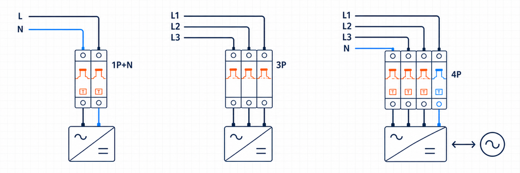
RCBO 1P plus N, 3P and 4P pole arrangements for inverter-backed circuits| Arrangement | Likely system | Required confirmation |
|---|---|---|
| 1P+N | Single-phase line and neutral | Neutral switching, line/load direction and busbar position |
| 2P | Single-phase with two-pole disconnection | Which poles are switched and overcurrent-protected |
| 3P | Three-phase without neutral | No operating or sensing need for neutral |
| 3P+N | Three-phase with neutral | Neutral switching/protection behavior |
| 4P | Three-phase, four-wire with declared four-pole operation | Simultaneous operation and system compatibility |
Every conductor required by the residual-current sensing arrangement must follow the manufacturer’s diagram. A borrowed or bypassed neutral creates imbalance and can make the device trip even when the loads themselves are healthy.
Reverse power requires a declared bidirectional device
Solar, batteries and vehicle-to-grid equipment can feed the circuit in the opposite direction from a conventional load. A manual toggle does not prove bidirectional suitability. Verify permitted supply direction, terminal orientation, short-circuit performance in each direction, neutral behavior and the approved board system.
The RCBO is only one part of this protection chain. It does not replace required isolation, anti-islanding functions, surge protection or safe source identification.
The inverter-circuit result
400 V AC, 3P/3P+N/4P according to the actual conductor system, residual-current type required by the converter manufacturer, sensitivity required by the application rules, C/D curve only after startup and fault verification, declared bidirectional use where power can reverse, and breaking capacity above the project fault level.
This specification is longer because the system carries more interfaces. Shortening it to “4P C32 30 mA” would discard the decisions most likely to affect compatibility.
The Ratings Decoder: What Each Marking Proves
The three project files can now be reduced to one decoding table. Each rating closes a different risk; no single value can stand in for another.
| RCBO field | Engineering meaning | Project evidence | Failure if ignored |
|---|---|---|---|
| Rated voltage/frequency | Supply conditions for declared operation | System drawings and equipment data | Incorrect operation or invalid rating |
| In (A) | Rated current of overcurrent section | Ib, corrected Iz and load duty | Overload trips or unprotected cable |
| B/C/D curve | Instantaneous magnetic response | Inrush and fault-current data | Nuisance startup trips or inadequate fault clearing |
| Type AC/A/F/B | Residual-current waveform capability | Load topology and manufacturer instructions | Failure to respond correctly to the possible waveform |
| IΔn (mA) | Residual-current sensitivity | Protection objective and installation rule | Wrong protection level or poor continuity |
| Poles/neutral | Conductors sensed, switched and protected | Single-line diagram and earthing system | Incorrect isolation, sensing or neutral operation |
| Breaking capacity (kA) | Maximum declared short-circuit interruption duty | Prospective short-circuit current | Device used beyond its tested interruption capability |
| Direction/board interface | Supply orientation and physical compatibility | Current datasheet and board declaration | Invalid installation, busbar mismatch or reverse-power issue |
IEC 61009-1:2024 gives product requirements and tests for RCBOs for household and similar uses within its stated scope. It does not replace the national installation code. Product conformity answers whether the RCBO meets its declared product requirements; installation compliance answers whether that device is correctly applied in the circuit.
Why 10, 30, 100 and 300 mA Are Not Quality Grades
A lower IΔn is more sensitive, but “more sensitive” does not mean “better for every position.” Ten milliampere devices may be selected for particular local or higher-sensitivity duties. Thirty milliamperes is widely used for additional protection on final circuits. One hundred and 300 mA values can serve selected upstream, equipment or fire-risk roles.
An upstream 100 or 300 mA device does not replace downstream 30 mA protection where 30 mA is required. Conversely, installing instantaneous 30 mA protection at both upstream and downstream levels can undermine selectivity because both devices see the same earth-fault imbalance.
Where upstream residual-current protection is used, coordinate both threshold and operating time. A selective/time-delayed function belongs at the level allowed by the installation design; it must not delay a final-circuit protective function that is required to operate promptly.
6 kA or 10 kA Is a Location Decision
Breaking capacity must be at least the prospective short-circuit current at the RCBO’s installation point under its declared conditions. A board near a transformer can have a higher fault level than a distant final circuit, even when the distant building is physically larger.
Use a calculation, measurement or reliable project fault-level record. If upstream backup protection is proposed, use a tested or declared manufacturer combination. An upstream breaker with a large interruption rating does not automatically transfer that rating to a downstream RCBO.
Backup protection and selectivity are also different. A combination may interrupt a high fault safely while both devices open. If continuity requires only the downstream circuit to disconnect, obtain selectivity evidence for the relevant current range.
Turn Project Data into an Orderable Description
Before selecting a model, assemble one short project record:
- country/market and applicable installation requirements;
- system voltage, frequency and earthing arrangement;
- single-phase or three-phase conductors, including neutral;
- load description, electronic converter topology and startup current;
- design current and corrected cable capacity;
- required residual-current protection objective;
- prospective short-circuit current at the board;
- power-flow direction in every operating mode;
- consumer-unit/distribution-board model, busbar and available module width;
- terminal, environmental, indication and accessory requirements.
Then write the specification in one line:
[voltage/frequency], [poles and neutral arrangement], [In], [curve], [Type AC/A/F/B], [IΔn], [breaking capacity], [supply direction], [product standard/market approval], [board and busbar interface].
This line is more useful than asking a supplier for “a good RCBO.” It gives engineering and purchasing teams the same reference and exposes missing information before samples or production are committed.
Validate the Selected RCBO in the Actual Board
A technically correct rating set can still fail at the assembly interface. Before a distributor accepts a replacement range or an OEM releases a consumer unit, the selected RCBO should be checked in the intended enclosure with the intended busbar, conductors and accessories.
Mechanical and wiring fit
Confirm module width, DIN-rail engagement, busbar tooth position, neutral location and terminal access. A device described as 1P+N may use a flying neutral lead, a neutral terminal on a particular side or a different busbar pitch from another 1P+N device. Similar front dimensions do not prove interchangeability.
Check the permitted conductor material, rigid/flexible cross-section and ferrule requirements. Prepare conductors as declared and apply the specified terminal torque. A loose connection can create heat without exceeding the circuit load current, while excessive torque can damage the terminal or conductor.
Functional evidence
Commissioning should distinguish the two trip systems. Where the device provides separate indication, record whether a test operation is reported as residual-current or overcurrent. Verify the test-button function under the supply conditions stated by the manufacturer, then complete the installation tests required by the applicable rules. The test button checks an internal functional path; it does not measure the complete earth-fault loop, insulation condition or every trip-time requirement.
For circuits with many electronic loads, record normal load current, startup peak and standing leakage after commissioning. Those three values create a baseline. If trips appear months later, maintenance can compare new evidence with the original condition rather than replacing devices by trial and error.
Temperature and grouping
Several loaded modular devices mounted side by side can operate in a warmer local environment than the room temperature suggests. Enclosure ventilation, adjacent heat-producing components, conductor size and sustained loading all affect temperature. Apply the manufacturer’s derating or spacing instructions where relevant; do not respond to a thermal trip by increasing the ampere rating without rechecking cable protection.
Batch and documentation control
For an OEM or distributor, lock the approved attributes into the bill of materials: exact model, curve, residual-current type, IΔn, poles, breaking capacity, terminal arrangement, approval and compatible accessories. A substitute that matches only current and width can silently change the waveform type or neutral behavior.
Retain the current datasheet, declaration/certification documents required by the target market, wiring diagram and lot identification with the approved sample record. This turns selection into a repeatable production control rather than a one-time engineering conversation.
Separate Product Compliance from Installation Compliance
An IEC marking is important, but it does not decide where or how the RCBO may be installed. IEC 61009-1:2024 defines general requirements and tests for RCBOs for household and similar uses within its stated scope. National wiring rules, local regulation, project specifications and the authority having jurisdiction determine the installation application.
| Question | Where the answer comes from | Example |
|---|---|---|
| Was the RCBO evaluated as a product? | Product standard, certification and manufacturer documentation | Declared voltage, current, IΔn, type and short-circuit capacity |
| Is residual-current protection required here? | National installation rules and project design | Socket, outdoor, wet-location or special-equipment circuit |
| Which residual-current type is permitted? | Installation rules plus equipment instructions | Restriction on Type AC or requirement created by converter equipment |
| Will the circuit disconnect in time? | Installation calculation/test and device characteristic | Fault-loop conditions for a chosen B/C/D curve |
| Can the RCBO fit this board? | Board-system and device-manufacturer declarations | Busbar, terminals, neutral position and enclosure rating |
This distinction matters in export projects. A product configuration accepted in one market may require a different residual-current type, pole arrangement, approval mark or distribution-board system in another. Do not convert a national rule into a universal IEC claim, and do not assume that a component certificate approves the completed panel.
The BEAMA RCD selection guide is a useful authoritative source for waveform and application reasoning, particularly around modern electronic loads. Its regional installation references still need to be applied within their own jurisdiction. For another market, use the relevant national rules and equipment instructions.
Where an RCBO Fits—and Where It Does Not
An RCBO combines residual-current protection with overload and short-circuit protection. An RCCB normally requires coordinated overcurrent protection, while an MCB does not provide residual-current protection. The RCBO-per-circuit architecture often improves continuity and fault isolation, but it must still coordinate with upstream protection and the distribution board.
An RCBO does not normally recognize hazardous arc signatures. If arc-fault mitigation is part of the project, use the JUTRION AFDD guide to map the required protection functions. RCBOs also do not replace SPDs, isolators or equipment-specific protection simply because several functions share one enclosure.
Choose the Protection Job Before the Catalogue Number
The office circuit began with unpredictable electronic loads, so Type A and individual 30 mA protection controlled the decision. The lighting and pump circuits began with startup behavior, so the B/C curve choice depended on both inrush and fault current. The inverter circuit began with waveform, conductor topology and reverse power, so equipment instructions and bidirectional approval mattered before amperage.
That is the transferable selection rule: identify the fault the RCBO must detect, prove the cable and fault path, then complete the physical interface. A correct catalogue number is the output of that process, not the starting point.
JUTRION offers RCBOs for single-phase and three-phase distribution with multiple pole, current, sensitivity, waveform-type, curve and breaking-capacity combinations. Share the project record above when requesting selection support so the proposed model can be checked against the real circuit.
Frequently Asked Questions
Should I choose a Type A or Type AC RCBO?
Type AC detects sinusoidal alternating residual current, while Type A also detects pulsating DC residual current. Because many modern appliances contain rectifiers and switched-mode power supplies, Type A is often the more practical starting point for general socket, lighting and appliance circuits. The final choice must still follow the connected-equipment instructions and applicable installation rules.
Is a 30 mA RCBO always the correct choice?
No. A 30 mA residual-current rating is commonly used where additional protection is required, but it is not a universal value for every circuit. The application rules, expected standing leakage, upstream selectivity and equipment requirements must be checked. The 30 mA value also does not determine the RCBO load-current rating.
What is the difference between a Type B RCBO and a B-curve RCBO?
They describe different functions. Type B identifies residual-current detection capability, including smooth DC within the device’s declared characteristics. B curve identifies the instantaneous operating range of the overcurrent section. An RCBO can therefore have Type B residual-current behavior and a C-curve overcurrent characteristic.
When should I choose a C-curve RCBO instead of B curve?
Consider C curve when verified startup current from equipment such as motors, transformers or groups of LED drivers may enter the B-curve magnetic operating region. C curve is not an automatic cure for nuisance tripping: the circuit must still provide enough fault current for the required disconnection time, and the trip indication should first confirm that the event is overcurrent rather than residual current.
Do I need a 1P+N, 2P, 3P or 4P RCBO?
Choose the pole arrangement from the actual supply conductors and required disconnection method. A single-phase line-and-neutral circuit may use 1P+N or 2P according to the product and installation design. Three-phase circuits may require 3P, 3P+N or 4P depending on whether a neutral is present and how it must be switched and sensed. Always follow the manufacturer’s wiring diagram.
Can I use a standard Type A RCBO with an inverter?
Only when the inverter manufacturer and applicable installation rules permit it. Power-electronic equipment may require Type A, Type F, Type B or an arrangement coordinated with built-in residual direct-current monitoring. Also verify pole configuration, neutral treatment, permitted supply direction and declared bidirectional operation where power can flow back toward the grid.
Technical References
