

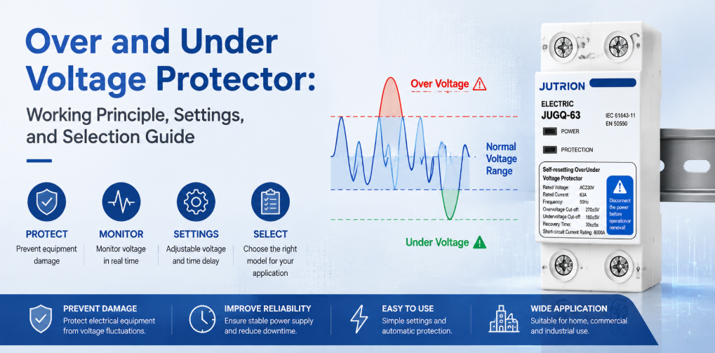
과전압 및 저전압 보호기 작동 원리 및 선정 가이드빠른 답변: 과전압 및 저전압 보호기는 어떤 역할을 하나요?
과전압 및 저전압 보호기는 공급 전압이 선택된 한계보다 높거나 낮게 유지될 때 회로를 차단하고, 전압이 회복되고 사전 설정된 지연 시간이 경과한 후 다시 연결합니다. 지속적인 과전압, 저전압 및 브라운아웃으로부터 보호합니다. 과도 서지에 대한 SPD, 과전류에 대한 회로 차단기, 누전에 대한 RCD, 또는 지속적인 전압 보정이 필요할 때 AVR을 대체하지는 않습니다.
“전압 보호”는 종종 하나의 주제로 다루어지지만, 배전반은 근본적으로 다른 여러 사건에 직면할 수 있습니다. 낙뢰로 인한 과도 현상은 마이크로초 동안 지속될 수 있습니다. 전력 회사의 전압 조정 문제나 잘못 탭된 변압기는 공급 전압을 정상 범위보다 높게 수 분간 유지할 수 있습니다. 과부하된 피더는 긴 브라운아웃을 일으킬 수 있습니다. 느슨하거나 개방된 중성선은 3상 4선식 시스템의 일부 단상 부하를 정격 전압보다 훨씬 높게 구동하는 동시에 다른 부하는 그 아래로 떨어뜨릴 수 있습니다.
어떤 단일 장치도 이러한 모든 조건을 처리하지 못합니다. 서지 보호 장치는 짧고 높은 에너지의 과도 현상을 제한합니다. 과전압 및 저전압 보호기는 RMS 공급 전압이 허용 한계를 벗어나 있을 때 부하를 차단합니다. 차단기는 과부하 및 단락 전류를 차단합니다. RCD 또는 RCBO는 잔류 전류에 반응합니다. 따라서 첫 번째 선정 규칙은 정격 전류나 디스플레이 유형이 아니라 장치를 외란에 맞추는 것입니다.
배전반 제작자나 유통업체에게 유용한 질문은 따라서 “전압 보호”가 있는지 여부가 아닙니다. 유용한 질문은 각 외란에 정의된 감지 방식, 스위칭 응답 및 복구 규칙이 있는지 여부입니다.
보호 경계: 각 전압 문제를 올바른 장치에 맞추기
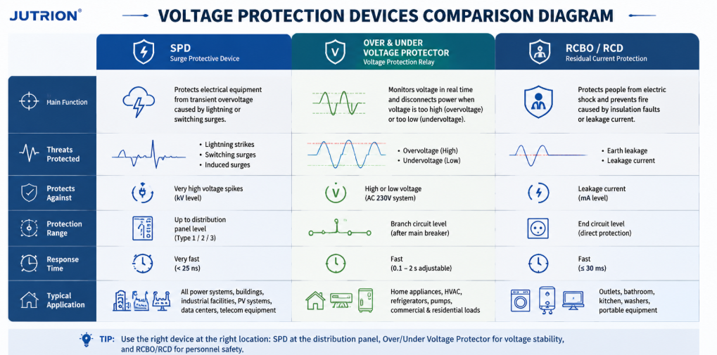
SPD, 과전압 저전압 보호기, RCBO RCD 기능을 보여주는 전압 보호 장치 비교 다이어그램| 외란 | 일반적인 지속 시간 | 1차 응답 | 일반적으로 담당하는 장치 |
|---|---|---|---|
| 낙뢰 또는 스위칭 서지 | 마이크로초에서 밀리초 | 과도 에너지를 클램프하고 우회 | 서지 보호 장치 (SPD) |
| 지속적인 과전압 | 수 초, 수 분 또는 그 이상 | 영향을 받는 부하 차단 | 과전압 보호기 또는 전압 모니터링 릴레이 |
| 저전압 또는 브라운아웃 | 수 초, 수 분 또는 그 이상 | 장비가 과열, 정지 또는 오작동하기 전에 차단 | 저전압 보호기 또는 전압 모니터링 릴레이 |
| 과부하 또는 단락 | 고장 크기에 따라 다름 | 과도한 전류 차단 | 배선용 차단기 (MCB) 또는 배선용 누전 차단기 (MCCB) |
| 누전 | 밀리초에서 지속적 | 잔류 전류를 감지하고 차단 | 누전 차단기 (RCCB) 또는 누전 겸용 배선 차단기 (RCBO) |
| 지속적인 보정이 필요한 전압 변동 | 연속적 또는 반복적 | 전압을 승압, 강압 또는 조정 | 전압 안정기 또는 AVR |
잘 설계된 배전반은 서로 다른 시간 척도에서 작동하고 서로 다른 전기적 양을 관찰하기 때문에 이러한 장치 중 여러 개를 포함할 수 있습니다. SPD를 설치한다고 해서 지속적인 과전압 보호가 불필요해지는 것은 아닙니다. 전압 보호기를 추가한다고 해서 소형 회로 차단기의 차단 용량이 증가하는 것은 아닙니다. 올바른 협조는 경쟁적이 아니라 부가적입니다.
회로 차단기가 나쁜 전압에서 작동하지 않을 수 있는 이유
일반적인 회로 차단기는 주로 전류에 반응합니다. 공급 전압이 상승하더라도 연결된 장비가 차단기의 시간-전류 곡선을 넘어설 만큼 즉시 충분한 전류를 끌어오지 않으면, 민감한 전자기기가 손상성 전기 스트레스를 받는 동안에도 차단기는 닫힌 상태를 유지할 수 있습니다. 저전압 상황에서는 모터가 필요한 토크를 내기 위해 더 많은 전류를 끌어올 수 있지만, 정확한 반응은 모터, 부하, 제어기에 따라 다릅니다. 차단기가 결국 트립될 수는 있지만, 공급 전압이 허용 가능한지 감시하도록 설계된 것은 아닙니다.
전압 보호기는 전압을 직접 측정하여 이 사각지대를 해소합니다. 과전류 보호 기능이 보호기에 통합된 경우, 해당 기능은 여전히 상류의 단락 보호 장치와 정합되어야 합니다. 상류의 MCB 또는 MCCB는 안전한 고장 차단을 위해 여전히 필수적입니다.
과전압 및 저전압 보호기의 설치 위치
과전압 및 저전압 보호기는 전원과 부하 또는 하류 분전 회로 사이에 사용되는 감시 및 스위칭 장치입니다. 감지 회로가 들어오는 전압을 샘플링합니다. 제어기가 측정값을 설정된 상한 및 하한 임계값과 비교합니다. 전압이 해당 응답 시간 동안 허용 범위를 벗어나 있으면, 장치는 스위칭 접점을 열거나 외부 접촉기에 열리도록 명령합니다.
자동 재투입 모델은 부하가 분리된 동안에도 전원을 계속 감시합니다. 전압이 복구 한계 내로 돌아오면, 제어기가 재연결 지연을 시작합니다. 해당 지연 시간 동안 공급이 계속 허용 가능한 경우에만 부하가 복구됩니다. 이는 빠른 온-오프 사이클링을 방지하고, 압축기, 냉동 시스템, 전자 전원 공급 장치 및 기타 장비가 재시작 전에 안정될 시간을 줍니다.
일반적인 명칭으로는 과전압/저전압 보호기, 전압 보호 장치, 자동 전압 스위처, 자가 복귀 전압 보호기, 자동 재투입 보호기, 전압 감시 릴레이 등이 있습니다. 이러한 용어는 서로 겹치지만, 항상 동일한 제품을 설명하는 것은 아닙니다. 일부 장치는 부하를 직접 스위칭합니다. 다른 장치는 외부용 릴레이 접점을 제공합니다. AC 접촉기. 일부는 전압만 감시하고, 다른 일부는 전류 측정, 과전류 보호, 결상 감시 또는 디지털 디스플레이를 추가로 제공합니다.
지속적 과전압 및 저전압이 장비에 미치는 영향
지속적 과전압
지속적 과전압은 절연 스트레스를 증가시키고 절연 열화를 가속할 수 있습니다. 전원 공급 커패시터, MOV, LED 드라이버, 제어 변압기 및 반도체 입력이 설계 한계에 더 가깝거나 그 이상에서 작동할 수 있습니다. 저항이 일정할 때 저항성 발열 전력은 대략 전압의 제곱에 비례하여 증가하므로, 적당한 전압 상승도 열 발생을 더 크게 증가시킬 수 있습니다. 결과는 즉각적인 고장, 불필요한 셧다운 또는 원래의 공급 사고와 연결하기 어려운 수명 단축일 수 있습니다.
가능한 원인으로는 잘못된 변압기 탭, 레귤레이터 고장, 배선 오류, 발전기 AVR 문제, 부하 차단, 중성선 고장 및 연결된 장비에 부적합한 공급 등이 있습니다. 전압 보호기는 원인을 해결할 수는 없지만, 해당 상태가 지속되는 동안 부하를 분리할 수 있습니다.
저전압 및 브라운아웃
저전압은 단순히 “전력 부족”이 아니다. 모터는 부하 상태에서 가속에 실패하거나 정지할 수 있다. 접촉기는 떨리거나 탈락할 수 있다. 릴레이와 컨트롤러는 예측할 수 없이 리셋될 수 있다. 정전력 전자 부하는 전압이 떨어짐에 따라 더 많은 전류를 끌어들이려 할 수 있으며, 이는 도체와 부품의 열적 스트레스를 증가시킨다. 냉동 압축기는 압력이 평형을 이루기 전에 반복적인 재시작에 특히 민감하다.
올바른 대응은 부하에 따라 달라진다. 일부 전자 장비는 넓은 입력 범위를 가지며 적당한 전압 강하를 견딜 수 있다. 모터 구동 펌프는 빠른 차단이 필요할 수 있다. 중요한 제어 시스템은 단순한 차단보다 UPS가 필요할 수 있다. 따라서 보호기의 임계값과 지연은 다른 패널에서 맹목적으로 복사하지 말고 장비 요구 사항에서 선택해야 한다.
중성선 상실: 중요한 3상 4선식 위험
평형 3상 4선식 시스템에서 상-중성선 부하는 유사하며 중성선 전류는 상대적으로 낮을 수 있다. 실제 설치가 완벽하게 평형을 이루는 경우는 드물다. 불평형 단상 부하의 상류에서 중성선 도체가 느슨해지거나 개방되면 중성점이 이동할 수 있다. 그러면 상-중성선 전압은 공칭 값으로 고정되지 않고 부하 임피던스에 의해 결정된다.
한 부하 그룹은 심각한 과전압을 받는 반면 다른 그룹은 저전압을 받을 수 있으며, 상-상 전압은 여전히 정상으로 보인다. 이는 개방 중성선 사고가 혼합 상업, 주거, 통신 및 경공업 패널에서 특히 위험하게 만든다. 일반 과전류 장치가 트립할 만큼 큰 고장을 감지하기 전에 장비 손상이 발생할 수 있다.
3상 전압 모니터링 구성은 모든 관련 상과, 애플리케이션에서 요구하는 경우 상-중성선 전압을 평가해야 한다. 상 손실, 상 불평형 및 중성선 무결성은 명시적으로 고려되어야 한다. 한 상의 단일 측정은 3상 4선식 부하의 완전한 감독을 대체할 수 없다.
설계 참고 사항: 전압 보호기는 장비 노출을 줄여주지만 결함이 있는 중성선을 안전하게 만들지는 않는다. 느슨한 단자, 과소 규격 도체, 부식 및 상류 네트워크 고장은 발견되어 수정되어야 한다.
단상 및 3상 보호는 다른 결정 사항이다
단상 보호기는 일반적으로 하나의 중심 결정을 내린다: 측정된 선-중성선 전압이 승인된 작동 창 내에 있는가? 이는 단순해 보이지만, 설치 시 공칭 전압, 장치가 전달하는 전류, 하나 또는 두 개의 도체를 스위칭해야 하는지, 그리고 로컬 접지 시스템에서 중성선이 어떻게 처리되는지 정의해야 한다. 공칭 230V 회로용으로 표시된 제품은 63A 전류 정격만으로 선택할 수 없다.
단상 애플리케이션에는 일반적으로 아파트, 소규모 상점, 통신 캐비닛, 냉동 회로, 조명 패널 및 개별 기계가 포함된다. 그들의 부하는 동일한 사고에 매우 다르게 반응할 수 있다. LED 드라이버는 접촉기 코일을 해제시키는 짧은 전압 강하를 견딜 수 있다. 냉장고는 전압 강하를 견딜 수 있지만 즉시 재시작으로 손상될 수 있다. 따라서 잘 선택된 보호기는 올바른 전압 창과 다운스트림에서 가장 재시작에 민감한 부하에 적합한 복구 지연을 결합한다.
3상 보호기가 관찰해야 할 사항
3상 보호는 단상 측정의 세 복사본에 불과하지 않다. 모니터링 기능은 상-상 전압, 상-중성선 전압, 상 손실, 상 순서 및 전압 불평형을 평가해야 할 수 있다. 어떤 기능이 중요한지는 부하와 도체 배열에 따라 달라진다. 3선식 모터 피더는 수십 개의 불평형 단상 회로에 서비스를 제공하는 4선식 분전반과 다른 위험 프로필을 가진다.
- 상 손실 은 하나의 공급 상이 없거나 붕괴되었음을 의미한다. 운전 중인 3상 모터는 나머지 상에서 과도한 전류, 감소된 토크 및 빠른 가열로 계속 작동할 수 있다. 모터 관련 의무를 위한 보호기는 이 조건을 감지하거나 이를 수행하는 모터 보호 릴레이와 함께 작동해야 한다.
- 상 순서 는 많은 3상 모터의 회전 방향을 결정한다. 일반적으로 시운전 시 또는 공급 배선 변경 후에 중요하다. 과전압 및 저전압 기능이 자동으로 상 순서 보호를 의미하지는 않으므로 필요한 기능을 명시해야 한다.
- 전압 불평형 은 불평등한 상 전압을 설명한다. 겉보기에 적당한 전압 불평형은 모터에서 훨씬 더 큰 전류 불평형을 생성할 수 있다. 허용 가능한 한계는 모터 및 시스템 설계에서 나와야 한다. 광범위한 과전압 및 저전압 임계값에서만 트립되는 장치는 전용 불평형 감독을 제공하지 않을 수 있다.
- 중성점 변위 는 상-중성선 부하가 불평등한 곳에서 핵심적이다. 3상 장치가 상-상 값만 측정하면 개방 중성선으로 인한 손상성 상-중성선 분할을 볼 수 없을 수 있다. 패널 빌더는 목록의 “3상”이라는 단어에 의존하지 말고 선택한 장치가 정확히 어떤 전압을 감지하는지 확인해야 한다.
| 시스템 및 부하 | 우선 측정 사항 | 일반적인 스위칭 접근 방식 |
|---|---|---|
| 230V 단상 최종 분배 | 선-중성선 과전압 및 저전압 | 정격 및 조정이 허용할 때 직접 스위칭 |
| 400V 3상 모터 피더 | 상-상 전압, 상 손실, 불평형 및 가능한 상 순서 | 모터 정격 접촉기를 제어하는 모니터링 장치 |
| 400/230V 4선식 혼합 부하 패널 | 모든 관련 상-중성선 전압, 상 손실 및 중성선 관련 변위 | 접지 배열에 대해 선택된 다극 절연 |
| 발전기 백업 분배 | 활성 소스의 전압 및 필요한 경우 주파수 및 전송 시스템 상태 | 발전기 컨트롤러 및 전송 장비와 조정 |
이러한 구분은 제품 비교에도 영향을 미칩니다. 컴팩트한 단상 자동 재폐로 보호기는 소비자용 분전반에는 훌륭한 장치일 수 있지만, 대형 3상 모터 패널에는 잘못된 제어 아키텍처일 수 있습니다. 반대로, 복잡한 위상 모니터링 릴레이와 접촉기 어셈블리는 표준화된 단상 회로가 필요로 하지 않는 비용과 패널 공간을 추가할 수 있습니다. 올바른 선택은 실제 부하에 해를 끼칠 수 있는 모든 전압 조건을 감독하는 가장 작은 아키텍처입니다.
자동 재폐로 전압 보호기의 작동 방식
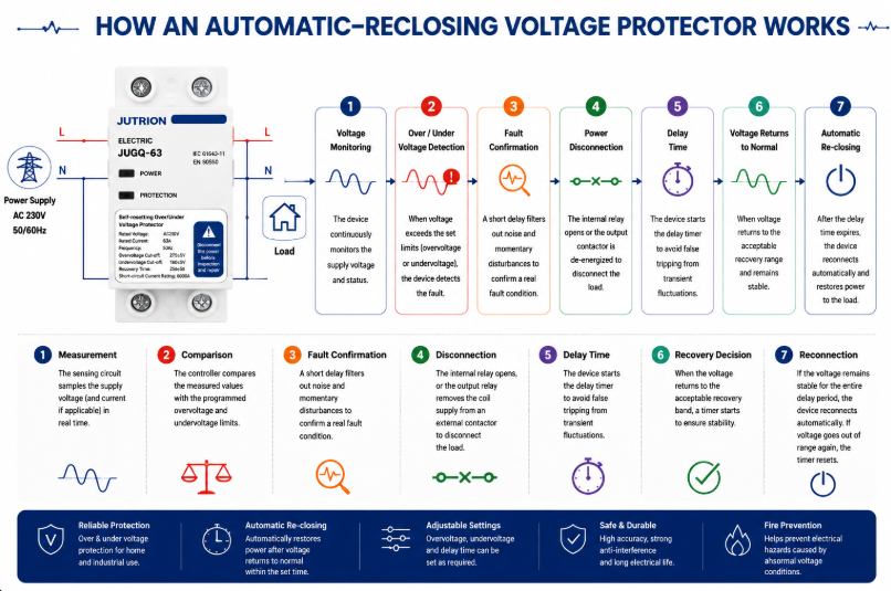
자동 재폐로 전압 보호기 작동 원리 다이어그램- 측정: 감지 회로는 공급 전압을 샘플링하고, 적용 가능한 모델에서는 전류 또는 추가 위상 조건도 샘플링합니다.
- 비교: 컨트롤러는 측정된 값을 프로그래밍된 과전압 및 저전압 한계와 비교합니다.
- 고장 확인: 필터링 또는 트립 지연은 부하를 차단해서는 안 되는 사소한 노이즈와 매우 짧은 교란을 거부합니다.
- 차단: 내부 접점이 열리거나 출력 릴레이가 외부 접촉기의 코일 전원을 제거합니다.
- 지속적인 모니터링: 다운스트림 부하가 분리된 동안에도 전원은 계속 관찰됩니다.
- 복귀 결정: when voltage returns to the acceptable recovery band, a timer starts.
- Reconnection: if the source stays stable for the full delay, the device reconnects automatically. If voltage becomes unacceptable again, the timer resets.
Microprocessor-based digital sampling makes adjustable thresholds, time delays, displays and status logic practical in a compact DIN-rail device. Filtering is important in electrically noisy installations because nuisance trips can be nearly as disruptive as the voltage event itself. The filter and confirmation time should reject insignificant deviations without masking a sustained condition that can damage the load.
Why the Trip Level, Recovery Level, and Delay Must Work Together
A protector does not make one voltage decision. It normally makes at least three related decisions: when the supply has become unacceptable, when it has recovered far enough to be considered acceptable again, and how long it must remain stable before the load is reconnected. These values form one control strategy and should be reviewed together.
If the trip and recovery levels are too close, a supply hovering near the boundary can cause repeated opening and closing. A separate recovery value creates hysteresis: after an undervoltage trip, for example, voltage must rise to a healthier level before reconnection becomes possible. The reconnection timer then confirms that the recovery is stable rather than momentary.
The correct timing follows the load. A resistive heater may accept a relatively quick return. A refrigeration compressor may need a longer pause before restart. A panel with several motors may need staged reconnection so their combined inrush does not pull the supply below the threshold again. This is why an adjustable delay is an engineering parameter, not merely a convenience feature.
For an adjustable model, record the approved trip, recovery, and delay values as one setting set. Changing only the high or low threshold can alter the intended hysteresis and restart behavior. For a factory-calibrated model, confirm that the preset control window matches the destination supply and the connected equipment before standardizing it across a project.
How to Select an Over and Under Voltage Protector
1. Confirm the System Voltage, Frequency and Phase Arrangement
Start with the actual distribution system, not a catalogue headline. Record nominal phase-to-neutral and phase-to-phase voltage, frequency, single- or three-phase arrangement, number of conductors, neutral use and acceptable supply tolerance. IEC 60038 provides standard voltage references, including common 230/400 V low-voltage systems, but the project specification and local supply rules determine the final requirements.
For three-phase loads, determine whether the device must also supervise phase loss, phase sequence, imbalance and phase-to-neutral displacement. For a panel containing many single-phase loads, neutral-related monitoring may be more important than it is for a balanced three-wire motor load.
2. Define the Load That Will Be Disconnected
List the connected load, maximum demand, continuous current, inrush current and load type. A 40 A resistive circuit, a 40 A motor feeder and a 40 A bank of switched-mode power supplies do not impose identical switching duty. Identify compressors, pumps, transformers, capacitive inputs and equipment with internal undervoltage or restart controls.
Do not select solely from the service breaker rating. The protector must be suitable for the current it carries and the switching duty it performs, while the upstream protective device must provide the required short-circuit protection. Terminal capacity, conductor size, ambient temperature and enclosure ventilation also matter.
3. Decide Between Direct Switching and an External Contactor
A compact protector can switch a suitably rated load directly when its contact rating, utilization duty and prospective fault coordination are appropriate. For a larger panel, a motor-heavy load, frequent operation or a current beyond the protector’s direct-switching capability, use a monitoring relay or protector to control a correctly selected contactor. This separates the measurement logic from the power switching duty.
When an external contactor is used, check coil voltage, contactor utilization category, auxiliary contacts, control-circuit protection and fail-safe behavior. Decide what happens after a power loss and whether automatic restart is permitted by the process risk assessment.
4. Set the Overvoltage and Undervoltage Limits
The trip window should be wide enough to tolerate normal supply variation and narrow enough to protect the connected equipment. Use the most restrictive credible requirement from the equipment manufacturer, project specification and local installation rules. A value seen in a generic example is not automatically suitable for motors, refrigeration, medical equipment, telecom power supplies or process controls.
| Setting | Purpose | Selection question |
|---|---|---|
| Overvoltage trip level | Defines the high-voltage disconnection point | What sustained input can the most sensitive connected equipment tolerate? |
| Undervoltage trip level | Defines the low-voltage disconnection point | At what voltage can motors, contactors or power supplies no longer operate safely? |
| Trip delay | Rejects brief deviations | Which short disturbances can the load ride through without harm? |
| Recovery level | Defines when voltage is acceptable again | Is sufficient hysteresis provided to avoid repeated switching? |
| 재연결 지연 | Waits for stable supply and safe restart | Does the load need seconds or minutes before restart? |
5. Select Reconnection Delay for the Load
A short delay can restore lighting or non-critical resistive loads quickly. Refrigeration and air-conditioning compressors often require a longer delay to allow pressure equalization and avoid a hard restart. Multiple loads reconnecting simultaneously can create a new voltage dip, so large installations may require staged restarting rather than one common timer.
Automatic reconnection is convenient, but it is not appropriate everywhere. Machinery that could move unexpectedly may require manual reset, a safety controller or another supervised restart sequence. Voltage restoration must never bypass machine-safety requirements.
6. Check Poles, Neutral Arrangement and Isolation
Select the number of poles from the system earthing arrangement and installation requirements. Switching the neutral is not a universal rule. In some systems it is required; in others it may be prohibited or unnecessary. The choice must be coordinated with upstream bonding, source transfer arrangements and local codes. Never treat a two-pole or four-pole catalogue option as proof that it is correct for every network.
7. Verify Coordination and Installation Conditions
Confirm rated current, operational voltage, frequency, terminal capacity, mounting method, temperature range, enclosure protection and the required upstream protective device. Check short-circuit coordination rather than assuming a small modular device can interrupt any available fault current. Verify conductor torque and provide working space and ventilation according to the manufacturer’s instructions.
IEC 60364-4-44 addresses protection of low-voltage installations against voltage disturbances and electromagnetic disturbances. Apply the edition and national adoption required by the destination market; do not use an IEC reference as a substitute for a complete project design.
Standards and Export-Market Questions That Change the Specification
Standards references should define the engineering boundary, not decorate a product description. IEC 60364-4-44:2024 addresses protection of low-voltage installations against voltage disturbances and electromagnetic disturbances. It is an installation-level document: it helps designers consider the consequences of disturbances within an electrical installation, but it is not a model datasheet and does not by itself prove that a particular protector is suitable for a project.
IEC 60038 defines standard voltage values used as references for equipment and supply systems. Nominal voltage is the starting point for a protector setting, not the complete setting decision. Normal service variation, the connected equipment’s permissible input range, regional supply-quality requirements and the behavior of the recovery logic all affect the usable window.
Product Standard, Installation Code and Supply Quality
These three layers answer different questions. A product standard describes how a device is classified, constructed and tested. An installation code determines how equipment is selected and erected in a building or plant. A supply-quality document describes characteristics expected at the point of supply. A buyer should not substitute one layer for another. For example, knowing that a country uses a 230/400 V nominal system does not determine the required neutral switching, and an installation-code reference does not establish the short-circuit capability of an individual product.
The destination market may also use a national adoption of an IEC document with local modifications. North American projects use different system conventions, product listings and installation rules. The familiar functions—measure, compare, disconnect and delay reconnection—remain understandable, but product acceptance, conductor switching, enclosure marking and coordination have to be checked in the regional framework.
Certification Claims Must Match the Exact Model
Terms such as IEC, UL and CB should be supported by documentation that identifies the relevant standard, model or series, electrical ratings and issuing body. A general factory capability statement is not the same as a certificate covering every variant. Importers and panel builders should match the document reference to the ordered catalogue number and destination-market requirement.
The same discipline applies to rated current and protection claims. If a series includes several current or pole variants, evidence for one variant should not automatically be extended to all others. Where a protector includes overcurrent functionality, clarify its operating characteristic and its relationship to the upstream breaker. “Overcurrent” on a display does not automatically mean the device provides the short-circuit interruption performance expected from an MCB or MCCB.
A Compact Export Specification
Before comparing models, put the project conditions on one line: destination market; nominal voltage and frequency; phase and neutral arrangement; continuous current and load type; overvoltage and undervoltage limits; trip and reconnection timing; number of switched poles; direct switching or contactor control; upstream protection; mounting and environmental conditions; and required conformity documents. That line exposes mismatches quickly and prevents three products with the same front-panel current marking from being treated as equivalent.
For distributors serving several countries, adjustable models can reduce stock fragmentation, but only when setting control is managed. A setting range is useful if commissioning personnel know the approved values and unauthorized changes are prevented. For one stable market and a repeatable panel design, factory-calibrated thresholds may produce more consistent installation and simpler training. The export decision is therefore partly electrical and partly operational.
Choosing Between the Three JUTRION Series
JUTRION offers three over and under voltage protector series for different panel and procurement priorities. Product selection should still be confirmed against the required electrical ratings and project documentation.
| Selection point | JRGQ-63 | JQGQ-63 | JUGQ-63 |
|---|---|---|---|
| Series position | Flagship adjustable model | Compact digital model | Cost-effective preset model |
| Display and monitoring | Dual digital display with real-time voltage and current monitoring | Compact digital display with smart monitoring | Simplified interface for plug-and-play use |
| Voltage settings | Adjustable overvoltage and undervoltage parameters | Adjustable thresholds | Factory-calibrated thresholds |
| Additional function stated on the public page | Overcurrent protection and automatic reclosing | Automatic reclosing | Automatic reclosing |
| Installation format | 35 mm DIN-rail modular format | Space-saving DIN-rail format | Streamlined DIN-rail format |
| Best fit | Projects needing visible operating data and broad parameter control | High-density distribution boards where space matters | Standardized, high-volume applications requiring simple installation |
| Confirm from the ordered model datasheet | Rated voltage, current, poles, exact setting and delay ranges, terminals, temperature limits, dimensions, switching duty, upstream protection and model-specific conformity documents | ||
Choose JRGQ-63 when adjustment, current information and a more complete on-device interface are valuable. Choose JQGQ-63 when adjustable digital protection is needed but panel density is the main constraint. Choose JUGQ-63 when the required protection window matches the factory-calibrated configuration and consistency, simplicity and volume economics are more important than field adjustment.
A buyer should not compare only unit price. Normalize rated voltage, current, poles, adjustable range, trip and recovery logic, delay range, switching method, display, overcurrent function, terminals, certifications, packaging and customization. Two devices described as “63 A automatic voltage protectors” can offer materially different functions.
Apply the Selection Logic to Four Panel Scenarios
Commercial Distribution Board on an Unstable Grid
A small commercial facility experiences long evening brownouts and occasional high voltage during light-load periods. The panel supplies lighting, point-of-sale equipment, refrigeration and office electronics. A voltage protector can disconnect selected downstream circuits outside the approved window. Because refrigeration has a different restart requirement from lighting and office loads, the designer may divide the loads or use separate control so one common reconnection delay does not compromise either continuity or compressor protection.
OEM Panel for Pumps or HVAC Equipment
The load includes motors with high starting current and a control circuit sensitive to low voltage. Direct switching through a compact protector may not be the preferred architecture. The protector can monitor the source and command an AC contactor selected for the motor duty. The control design should prevent unsafe automatic restart and coordinate undervoltage behavior with the motor protection relay and process controller.
Three-Phase Panel with Many Single-Phase Loads
A 400/230 V panel distributes different single-phase circuits across the three phases. Unequal loading makes an open neutral hazardous. The monitoring strategy should observe all relevant phase-to-neutral voltages and disconnect the affected distribution section if values diverge beyond permitted limits. Maintenance procedures must still locate and repair the neutral fault.
High-Volume Standardized Consumer Unit
An OEM produces many panels for one market with a stable, predefined protection specification. Field adjustment is not needed and could create commissioning inconsistency. A factory-calibrated automatic-reclosing model such as JUGQ-63 may provide a simpler fit, provided its nominal voltage, current, thresholds, poles and certification match the project.
Install, Commission, and Diagnose the Protection System
Installation and Commissioning Checklist
- Confirm the source is isolated and follow the project’s lockout procedure.
- Verify nominal voltage, frequency, phase arrangement and conductor identification.
- Confirm whether the protector switches the load directly or controls a contactor.
- Check upstream short-circuit and overload protection.
- Match conductor size and terminal capacity; tighten to the specified torque.
- Program thresholds and delays from the approved setting schedule.
- Test overvoltage and undervoltage operation with suitable test equipment rather than by creating unsafe supply conditions.
- Verify the trip indication, contact state and reconnection timer.
- Confirm that motors and machinery restart safely.
- Record settings, model, serial or batch information and commissioning results.
After commissioning, investigate frequent trips instead of simply widening thresholds. Repeated operation may reveal a loose neutral, undersized feeder, overloaded transformer, generator-control issue or supply-quality problem. The protector is often the messenger, not the cause.
Common Selection and Installation Mistakes
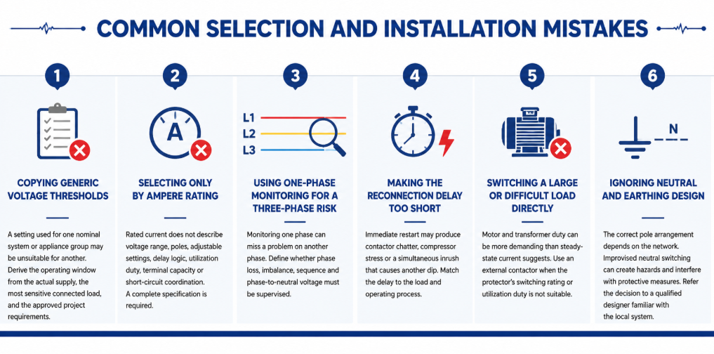
Common selection and installation mistakes of automatic re-closing voltage protector- Copying generic voltage thresholds: A setting used for one nominal system or appliance group may be unsuitable for another. Derive the operating window from the actual supply, the most sensitive connected load, and the approved project requirements.
- Selecting only by ampere rating: Rated current does not describe voltage range, poles, adjustable settings, delay logic, utilization duty, terminal capacity or short-circuit coordination. A complete specification is required.
- Using one-phase monitoring for a three-phase risk: Monitoring one phase can miss a problem on another phase. Define whether phase loss, imbalance, sequence and phase-to-neutral voltage must be supervised.
- Making the reconnection delay too short: Immediate restart may produce contactor chatter, compressor stress or a simultaneous inrush that causes another dip. Match the delay to the load and operating process.
- Switching a large or difficult load directly: Motor and transformer duty can be more demanding than steady-state current suggests. Use an external contactor when the protector’s switching rating or utilization duty is not suitable.
- Ignoring neutral and earthing design: The correct pole arrangement depends on the network. Improvised neutral switching can create hazards and interfere with protective measures. Refer the decision to a qualified designer familiar with the local system.
Maintenance and Troubleshooting in Service
A voltage protector normally requires little routine intervention, but it should still be included in the panel inspection plan. Check for discoloration, heat damage, loose terminals, dust accumulation, cracked housings and abnormal display values. Compare the displayed voltage with a calibrated instrument when readings appear doubtful. Thermal imaging under representative load can help reveal a poor terminal connection, although it does not replace torque checks performed under safe isolated conditions.
Keep a record of trip events where operational continuity matters. The time, displayed voltage, affected phase, connected load and recovery time can distinguish a supply-quality issue from a load-related voltage drop. Several trips at the same production time may indicate feeder demand. Random high and low readings across single-phase circuits may point toward a neutral problem. Trips only during generator operation may indicate AVR settings, frequency variation or poor generator/load matching.
| Observed symptom | Possible causes to investigate | Useful checks |
|---|---|---|
| Trips immediately after installation | Wrong nominal-voltage model, wiring error, threshold set too close to normal supply | Verify model, line/neutral connections, measured voltage and setting schedule |
| Repeated trip and reconnect cycle | Insufficient hysteresis, unstable supply, restart inrush causing another dip | Record voltage during restart; review recovery level and delay |
| Display is on but load remains off | Active fault, delay still counting, damaged contact, external contactor/control issue | Read status indication and test control circuit according to the manual |
| One phase shows abnormal voltage | Loose phase or neutral, phase imbalance, upstream connection fault | Isolate safely and inspect all conductors; measure every relevant phase |
| Terminal temperature is high | Loose termination, unsuitable conductor, overload, poor enclosure ventilation | Measure load current, inspect conductor preparation and verify specified torque |
Do not repeatedly reset or bypass a protector until the cause is known. Bypassing removes the protection at the moment the system may be demonstrating a genuine fault. If the device has switched a severe or repeated load, inspect its contacts and connected conductors according to the manufacturer’s service instructions. Replace a unit that shows heat damage, unreliable switching or readings outside its declared accuracy rather than attempting an unapproved repair.
Settings should also be controlled. For adjustable models, record the approved values during commissioning and restrict unauthorized changes. If equipment is added, the supply changes, or the panel is exported to a market with a different nominal voltage, review the entire setting schedule. A protector that was correctly configured for the original installation may be inappropriate after a system modification.
자주 묻는 질문
보호기가 부하를 다시 연결하기 전에 기다리는 이유는 무엇입니까?
지연은 전압이 회복되었음을 확인하고 빠른 재투입을 방지합니다. 또한 압축기의 재시동 시간을 제공하고 동시 돌입 전류로 인해 전원이 다시 낮아질 가능성을 줄일 수 있습니다.
중성선 손실을 방지할 수 있습니까?
영향을 받은 상-중성선 전압을 감시하고 허용 범위를 벗어나면 차단함으로써 노출을 줄일 수 있습니다. 중성선 결함을 복구할 수는 없으며, 감시 장치는 모든 관련 상을 포함해야 합니다.
과전압/저전압 보호기가 전압 안정기와 같은 것인가요?
아니요. 보호기는 부하를 차단합니다. 안정기 또는 AVR은 출력 전압을 계속 공급하면서 보정하려고 시도합니다. 차단이 필요한지 연속적인 조정 전원이 필요한지에 따라 선택하십시오.
암페어 정격은 어떻게 선택하나요?
장치가 전달할 최대 전류를 결정하고, 부하 듀티와 돌입 전류를 고려하여 필요한 단자와 설치 조건에 맞는 적절한 정격을 선택하고, 상류 측 고장 보호와 협조시키십시오. 직접 스위칭이 적합하지 않은 경우에는 외부 접촉기를 사용하십시오.
재연결 지연 시간은 얼마를 사용해야 하나요?
Use the connected equipment manufacturer’s requirement and the process risk assessment. General lighting may accept a short delay; compressors and staged systems may need substantially longer or sequenced reconnection.
보호기가 왜 계속 작동하나요?
가능한 원인으로는 실제 공급 변동, 느슨한 중성선, 과부하된 피더, 발전기 조정 문제, 잘못된 설정, 배선 오류 또는 장치/부하 불일치가 있습니다. 임계값을 넓히기 전에 시스템을 측정하고 진단하십시오.
Choose the Protection Boundary Before the Product Variant
An over and under voltage protector is most effective when its operating window is defined precisely. Selection becomes a practical sequence: establish the nominal system and monitored conductors, understand the load, choose direct switching or contactor control, set coordinated trip and recovery values, choose a safe reconnection delay, verify poles and neutral design, and test the completed panel under controlled conditions.
For a model recommendation, send JUTRION the nominal voltage and frequency, phase and neutral arrangement, load current and type, required thresholds and delay, pole configuration, upstream protective device, installation conditions, certification market and order quantity. The JRGQ-63, JQGQ-63 and JUGQ-63 ranges can then be compared against the actual project instead of selected from current rating alone.
