

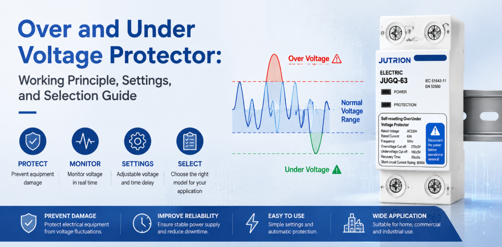
Zasada działania i poradnik doboru ochronnika nadnapięciowego i podnapięciowegoSzybka odpowiedź: Co robi ochronnik nadnapięciowy i podnapięciowy?
Ochronnik nadnapięciowy i podnapięciowy odłącza obwód, gdy napięcie zasilania pozostaje powyżej lub poniżej wybranych limitów, a następnie ponownie załącza po powrocie napięcia i upływie ustawionego opóźnienia. Chroni przed trwałym przepięciem, podnapięciem i zanikami napięcia. Nie zastępuje SPD dla przepięć przejściowych, wyłącznika nadprądowego dla przetężeń, RCD dla prądu upływowego ani AVR, gdy wymagana jest ciągła korekcja napięcia.
“Ochrona napięciowa” jest często traktowana jako jeden temat, ale rozdzielnica może być narażona na kilka zasadniczo różnych zdarzeń. Przepięcie wywołane piorunem może trwać mikrosekundy. Problem z regulacją w sieci energetycznej lub nieprawidłowo podłączony transformator może utrzymywać napięcie zasilania powyżej normalnego zakresu przez wiele minut. Przeciążony zasilacz może powodować długotrwały zanik napięcia. Poluzowany lub przerwany przewód neutralny może w układzie trójfazowym czteroprzewodowym podnieść napięcie niektórych odbiorników jednofazowych znacznie powyżej wartości znamionowej, jednocześnie obniżając napięcie innych.
Żadne pojedyncze urządzenie nie obsłuży wszystkich tych warunków. Ogranicznik przepięć ogranicza krótkie, wysokoenergetyczne przepięcia przejściowe. Ochronnik nadnapięciowy i podnapięciowy odłącza obciążenie, gdy napięcie skuteczne zasilania pozostaje poza dopuszczalnymi limitami. Wyłącznik przerywa prąd przeciążeniowy i zwarciowy. RCD lub RCBO reaguje na prąd różnicowy. Pierwszą zasadą doboru nie jest więc prąd znamionowy ani typ wyświetlacza: jest nią dopasowanie urządzenia do zakłócenia.
Dla producenta rozdzielnic lub dystrybutora użytecznym pytaniem nie jest więc to, czy “ochrona napięciowa” jest obecna. Użytecznym pytaniem jest to, czy każde zakłócenie ma zdefiniowaną metodę wykrywania, reakcję przełączania i zasadę powrotu.
Granica ochrony: Dopasuj każdy problem napięciowy do właściwego urządzenia
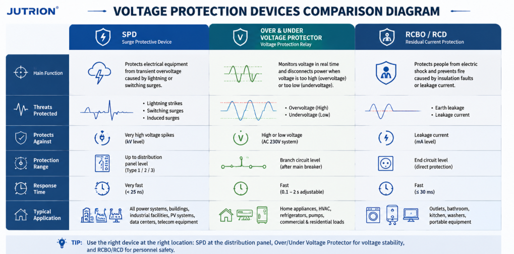
Schemat porównawczy urządzeń ochrony napięciowej pokazujący funkcje SPD, ochronnika nadnapięciowego i podnapięciowego oraz RCBO RCD| Zakłócenie | Typowy czas trwania | Reakcja podstawowa | Urządzenie normalnie odpowiedzialne |
|---|---|---|---|
| Przepięcie piorunowe lub łączeniowe | Mikrosekundy do milisekund | Ograniczenie i odprowadzenie energii przepięcia | Ogranicznik przepięć (SPD) |
| Trwałe przepięcie | Sekundy, minuty lub dłużej | Odłączenie zagrożonego obciążenia | Ochronnik nadnapięciowy lub przekaźnik kontroli napięcia |
| Podnapięcie lub zanik napięcia | Sekundy, minuty lub dłużej | Odłączenie zanim sprzęt się przegrzeje, zatrzyma lub zacznie działać nieprawidłowo | Ochronnik podnapięciowy lub przekaźnik kontroli napięcia |
| Przeciążenie lub zwarcie | Zależy od wielkości prądu zwarciowego | Przerwanie nadmiernego prądu | MCB lub MCCB |
| Prąd upływowy | Milisekundy do trwałego | Wykrycie prądu różnicowego i odłączenie | RCCB lub RCBO |
| Wahania napięcia wymagające ciągłej korekcji | Ciągłe lub powtarzające się | Podbicie, obniżenie lub stabilizacja napięcia | Stabilizator napięcia lub AVR |
Dobrze zaprojektowana rozdzielnica może zawierać kilka z tych urządzeń, ponieważ działają one w różnych skalach czasowych i obserwują różne wielkości elektryczne. Zainstalowanie SPD nie sprawia, że ochrona przed trwałym przepięciem staje się zbędna. Dodanie ochronnika napięciowego nie zwiększa zdolności wyłączania małego wyłącznika nadprądowego. Prawidłowa koordynacja jest addytywna, a nie konkurencyjna.
Dlaczego wyłącznik nadprądowy może nie zadziałać przy złym napięciu
Konwencjonalny wyłącznik nadprądowy reaguje głównie na prąd. Jeśli napięcie zasilania wzrośnie, ale podłączone urządzenia nie pobiorą od razu wystarczającego prądu, aby przekroczyć charakterystykę czasowo-prądową wyłącznika, wyłącznik może pozostać zamknięty, podczas gdy wrażliwa elektronika będzie narażona na szkodliwe naprężenia elektryczne. Podczas zaniżonego napięcia silnik może pobierać większy prąd, aby wytworzyć wymagany moment obrotowy, ale dokładna reakcja zależy od silnika, obciążenia i sterownika. Wyłącznik może w końcu zadziałać, jednak nie został zaprojektowany do nadzorowania, czy napięcie zasilania jest dopuszczalne.
Zabezpieczenie nadnapięciowe i podnapięciowe zamyka ten martwy punkt, mierząc napięcie bezpośrednio. Jeśli w zabezpieczeniu zintegrowano również ochronę nadprądową, funkcja ta powinna być nadal skoordynowana z poprzedzającym urządzeniem zabezpieczającym przed zwarciem. Poprzedzający MCB lub MCCB pozostaje niezbędny do bezpiecznego przerwania zwarcia.
Gdzie pasuje zabezpieczenie nadnapięciowe i podnapięciowe
Zabezpieczenie nadnapięciowe i podnapięciowe to urządzenie monitorująco-łączeniowe stosowane między źródłem zasilania a odbiornikiem lub obwodem rozdzielczym po stronie wtórnej. Jego obwód pomiarowy próbkuje napięcie wejściowe. Sterownik porównuje zmierzoną wartość ze skonfigurowanymi górnymi i dolnymi progami. Jeśli napięcie pozostaje poza dozwolonym oknem przez obowiązujący czas zadziałania, urządzenie otwiera swoje styki łączeniowe lub nakazuje zewnętrznemu stycznikowi otwarcie.
Modele z automatycznym ponownym załączaniem nadal monitorują źródło, gdy odbiornik jest odłączony. Gdy napięcie powróci w granice regeneracji, sterownik rozpoczyna opóźnienie ponownego załączenia. Odbiornik zostaje przywrócony tylko wtedy, gdy zasilanie pozostaje dopuszczalne przez cały czas opóźnienia. Zapobiega to szybkiemu cyklicznemu załączaniu i wyłączaniu oraz daje sprężarkom, systemom chłodniczym, elektronicznym zasilaczom i innym urządzeniom czas na ustabilizowanie się przed ponownym uruchomieniem.
Typowe nazwy obejmują zabezpieczenie nadnapięciowe/podnapięciowe, urządzenie ochrony napięciowej, automatyczny przełącznik napięcia, samoresetujące zabezpieczenie napięciowe, zabezpieczenie z automatycznym ponownym załączaniem oraz przekaźnik kontroli napięcia. Terminy te nakładają się, ale nie zawsze opisują identyczne produkty. Niektóre jednostki przełączają odbiornik bezpośrednio. Inne zapewniają styki przekaźnikowe dla zewnętrznego Stycznik AC. Niektóre monitorują tylko napięcie; inne dodają pomiar prądu, ochronę nadprądową, kontrolę zaniku fazy lub wyświetlacz cyfrowy.
Co długotrwałe przepięcie i zaniżone napięcie robią ze sprzętem
Długotrwałe przepięcie
Długotrwałe przepięcie zwiększa naprężenia dielektryczne i może przyspieszać starzenie izolacji. Kondensatory zasilaczy, warystory, sterowniki LED, transformatory sterownicze i wejścia półprzewodnikowe mogą pracować bliżej lub poza swoimi granicami projektowymi. Moc grzewcza rezystancyjna rośnie w przybliżeniu z kwadratem napięcia, gdy rezystancja jest stała, więc nawet umiarkowany wzrost napięcia może wywołać większy wzrost ciepła. Skutkiem może być natychmiastowa awaria, uciążliwe wyłączenie lub skrócona żywotność, którą trudno powiązać z pierwotnym zdarzeniem zasilania.
Możliwe przyczyny obejmują nieprawidłowe odczepy transformatora, usterki regulatora, błędy okablowania, problemy z AVR generatora, zrzut obciążenia, zwarcia w przewodzie neutralnym oraz zasilanie nieodpowiednie dla podłączonych urządzeń. Zabezpieczenie napięciowe nie może usunąć przyczyny, ale może odizolować odbiornik, dopóki stan ten występuje.
Zaniżone napięcie i spadki napięcia
Podnapięcie to nie tylko “mniejsza moc”. Silniki mogą nie osiągać prędkości lub mogą utknąć pod obciążeniem. Styczniki mogą brzęczeć lub odpadać. Przekaźniki i sterowniki mogą resetować się w nieprzewidywalny sposób. Obciążenia elektroniczne o stałej mocy mogą próbować pobierać większy prąd w miarę spadku napięcia, zwiększając naprężenia cieplne przewodów i podzespołów. Sprężarki chłodnicze są szczególnie wrażliwe na wielokrotne ponowne uruchomienia, zanim ciśnienia się wyrównają.
Prawidłowa reakcja zależy od obciążenia. Niektóre urządzenia elektroniczne mają szeroki zakres napięcia wejściowego i mogą przetrwać umiarkowany spadek napięcia. Pompa napędzana silnikiem może wymagać szybkiego odłączenia. Krytyczny system sterowania może wymagać zasilacza UPS, a nie prostego odłączenia. Próg i opóźnienie zabezpieczenia muszą zatem być dobrane na podstawie wymagań urządzenia, a nie ślepo skopiowane z innej rozdzielnicy.
Utracony przewód neutralny: Krytyczne zagrożenie w trójfazowym układzie czteroprzewodowym
W zrównoważonym trójfazowym układzie czteroprzewodowym obciążenia fazowo-neutralne są podobne, a prąd w przewodzie neutralnym może być stosunkowo niski. Rzeczywiste instalacje rzadko są idealnie zrównoważone. Jeśli przewód neutralny poluzuje się lub przerwie powyżej niezrównoważonych obciążeń jednofazowych, punkt neutralny może się przesunąć. Napięcia fazowo-neutralne są wtedy określane przez impedancje obciążeń, zamiast pozostawać stałe na wartościach nominalnych.
Jedna grupa obciążeń może otrzymać poważne przepięcie, podczas gdy inna otrzyma zbyt niskie napięcie, nawet jeśli napięcie międzyfazowe nadal wydaje się normalne. To sprawia, że zdarzenie przerwy w przewodzie neutralnym jest szczególnie niebezpieczne w mieszanych rozdzielnicach komercyjnych, mieszkalnych, telekomunikacyjnych i lekkiego przemysłu. Uszkodzenie sprzętu może nastąpić, zanim zwykłe zabezpieczenie nadprądowe wykryje wystarczająco duże zwarcie, aby zadziałać.
Trójfazowy układ monitorowania napięcia powinien oceniać każdą istotną fazę oraz, jeśli wymaga tego aplikacja, napięcia fazowo-neutralne. Utrata fazy, niezrównoważenie faz i integralność przewodu neutralnego powinny być rozpatrywane wprost. Pojedynczy pomiar na jednej fazie nie zastępuje pełnego nadzoru trójfazowego obciążenia czteroprzewodowego.
Uwaga projektowa: zabezpieczenie napięciowe zmniejsza narażenie urządzenia; nie czyni wadliwego przewodu neutralnego bezpiecznym. Poluzowane połączenia, przewody o zbyt małym przekroju, korozja i awarie sieci zasilającej powyżej muszą być wykryte i usunięte.
Zabezpieczenie jednofazowe i trójfazowe to różne decyzje projektowe
Zabezpieczenie jednofazowe zwykle podejmuje jedną centralną decyzję: czy zmierzone napięcie fazowo-neutralne mieści się w zatwierdzonym zakresie roboczym? To brzmi prosto, ale instalacja nadal musi określić napięcie nominalne, prąd przewodzony przez urządzenie, czy jeden czy dwa przewody mają być przełączane oraz jak traktowany jest przewód neutralny w lokalnym systemie uziemienia. Produkt oznaczony dla obwodu o napięciu nominalnym 230 V nie może być wybrany wyłącznie na podstawie oznaczenia prądu 63 A.
Zastosowania jednofazowe obejmują zwykle mieszkania, małe sklepy, szafy telekomunikacyjne, obwody chłodnicze, rozdzielnice oświetleniowe i pojedyncze maszyny. Ich obciążenia mogą reagować bardzo różnie na to samo zdarzenie. Sterownik LED może tolerować krótki spadek napięcia, który powoduje zwolnienie cewki stycznika. Lodówka może przetrwać spadek, ale zostać uszkodzona przez natychmiastowy restart. Dobrze dobrane zabezpieczenie łączy zatem prawidłowe okno napięciowe z opóźnieniem powrotu, które odpowiada najbardziej wrażliwemu na restart obciążeniu poniżej.
Co może wymagać obserwacji trójfazowe zabezpieczenie
Zabezpieczenie trójfazowe to nie tylko trzy kopie pomiaru jednofazowego. Funkcja monitorowania może wymagać oceny napięcia międzyfazowego, napięcia fazowo-neutralnego, utraty fazy, kolejności faz i niezrównoważenia napięcia. Które funkcje mają znaczenie, zależy od obciążenia i układu przewodów. Trójprzewodowy obwód zasilający silnik ma inny profil ryzyka niż czteroprzewodowa rozdzielnica zasilająca kilkadziesiąt nierównych obwodów jednofazowych.
- Utrata fazy oznacza, że jedna faza zasilania jest nieobecna lub zanikła. Pracujący silnik trójfazowy może kontynuować pracę z nadmiernym prądem w pozostałych fazach, zmniejszonym momentem obrotowym i szybkim nagrzewaniem. Zabezpieczenie przeznaczone do pracy z silnikiem powinno wykrywać ten stan lub współpracować z przekaźnikiem zabezpieczenia silnika, który to robi.
- Kolejność faz określa kierunek obrotów wielu silników trójfazowych. Zwykle ma znaczenie przy rozruchu lub po zmianach w okablowaniu zasilania. Funkcja nad- i podnapięciowa nie oznacza automatycznie zabezpieczenia kolejności faz, więc wymagana funkcja musi być wyraźnie określona.
- Niezrównoważenie napięcia opisuje nierówne napięcia fazowe. Pozornie umiarkowane niezrównoważenie napięcia może powodować znacznie większe niezrównoważenie prądu w silniku. Dopuszczalny limit powinien wynikać z projektu silnika i systemu. Urządzenie, które wyłącza tylko przy szerokich progach nad- i podnapięciowych, może nie zapewniać dedykowanego nadzoru niezrównoważenia.
- Przesunięcie punktu neutralnego jest kluczowe tam, gdzie obciążenia fazowo-neutralne są nierówne. Jeśli urządzenie trójfazowe mierzy tylko wartości międzyfazowe, może nie zauważyć szkodliwego podziału fazowo-neutralnego spowodowanego przerwą w przewodzie neutralnym. Producenci rozdzielnic powinni potwierdzić dokładnie, które napięcia wykrywa wybrane urządzenie, zamiast polegać na słowach “trójfazowy” w opisie.
| System i obciążenie | Pomiary do priorytetyzacji | Typowe podejście do przełączania |
|---|---|---|
| 230 V jednofazowa rozdzielnica końcowa | Nadnapięcie i podnapięcie fazowo-neutralne | Bezpośrednie przełączanie, gdy dopuszczają to parametry i koordynacja |
| 400 V trójfazowy obwód zasilający silnik | Napięcie międzyfazowe, utrata fazy, niezrównoważenie i ewentualnie kolejność faz | Urządzenie monitorujące sterujące stycznikiem przystosowanym do silnika |
| 400/230 V czteroprzewodowa rozdzielnica z obciążeniami mieszanymi | Wszystkie istotne napięcia fazowo-neutralne, utrata fazy i przesunięcie związane z przewodem neutralnym | Wielobiegunowe odłączanie dobrane do układu uziemienia |
| Rozdzielnica zasilana z generatora | Napięcie na aktywnym źródle plus częstotliwość i status systemu przełączania, jeśli wymagane | Koordynacja ze sterownikiem generatora i urządzeniami przełączającymi |
To rozróżnienie wpływa również na porównanie produktów. Kompaktowe jednofazowe zabezpieczenie z samoczynnym ponownym załączaniem może być doskonałym urządzeniem do rozdzielnicy mieszkaniowej, ale niewłaściwą architekturą sterowania dla dużej trójfazowej rozdzielnicy silnikowej. Z drugiej strony złożony przekaźnik monitorowania faz i zestaw styczników może dodawać koszty i miejsce w rozdzielnicy, których znormalizowany obwód jednofazowy nie potrzebuje. Właściwy wybór to najmniejsza architektura, która nadzoruje każdy stan napięcia mogący uszkodzić rzeczywiste obciążenie.
Jak działa zabezpieczenie napięciowe z automatycznym ponownym załączaniem
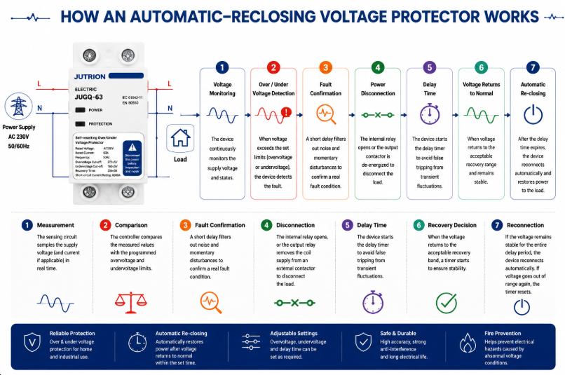
Schemat działania zabezpieczenia napięciowego z automatycznym ponownym załączaniem- Pomiar: obwód pomiarowy próbkuje napięcie zasilania oraz, w odpowiednich modelach, prąd lub dodatkowe warunki fazowe.
- Porównanie: sterownik porównuje zmierzone wartości z zaprogramowanymi limitami przepięcia i niedopięcia.
- Potwierdzenie usterki: filtrowanie lub opóźnienie wyzwalania odrzuca nieistotne zakłócenia i bardzo krótkie zaburzenia, które nie powinny odłączać obciążenia.
- Odłączenie: styki wewnętrzne rozwierają się lub przekaźnik wyjściowy usuwa zasilanie cewki z zewnętrznego stycznika.
- Ciągłe monitorowanie: źródło pozostaje pod obserwacją, podczas gdy obciążenie po stronie odbioru jest odizolowane.
- Decyzja o powrocie: gdy napięcie powróci do akceptowalnego pasma powrotu, uruchamiany jest licznik czasu.
- Reconnection: if the source stays stable for the full delay, the device reconnects automatically. If voltage becomes unacceptable again, the timer resets.
Microprocessor-based digital sampling makes adjustable thresholds, time delays, displays and status logic practical in a compact DIN-rail device. Filtering is important in electrically noisy installations because nuisance trips can be nearly as disruptive as the voltage event itself. The filter and confirmation time should reject insignificant deviations without masking a sustained condition that can damage the load.
Why the Trip Level, Recovery Level, and Delay Must Work Together
A protector does not make one voltage decision. It normally makes at least three related decisions: when the supply has become unacceptable, when it has recovered far enough to be considered acceptable again, and how long it must remain stable before the load is reconnected. These values form one control strategy and should be reviewed together.
If the trip and recovery levels are too close, a supply hovering near the boundary can cause repeated opening and closing. A separate recovery value creates hysteresis: after an undervoltage trip, for example, voltage must rise to a healthier level before reconnection becomes possible. The reconnection timer then confirms that the recovery is stable rather than momentary.
The correct timing follows the load. A resistive heater may accept a relatively quick return. A refrigeration compressor may need a longer pause before restart. A panel with several motors may need staged reconnection so their combined inrush does not pull the supply below the threshold again. This is why an adjustable delay is an engineering parameter, not merely a convenience feature.
For an adjustable model, record the approved trip, recovery, and delay values as one setting set. Changing only the high or low threshold can alter the intended hysteresis and restart behavior. For a factory-calibrated model, confirm that the preset control window matches the destination supply and the connected equipment before standardizing it across a project.
How to Select an Over and Under Voltage Protector
1. Confirm the System Voltage, Frequency and Phase Arrangement
Start with the actual distribution system, not a catalogue headline. Record nominal phase-to-neutral and phase-to-phase voltage, frequency, single- or three-phase arrangement, number of conductors, neutral use and acceptable supply tolerance. IEC 60038 provides standard voltage references, including common 230/400 V low-voltage systems, but the project specification and local supply rules determine the final requirements.
For three-phase loads, determine whether the device must also supervise phase loss, phase sequence, imbalance and phase-to-neutral displacement. For a panel containing many single-phase loads, neutral-related monitoring may be more important than it is for a balanced three-wire motor load.
2. Define the Load That Will Be Disconnected
List the connected load, maximum demand, continuous current, inrush current and load type. A 40 A resistive circuit, a 40 A motor feeder and a 40 A bank of switched-mode power supplies do not impose identical switching duty. Identify compressors, pumps, transformers, capacitive inputs and equipment with internal undervoltage or restart controls.
Do not select solely from the service breaker rating. The protector must be suitable for the current it carries and the switching duty it performs, while the upstream protective device must provide the required short-circuit protection. Terminal capacity, conductor size, ambient temperature and enclosure ventilation also matter.
3. Decide Between Direct Switching and an External Contactor
A compact protector can switch a suitably rated load directly when its contact rating, utilization duty and prospective fault coordination are appropriate. For a larger panel, a motor-heavy load, frequent operation or a current beyond the protector’s direct-switching capability, use a monitoring relay or protector to control a correctly selected contactor. This separates the measurement logic from the power switching duty.
When an external contactor is used, check coil voltage, contactor utilization category, auxiliary contacts, control-circuit protection and fail-safe behavior. Decide what happens after a power loss and whether automatic restart is permitted by the process risk assessment.
4. Set the Overvoltage and Undervoltage Limits
The trip window should be wide enough to tolerate normal supply variation and narrow enough to protect the connected equipment. Use the most restrictive credible requirement from the equipment manufacturer, project specification and local installation rules. A value seen in a generic example is not automatically suitable for motors, refrigeration, medical equipment, telecom power supplies or process controls.
| Setting | Purpose | Selection question |
|---|---|---|
| Overvoltage trip level | Defines the high-voltage disconnection point | What sustained input can the most sensitive connected equipment tolerate? |
| Undervoltage trip level | Defines the low-voltage disconnection point | At what voltage can motors, contactors or power supplies no longer operate safely? |
| Trip delay | Rejects brief deviations | Which short disturbances can the load ride through without harm? |
| Recovery level | Defines when voltage is acceptable again | Is sufficient hysteresis provided to avoid repeated switching? |
| Reconnection delay | Waits for stable supply and safe restart | Does the load need seconds or minutes before restart? |
5. Select Reconnection Delay for the Load
A short delay can restore lighting or non-critical resistive loads quickly. Refrigeration and air-conditioning compressors often require a longer delay to allow pressure equalization and avoid a hard restart. Multiple loads reconnecting simultaneously can create a new voltage dip, so large installations may require staged restarting rather than one common timer.
Automatic reconnection is convenient, but it is not appropriate everywhere. Machinery that could move unexpectedly may require manual reset, a safety controller or another supervised restart sequence. Voltage restoration must never bypass machine-safety requirements.
6. Check Poles, Neutral Arrangement and Isolation
Select the number of poles from the system earthing arrangement and installation requirements. Switching the neutral is not a universal rule. In some systems it is required; in others it may be prohibited or unnecessary. The choice must be coordinated with upstream bonding, source transfer arrangements and local codes. Never treat a two-pole or four-pole catalogue option as proof that it is correct for every network.
7. Verify Coordination and Installation Conditions
Confirm rated current, operational voltage, frequency, terminal capacity, mounting method, temperature range, enclosure protection and the required upstream protective device. Check short-circuit coordination rather than assuming a small modular device can interrupt any available fault current. Verify conductor torque and provide working space and ventilation according to the manufacturer’s instructions.
IEC 60364-4-44 addresses protection of low-voltage installations against voltage disturbances and electromagnetic disturbances. Apply the edition and national adoption required by the destination market; do not use an IEC reference as a substitute for a complete project design.
Standards and Export-Market Questions That Change the Specification
Standards references should define the engineering boundary, not decorate a product description. IEC 60364-4-44:2024 addresses protection of low-voltage installations against voltage disturbances and electromagnetic disturbances. It is an installation-level document: it helps designers consider the consequences of disturbances within an electrical installation, but it is not a model datasheet and does not by itself prove that a particular protector is suitable for a project.
IEC 60038 defines standard voltage values used as references for equipment and supply systems. Nominal voltage is the starting point for a protector setting, not the complete setting decision. Normal service variation, the connected equipment’s permissible input range, regional supply-quality requirements and the behavior of the recovery logic all affect the usable window.
Product Standard, Installation Code and Supply Quality
These three layers answer different questions. A product standard describes how a device is classified, constructed and tested. An installation code determines how equipment is selected and erected in a building or plant. A supply-quality document describes characteristics expected at the point of supply. A buyer should not substitute one layer for another. For example, knowing that a country uses a 230/400 V nominal system does not determine the required neutral switching, and an installation-code reference does not establish the short-circuit capability of an individual product.
The destination market may also use a national adoption of an IEC document with local modifications. North American projects use different system conventions, product listings and installation rules. The familiar functions—measure, compare, disconnect and delay reconnection—remain understandable, but product acceptance, conductor switching, enclosure marking and coordination have to be checked in the regional framework.
Certification Claims Must Match the Exact Model
Terms such as IEC, UL and CB should be supported by documentation that identifies the relevant standard, model or series, electrical ratings and issuing body. A general factory capability statement is not the same as a certificate covering every variant. Importers and panel builders should match the document reference to the ordered catalogue number and destination-market requirement.
The same discipline applies to rated current and protection claims. If a series includes several current or pole variants, evidence for one variant should not automatically be extended to all others. Where a protector includes overcurrent functionality, clarify its operating characteristic and its relationship to the upstream breaker. “Overcurrent” on a display does not automatically mean the device provides the short-circuit interruption performance expected from an MCB or MCCB.
A Compact Export Specification
Before comparing models, put the project conditions on one line: destination market; nominal voltage and frequency; phase and neutral arrangement; continuous current and load type; overvoltage and undervoltage limits; trip and reconnection timing; number of switched poles; direct switching or contactor control; upstream protection; mounting and environmental conditions; and required conformity documents. That line exposes mismatches quickly and prevents three products with the same front-panel current marking from being treated as equivalent.
For distributors serving several countries, adjustable models can reduce stock fragmentation, but only when setting control is managed. A setting range is useful if commissioning personnel know the approved values and unauthorized changes are prevented. For one stable market and a repeatable panel design, factory-calibrated thresholds may produce more consistent installation and simpler training. The export decision is therefore partly electrical and partly operational.
Choosing Between the Three JUTRION Series
JUTRION offers three zabezpieczenie nad- i podnapięciowe series for different panel and procurement priorities. Product selection should still be confirmed against the required electrical ratings and project documentation.
| Selection point | JRGQ-63 | JQGQ-63 | JUGQ-63 |
|---|---|---|---|
| Series position | Flagship adjustable model | Compact digital model | Cost-effective preset model |
| Display and monitoring | Dual digital display with real-time voltage and current monitoring | Compact digital display with smart monitoring | Simplified interface for plug-and-play use |
| Voltage settings | Adjustable overvoltage and undervoltage parameters | Adjustable thresholds | Factory-calibrated thresholds |
| Additional function stated on the public page | Overcurrent protection and automatic reclosing | Automatic reclosing | Automatic reclosing |
| Format instalacji | 35 mm DIN-rail modular format | Space-saving DIN-rail format | Streamlined DIN-rail format |
| Best fit | Projects needing visible operating data and broad parameter control | High-density distribution boards where space matters | Standardized, high-volume applications requiring simple installation |
| Confirm from the ordered model datasheet | Rated voltage, current, poles, exact setting and delay ranges, terminals, temperature limits, dimensions, switching duty, upstream protection and model-specific conformity documents | ||
Choose JRGQ-63 when adjustment, current information and a more complete on-device interface are valuable. Choose JQGQ-63 when adjustable digital protection is needed but panel density is the main constraint. Choose JUGQ-63 when the required protection window matches the factory-calibrated configuration and consistency, simplicity and volume economics are more important than field adjustment.
A buyer should not compare only unit price. Normalize rated voltage, current, poles, adjustable range, trip and recovery logic, delay range, switching method, display, overcurrent function, terminals, certifications, packaging and customization. Two devices described as “63 A automatic voltage protectors” can offer materially different functions.
Apply the Selection Logic to Four Panel Scenarios
Commercial Distribution Board on an Unstable Grid
A small commercial facility experiences long evening brownouts and occasional high voltage during light-load periods. The panel supplies lighting, point-of-sale equipment, refrigeration and office electronics. A voltage protector can disconnect selected downstream circuits outside the approved window. Because refrigeration has a different restart requirement from lighting and office loads, the designer may divide the loads or use separate control so one common reconnection delay does not compromise either continuity or compressor protection.
OEM Panel for Pumps or HVAC Equipment
The load includes motors with high starting current and a control circuit sensitive to low voltage. Direct switching through a compact protector may not be the preferred architecture. The protector can monitor the source and command an AC contactor selected for the motor duty. The control design should prevent unsafe automatic restart and coordinate undervoltage behavior with the motor protection relay and process controller.
Three-Phase Panel with Many Single-Phase Loads
A 400/230 V panel distributes different single-phase circuits across the three phases. Unequal loading makes an open neutral hazardous. The monitoring strategy should observe all relevant phase-to-neutral voltages and disconnect the affected distribution section if values diverge beyond permitted limits. Maintenance procedures must still locate and repair the neutral fault.
High-Volume Standardized Consumer Unit
An OEM produces many panels for one market with a stable, predefined protection specification. Field adjustment is not needed and could create commissioning inconsistency. A factory-calibrated automatic-reclosing model such as JUGQ-63 may provide a simpler fit, provided its nominal voltage, current, thresholds, poles and certification match the project.
Install, Commission, and Diagnose the Protection System
Installation and Commissioning Checklist
- Confirm the source is isolated and follow the project’s lockout procedure.
- Verify nominal voltage, frequency, phase arrangement and conductor identification.
- Confirm whether the protector switches the load directly or controls a contactor.
- Check upstream short-circuit and overload protection.
- Match conductor size and terminal capacity; tighten to the specified torque.
- Program thresholds and delays from the approved setting schedule.
- Test overvoltage and undervoltage operation with suitable test equipment rather than by creating unsafe supply conditions.
- Verify the trip indication, contact state and reconnection timer.
- Confirm that motors and machinery restart safely.
- Record settings, model, serial or batch information and commissioning results.
After commissioning, investigate frequent trips instead of simply widening thresholds. Repeated operation may reveal a loose neutral, undersized feeder, overloaded transformer, generator-control issue or supply-quality problem. The protector is often the messenger, not the cause.
Common Selection and Installation Mistakes
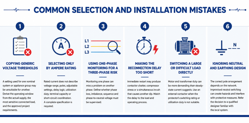
Common selection and installation mistakes of automatic re-closing voltage protector- Copying generic voltage thresholds: A setting used for one nominal system or appliance group may be unsuitable for another. Derive the operating window from the actual supply, the most sensitive connected load, and the approved project requirements.
- Selecting only by ampere rating: Rated current does not describe voltage range, poles, adjustable settings, delay logic, utilization duty, terminal capacity or short-circuit coordination. A complete specification is required.
- Using one-phase monitoring for a three-phase risk: Monitoring one phase can miss a problem on another phase. Define whether phase loss, imbalance, sequence and phase-to-neutral voltage must be supervised.
- Making the reconnection delay too short: Immediate restart may produce contactor chatter, compressor stress or a simultaneous inrush that causes another dip. Match the delay to the load and operating process.
- Switching a large or difficult load directly: Motor and transformer duty can be more demanding than steady-state current suggests. Use an external contactor when the protector’s switching rating or utilization duty is not suitable.
- Ignoring neutral and earthing design: The correct pole arrangement depends on the network. Improvised neutral switching can create hazards and interfere with protective measures. Refer the decision to a qualified designer familiar with the local system.
Maintenance and Troubleshooting in Service
A voltage protector normally requires little routine intervention, but it should still be included in the panel inspection plan. Check for discoloration, heat damage, loose terminals, dust accumulation, cracked housings and abnormal display values. Compare the displayed voltage with a calibrated instrument when readings appear doubtful. Thermal imaging under representative load can help reveal a poor terminal connection, although it does not replace torque checks performed under safe isolated conditions.
Keep a record of trip events where operational continuity matters. The time, displayed voltage, affected phase, connected load and recovery time can distinguish a supply-quality issue from a load-related voltage drop. Several trips at the same production time may indicate feeder demand. Random high and low readings across single-phase circuits may point toward a neutral problem. Trips only during generator operation may indicate AVR settings, frequency variation or poor generator/load matching.
| Observed symptom | Possible causes to investigate | Useful checks |
|---|---|---|
| Trips immediately after installation | Wrong nominal-voltage model, wiring error, threshold set too close to normal supply | Verify model, line/neutral connections, measured voltage and setting schedule |
| Repeated trip and reconnect cycle | Insufficient hysteresis, unstable supply, restart inrush causing another dip | Record voltage during restart; review recovery level and delay |
| Display is on but load remains off | Active fault, delay still counting, damaged contact, external contactor/control issue | Read status indication and test control circuit according to the manual |
| One phase shows abnormal voltage | Loose phase or neutral, phase imbalance, upstream connection fault | Isolate safely and inspect all conductors; measure every relevant phase |
| Terminal temperature is high | Loose termination, unsuitable conductor, overload, poor enclosure ventilation | Measure load current, inspect conductor preparation and verify specified torque |
Do not repeatedly reset or bypass a protector until the cause is known. Bypassing removes the protection at the moment the system may be demonstrating a genuine fault. If the device has switched a severe or repeated load, inspect its contacts and connected conductors according to the manufacturer’s service instructions. Replace a unit that shows heat damage, unreliable switching or readings outside its declared accuracy rather than attempting an unapproved repair.
Settings should also be controlled. For adjustable models, record the approved values during commissioning and restrict unauthorized changes. If equipment is added, the supply changes, or the panel is exported to a market with a different nominal voltage, review the entire setting schedule. A protector that was correctly configured for the original installation may be inappropriate after a system modification.
Często zadawane pytania
Dlaczego zabezpieczenie czeka przed ponownym podłączeniem obciążenia?
Opóźnienie potwierdza, że napięcie powróciło do normy i zapobiega szybkiemu cyklicznemu przełączaniu. Może również zapewnić czas ponownego uruchomienia sprężarek i zmniejszyć prawdopodobieństwo, że jednoczesny prąd rozruchowy ponownie obniży napięcie zasilania.
Czy może chronić przed utratą przewodu neutralnego?
Może ograniczyć narażenie, jeśli monitoruje napięcia fazowe względem przewodu neutralnego, których dotyczy problem, i odłącza zasilanie, gdy opuszczą one dopuszczalny zakres. Nie może naprawić uszkodzenia przewodu neutralnego, a układ monitorujący musi obejmować wszystkie istotne fazy.
Czy zabezpieczenie pod/nadnapięciowe to to samo co stabilizator napięcia?
Nie. Ochronnik odłącza obciążenie. Stabilizator lub AVR próbuje skorygować napięcie wyjściowe, kontynuując jego dostarczanie. Wybierz w zależności od tego, czy wymagane jest wyłączenie, czy ciągłe regulowane zasilanie.
Jak wybrać wartość natężenia prądu w amperach?
Określ maksymalny prąd, jaki będzie przewodzić urządzenie, uwzględnij obciążenie robocze i prąd rozruchowy, dobierz odpowiednią wartość znamionową z wymaganymi zaciskami i warunkami instalacji oraz skoordynuj ją z zabezpieczeniem zwarciowym po stronie zasilania. Użyj zewnętrznego stycznika, gdy bezpośrednie przełączanie jest nieodpowiednie.
Jakiego opóźnienia ponownego połączenia powinienem użyć?
Use the connected equipment manufacturer’s requirement and the process risk assessment. General lighting may accept a short delay; compressors and staged systems may need substantially longer or sequenced reconnection.
Dlaczego zabezpieczenie ciągle się wyłącza?
Możliwe przyczyny to rzeczywiste wahania zasilania, poluzowany przewód neutralny, przeciążony przewód zasilający, problemy z regulacją generatora, nieprawidłowe ustawienia, błędy w okablowaniu lub niedopasowanie urządzenia/obciążenia. Zmierz i zdiagnozuj system przed poszerzeniem progów.
Choose the Protection Boundary Before the Product Variant
An over and under voltage protector is most effective when its operating window is defined precisely. Selection becomes a practical sequence: establish the nominal system and monitored conductors, understand the load, choose direct switching or contactor control, set coordinated trip and recovery values, choose a safe reconnection delay, verify poles and neutral design, and test the completed panel under controlled conditions.
For a model recommendation, send JUTRION the nominal voltage and frequency, phase and neutral arrangement, load current and type, required thresholds and delay, pole configuration, upstream protective device, installation conditions, certification market and order quantity. The JRGQ-63, JQGQ-63 and JUGQ-63 ranges can then be compared against the actual project instead of selected from current rating alone.
