

Guia de Seleção de RCBO para Circuitos Reais: Tipo A/AC, 30mA, Curvas B/C e Polos
Um pedido de “32 A, 30 mA RCBO” não está pronto para encomenda. Identifica uma classe de corrente de carga e um limiar de corrente residual, mas não identifica a forma de onda da falha, a corrente de arranque, o limite do cabo, os condutores de alimentação ou a corrente de curto-circuito disponível. Os mesmos dois números poderiam descrever um circuito de tomadas geral, um conjunto de drivers LED ou um alimentador de inversor — e esses circuitos podem precisar de RCBOs diferentes.
A resposta prática é escolher o RCBO em torno da função de proteção. Para um circuito final moderno típico, Tipo A e 30 mA são frequentemente o ponto de partida. A escolha final ainda depende de se a carga produz fuga eletrónica, se a curva B consegue tolerar o arranque, quais condutores devem ser desligados e se 6 kA é suficiente no quadro.
Este guia segue três ficheiros de projeto em vez de uma sequência de catálogo. Cada projeto começa com um risco diferente e termina com uma descrição completa de RCBO que um empreiteiro, construtor de quadros ou distribuidor pode realmente utilizar.
Três Circuitos Que Não Devem Receber o Mesmo RCBO
| Ficheiro de projeto | Principal incerteza | Ponto de partida provável | Decisão que controla o resultado |
|---|---|---|---|
| Circuito de tomadas de escritório | Cargas eletrónicas futuras e continuidade | Tipo A, 30 mA, RCBO individual | Capacidade do cabo, nível de falha e interface do quadro |
| Iluminação LED e pequeno quadro de bomba | Corrente de arranque curta | Tipo A, 30 mA, curva B ou C | Inrush medido/declarado versus condições de desconexão de falha |
| Circuito trifásico alimentado por inversor | Forma de onda da corrente residual, potência reversa e neutro | Tipo A/F/B definido pelo equipamento e 3P/3P+N/4P | Instruções do conversor, topologia de alimentação e aprovação bidirecional |
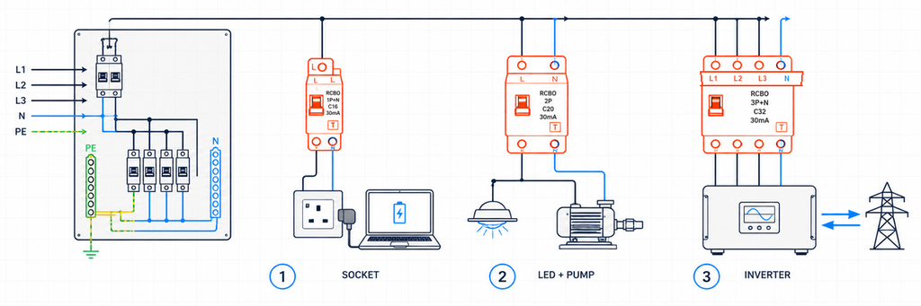
Três circuitos finais diferentes que exigem seleção de RCBO com base na sua carga real e disposição dos condutoresEstes exemplos são ilustrativos, não registos de projetos JUTRION concluídos. O seu objetivo é mostrar como um parâmetro muda porque o circuito muda.
Ficheiro de Projeto 1: Um Circuito de Tomadas de Escritório
O primeiro circuito alimenta tomadas gerais em um escritório de 230 V. Atualmente, os equipamentos conectados incluem laptops, monitores, carregadores e uma impressora. Amanhã, os ocupantes podem conectar diferentes aparelhos eletrônicos. Portanto, o projetista não pode garantir que o circuito permanecerá uma carga AC senoidal simples.
O Tipo A é o ponto de partida defensável
O Tipo AC responde à corrente residual alternada sinusoidal. O Tipo A também responde à corrente residual DC pulsante. A eletrónica monofásica moderna contém comumente retificadores e fontes de alimentação comutadas, pelo que o Tipo A é normalmente o ponto de partida mais prático para um circuito de tomadas não especificado.
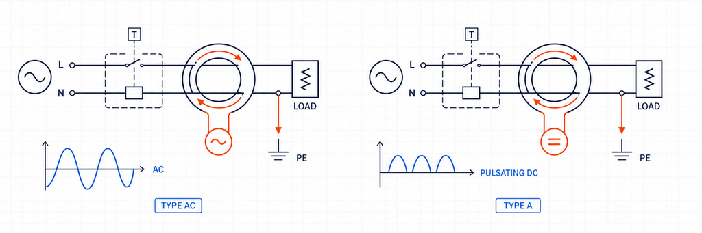
Comparação da forma de onda da corrente residual entre RCBO Tipo AC e Tipo AO Tipo A não é um substituto universal para todos os tipos de RCD. Equipamentos capazes de produzir DC suave ou correntes residuais de frequência mista específicas podem exigir Tipo F, Tipo B ou outra disposição declarada. Para um circuito de tomadas de escritório geral, no entanto, o Tipo A aborda uma população de cargas mais realista do que o Tipo AC.
Por que 30 mA e 20 A respondem a perguntas diferentes
A especificação do escritório propõe uma classificação de corrente residual de 30 mA para proteção adicional sob as regras de instalação aplicáveis. Esse valor de 30 mA é IΔn; descreve a função de corrente residual. Não descreve a corrente de carga que o circuito pode transportar.
Suponha que a corrente de projeto calculada seja 17,2 A e o cabo instalado tenha uma capacidade de corrente corrigida de 24 A. Um dispositivo de 20 A atende à relação inicial de proteção do condutor:
Ib ≤ In ≤ Iz
17,2 A ≤ 20 A ≤ 24 A
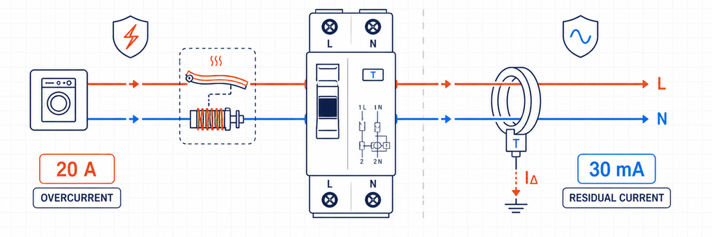
Proteção contra sobrecorrente de RCBO 20 amp comparada com proteção de corrente residual de 30 milliampAqui, Ib é a corrente de projeto, In é a corrente nominal do RCBO e Iz é a capacidade corrigida do cabo. Temperatura ambiente, agrupamento, isolamento, método de instalação, harmónicos e regras nacionais já devem estar refletidos em Iz. Escolher 25 A porque é o próximo tamanho de catálogo excederia a capacidade declarada do cabo.
RCBOs individuais protegem a continuidade, bem como as pessoas
Se vários circuitos de escritório partilharem um único RCCB, a fuga dos seus filtros eletrónicos acumula-se no dispositivo partilhado. Um evento de falha à terra também pode desligar todos os MCB a jusante. RCBOs individuais dividem a fuga por circuito e geralmente contêm um disparo de corrente residual no ramo afetado. Isso facilita a localização da falha e reduz a perda desnecessária de serviço.
A arquitetura não elimina o planeamento de fuga. A corrente normal do condutor de proteção ainda precisa de margem abaixo do limiar do dispositivo, particularmente onde muitas fontes de alimentação de TI ou cabos longos estão conectados.
O resultado do escritório
230 V AC, RCBO 1P+N, 20 A, Tipo A, 30 mA, curva B ou C sujeita a verificação de inrush e falha, capacidade de rutura acima do nível de falha do quadro medido/calculado, compatível com a barra coletora declarada da unidade de consumo.
A curva e a capacidade de rutura permanecem em aberto porque nenhuma pode ser escolhida apenas a partir de “tomadas de escritório”.
Ficheiro de Projeto 2: Iluminação LED Junto a uma Pequena Bomba
O segundo painel contém dois circuitos de saída com corrente normal semelhante. Um alimenta um grupo de drivers LED; o outro alimenta uma pequena bomba de arranque direto. Ambos podem produzir um breve pico de corrente durante a energização, mas a fonte e a duração desse pico diferem.
Curva B versus curva C é uma decisão de inrush e caminho de falha
Para características comuns de minidisjuntores IEC, a curva B tipicamente tem uma faixa de operação instantânea em torno de 3–5 vezes In, enquanto a curva C é em torno de 5–10 vezes In. A curva D, frequentemente em torno de 10–20 vezes In, é reservada para deveres de inrush mais elevados que foram especificamente projetados. A operação exata deve ser verificada contra os dados do produto aplicáveis.
Um RCBO de curva C pode tolerar uma corrente de arranque de curta duração maior antes que o seu elemento magnético opere. Isso não o torna uma escolha de uso geral melhor. O limiar mais elevado também significa que o circuito deve fornecer mais corrente de falha para garantir a desconexão instantânea.
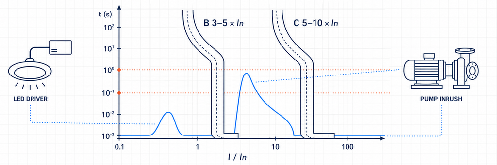
Faixas de disparo instantâneo de RCBO de curva B e curva C comparadas com a corrente de inrush de driver LED e bomba| Evidência do circuito | O que isso sugere | O que deve ser verificado a seguir |
|---|---|---|
| Pico de partida baixo ou controlado | A curva B pode permanecer adequada | Curva do fabricante e eventos de comutação normais |
| Pico curto e repetível acima da região magnética B | Considerar a curva C | Condições de loop de falta/desconexão e proteção de cabos |
| Inrush muito elevado de transformador ou motor | Solução C/D projetada ou método de partida diferente | Corrente de falta disponível, coordenação e proteção de equipamentos |
| O disparo ocorre após minutos de funcionamento | Provavelmente sobrecarga térmica e não inrush | Corrente de carga, temperatura do invólucro, terminais e cabo |
| A indicação de disparo mostra atuação por corrente residual | Alterar B para C não resolverá | Fuga, isolamento, humidade, encaminhamento do neutro e tipo de RCD |
Esta distinção evita um erro de diagnóstico comum. Um RCBO de curva B e um de curva C com a mesma marcação de 30 mA têm a mesma sensibilidade nominal à corrente residual. A letra da curva pertence à secção de sobrecorrente; não torna o RCBO mais tolerante a fugas à terra.
Drivers de LED e motores de bombas também alteram a questão do tipo de RCD
Os drivers de LED contêm eletrónica, pelo que o Tipo A é uma base sensata. Um circuito convencional de motor monofásico pode também incluir um controlador eletrónico, arrancador suave ou variador de velocidade. Uma vez introduzida eletrónica de potência, as instruções do equipamento — e não a palavra “motor” — determinam se o Tipo A continua adequado ou se é necessário o comportamento Tipo F/B.
Os dois resultados do circuito
Após verificar um inrush modesto do driver de LED e corrente de falta adequada, o circuito de iluminação pode ficar como:
230 V AC, 1P+N, 16 A, Tipo A, 30 mA, curva B, 6 kA quando a corrente de falta prospetiva verificada estiver abaixo dessa classificação.
Se o registo de partida da bomba exceder a região da curva B mas o circuito satisfizer os requisitos de desconexão da curva C, o circuito da bomba pode ficar como:
230 V AC, 1P+N ou 2P conforme necessário, 16 A, Tipo A (ou tipo especificado pelo equipamento), 30 mA quando necessário, curva C, capacidade de corte compatível com o nível de falta do quadro.
A diferença não foi “iluminação versus motor” pelo rótulo. Foi o comportamento de partida medido ou declarado, a forma de onda da corrente residual e o caminho de falta.
Ficheiro de Projeto 3: Um Circuito Trifásico com Suporte de Inversor
O terceiro projeto liga um sistema trifásico de eletrónica de potência. Pode importar energia, exportar energia ou operar de forma diferente quando uma fonte de backup está ativa. Um atalho de catálogo como “tetrapolar, Tipo B” é inseguro porque o design do conversor e a topologia de alimentação ainda não foram estabelecidos.
Deixar a documentação do conversor definir o tipo de corrente residual
O Tipo F estende o comportamento do Tipo A para condições definidas de frequência mista associadas a cargas selecionadas de inversores monofásicos. O Tipo B cobre uma gama mais ampla de corrente residual, incluindo DC suave sob as suas características aplicáveis. Alguns carregadores de VE e inversores incorporam monitorização de corrente contínua residual; outros exigem um dispositivo a montante específico.
A escolha não pode ser feita apenas pela categoria do produto. Confirmar:
- a forma de onda da corrente residual que o equipamento pode produzir;
- se a deteção de corrente residual DC é interna;
- o requisito exato de RCD/RCBO a montante nas instruções do equipamento;
- coordenação com qualquer dispositivo de corrente residual a montante;
- regras nacionais para a aplicação.
Não confundir um RCBO Tipo B com um RCBO de curva B. O Tipo B descreve a capacidade de deteção de corrente residual. A curva B descreve a resposta instantânea de sobrecorrente. Um produto pode ser Tipo B com curva C.
Os polos seguem os condutores, não o nome da carga
Uma carga trifásica de três fios sem neutro pode usar uma disposição 3P. Um sistema trifásico de quatro fios com neutro requer 3P+N ou 4P conforme definido pelo produto, sistema e regras de instalação. A ficha técnica deve mostrar se o neutro é comutado, sólido ou protegido contra sobrecorrente.
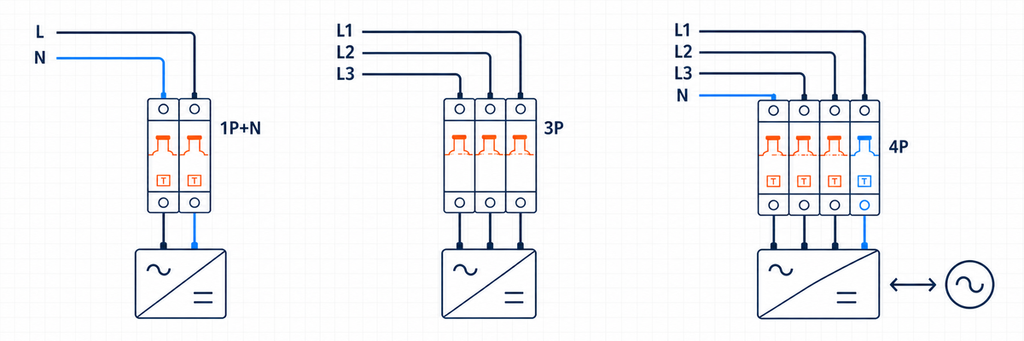
RCBO 1P mais N, disposições de polos 3P e 4P para circuitos com suporte de inversor| Disposição | Sistema provável | Confirmação necessária |
|---|---|---|
| 1P+N | Linha e neutro monofásicos | Comutação do neutro, direção linha/carga e posição da barra de barramentos |
| 2P | Monofásico com desconexão de dois polos | Quais polos são comutados e protegidos contra sobrecorrente |
| 3P | Trifásico sem neutro | Sem necessidade de operação ou detecção de neutro |
| 3P+N | Trifásico com neutro | Comportamento de comutação/proteção do neutro |
| 4P | Trifásico, quatro fios com operação de quatro polos declarada | Operação simultânea e compatibilidade do sistema |
Cada condutor exigido pelo arranjo de detecção de corrente residual deve seguir o diagrama do fabricante. Um neutro emprestado ou desviado cria desequilíbrio e pode fazer o dispositivo disparar mesmo quando as cargas em si estão saudáveis.
Potência reversa requer um dispositivo bidirecional declarado
Equipamentos solares, baterias e veículo para rede podem alimentar o circuito na direção oposta a uma carga convencional. Um interruptor manual não prova a adequação bidirecional. Verifique a direção de fornecimento permitida, a orientação dos terminais, o desempenho em curto-circuito em cada direção, o comportamento do neutro e o sistema de placa aprovado.
O RCBO é apenas uma parte desta cadeia de proteção. Ele não substitui a isolação necessária, funções anti-ilhamento, proteção contra surtos ou identificação segura da fonte.
O resultado do circuito do inversor
400 V AC, 3P/3P+N/4P de acordo com o sistema de condutores atual, tipo de corrente residual exigido pelo fabricante do conversor, sensibilidade exigida pelas regras da aplicação, curva C/D apenas após a inicialização e verificação de falhas, uso bidirecional declarado onde a potência pode reverter, e capacidade de interrupção acima do nível de falha do projeto.
Esta especificação é mais longa porque o sistema possui mais interfaces. Abreviá-la para “4P C32 30 mA” descartaria as decisões mais propensas a afetar a compatibilidade.
O Decodificador de Classificações: O que Cada Marcação Prova
Os três arquivos do projeto agora podem ser reduzidos a uma tabela de decodificação. Cada classificação fecha um risco diferente; nenhum valor único pode substituir outro.
| Campo do RCBO | Significado de engenharia | Evidência do projeto | Falha se ignorado |
|---|---|---|---|
| Tensão/frequência nominal | Condições de fornecimento para operação declarada | Desenhos do sistema e dados do equipamento | Operação incorreta ou classificação inválida |
| Em (A) | Corrente nominal da seção de sobrecorrente | Ib, Iz corrigido e carga de serviço | Disparos por sobrecarga ou cabo não protegido |
| Curva B/C/D | Resposta magnética instantânea | Dados de corrente de partida e de falha | Disparos de partida indesejados ou limpeza inadequada de falhas |
| Tipo AC/A/F/B | Capacidade de forma de onda de corrente residual | Topologia de carga e instruções do fabricante | Falha em responder corretamente à possível forma de onda |
| IΔn (mA) | Sensibilidade à corrente residual | Objetivo de proteção e regra de instalação | Nível de proteção incorreto ou continuidade deficiente |
| Polos/neutro | Condutores detectados, comutados e protegidos | Diagrama unifilar e sistema de aterramento | Isolação, detecção ou operação do neutro incorretas |
| Capacidade de interrupção (kA) | Dever máximo de interrupção de curto-circuito declarado | Corrente de curto-circuito prospectiva | Dispositivo utilizado além de sua capacidade de interrupção testada |
| Interface de direção/placa | Orientação de alimentação e compatibilidade física | Ficha técnica atual e declaração da placa | Instalação inválida, incompatibilidade de barramento ou problema de potência reversa |
IEC 61009-1:2024 fornece requisitos de produto e testes para RCBOs para uso doméstico e similar dentro de seu escopo declarado. Não substitui o código nacional de instalação. A conformidade do produto responde se o RCBO atende aos requisitos de produto declarados; a conformidade da instalação responde se esse dispositivo está corretamente aplicado no circuito.
Por que 10, 30, 100 e 300 mA Não São Graus de Qualidade
Um IΔn mais baixo é mais sensível, mas “mais sensível” não significa “melhor para cada posição.” Dispositivos de dez miliamperes podem ser selecionados para funções locais ou de maior sensibilidade. Trinta miliamperes é amplamente utilizado para proteção adicional em circuitos finais. Valores de cem e 300 mA podem servir para funções selecionadas a montante, de equipamentos ou de risco de incêndio.
Um dispositivo de 100 ou 300 mA a montante não substitui a proteção de 30 mA a jusante onde 30 mA é necessário. Inversamente, instalar proteção instantânea de 30 mA em ambos os níveis a montante e a jusante pode comprometer a seletividade, pois ambos os dispositivos veem o mesmo desequilíbrio de falha à terra.
Onde a proteção contra corrente residual a montante é utilizada, coordene tanto o limiar quanto o tempo de operação. Uma função seletiva/com atraso de tempo pertence ao nível permitido pelo projeto da instalação; não deve atrasar uma função de proteção de circuito final que deve operar prontamente.
6 kA ou 10 kA É uma Decisão de Localização
A capacidade de interrupção deve ser pelo menos a corrente de curto-circuito prospectiva no ponto de instalação do RCBO sob suas condições declaradas. Uma placa próxima a um transformador pode ter um nível de falha mais alto do que um circuito final distante, mesmo quando o edifício distante é fisicamente maior.
Use um cálculo, medição ou registro confiável do nível de falha do projeto. Se a proteção de backup a montante for proposta, use uma combinação testada ou declarada pelo fabricante. Um disjuntor a montante com uma grande classificação de interrupção não transfere automaticamente essa classificação para um RCBO a jusante.
A proteção de backup e a seletividade também são diferentes. Uma combinação pode interromper uma alta falha com segurança enquanto ambos os dispositivos se abrem. Se a continuidade exigir apenas que o circuito a jusante se desconecte, obtenha evidências de seletividade para a faixa de corrente relevante.
Transforme Dados do Projeto em uma Descrição Ordenável
Antes de selecionar um modelo, reúna um breve registro do projeto:
- país/mercado e requisitos de instalação aplicáveis;
- tensão do sistema, frequência e arranjo de aterramento;
- condutores monofásicos ou trifásicos, incluindo neutro;
- descrição da carga, topologia do conversor eletrônico e corrente de partida;
- corrente de projeto e capacidade de cabo corrigida;
- objetivo de proteção contra corrente residual requerida;
- corrente de curto-circuito prospectiva na placa;
- direção do fluxo de potência em cada modo de operação;
- modelo de unidade consumidora/placa de distribuição, barramento e largura de módulo disponível;
- requisitos de terminal, ambientais, de indicação e de acessórios.
Em seguida, escreva a especificação em uma linha:
[voltage/frequency], [poles and neutral arrangement], [In], [curve], [Type AC/A/F/B], [IΔn], [breaking capacity], [supply direction], [product standard/market approval], [board and busbar interface].
Esta linha é mais útil do que pedir a um fornecedor “um bom RCBO.” Ela fornece às equipes de engenharia e compras a mesma referência e expõe informações faltantes antes que amostras ou produção sejam comprometidas.
Valide o RCBO Selecionado na Placa Real
Um conjunto de classificação tecnicamente correto ainda pode falhar na interface de montagem. Antes que um distribuidor aceite uma faixa de substituição ou um OEM libere uma unidade de consumo, o RCBO selecionado deve ser verificado no invólucro pretendido com o barramento, condutores e acessórios pretendidos.
Ajuste mecânico e de fiação
Confirme a largura do módulo, engajamento do trilho DIN, posição do dente do barramento, localização do neutro e acesso ao terminal. Um dispositivo descrito como 1P+N pode usar um fio neutro flutuante, um terminal neutro em um lado específico ou um passo de barramento diferente de outro dispositivo 1P+N. Dimensões frontais semelhantes não provam intercambiabilidade.
Verifique o material do condutor permitido, seção transversal rígida/flexível e requisitos de terminais. Prepare os condutores conforme declarado e aplique o torque de terminal especificado. Uma conexão solta pode gerar calor sem exceder a corrente de carga do circuito, enquanto um torque excessivo pode danificar o terminal ou o condutor.
Evidência funcional
A comissionamento deve distinguir os dois sistemas de disparo. Onde o dispositivo fornece indicação separada, registre se uma operação de teste é relatada como corrente residual ou sobrecarga. Verifique a função do botão de teste nas condições de fornecimento declaradas pelo fabricante e, em seguida, complete os testes de instalação exigidos pelas regras aplicáveis. O botão de teste verifica um caminho funcional interno; não mede o loop completo de falha à terra, condição de isolamento ou todos os requisitos de tempo de disparo.
Para circuitos com muitas cargas eletrônicas, registre a corrente de carga normal, pico de partida e vazamento em repouso após a comissionamento. Esses três valores criam uma linha de base. Se os disparos aparecerem meses depois, a manutenção pode comparar novas evidências com a condição original em vez de substituir dispositivos por tentativa e erro.
Temperatura e agrupamento
Vários dispositivos modulares carregados montados lado a lado podem operar em um ambiente local mais quente do que a temperatura ambiente sugere. A ventilação do invólucro, componentes adjacentes que produzem calor, tamanho do condutor e carga sustentada afetam a temperatura. Aplique as instruções de desclassificação ou espaçamento do fabricante onde relevante; não responda a um disparo térmico aumentando a classificação em ampères sem reavaliar a proteção do cabo.
Controle de lote e documentação
Para um OEM ou distribuidor, bloqueie os atributos aprovados na lista de materiais: modelo exato, curva, tipo de corrente residual, IΔn, polos, capacidade de interrupção, arranjo de terminais, aprovação e acessórios compatíveis. Um substituto que corresponda apenas à corrente e largura pode mudar silenciosamente o tipo de forma de onda ou o comportamento do neutro.
Mantenha a ficha técnica atual, documentos de declaração/certificação exigidos pelo mercado-alvo, diagrama de fiação e identificação do lote com o registro de amostra aprovada. Isso transforma a seleção em um controle de produção repetível, em vez de uma conversa de engenharia única.
Separe a Conformidade do Produto da Conformidade da Instalação
Uma marcação IEC é importante, mas não decide onde ou como o RCBO pode ser instalado. IEC 61009-1:2024 define requisitos gerais e testes para RCBOs para uso doméstico e similar dentro de seu escopo declarado. As regras nacionais de fiação, regulamentações locais, especificações do projeto e a autoridade competente determinam a aplicação da instalação.
| Pergunta | De onde vem a resposta | Exemplo |
|---|---|---|
| O RCBO foi avaliado como um produto? | Padrão do produto, certificação e documentação do fabricante | Tensão declarada, corrente, IΔn, tipo e capacidade de curto-circuito |
| A proteção contra corrente residual é necessária aqui? | Regras nacionais de instalação e projeto | Tomada, circuito externo, local úmido ou equipamento especial |
| Qual tipo de corrente residual é permitido? | Regras de instalação mais instruções de equipamento | Restrição ao Tipo AC ou requisito criado por equipamentos conversores |
| O circuito desconectará a tempo? | Cálculo/teste de instalação e característica do dispositivo | Condições do laço de falha para uma curva B/C/D escolhida |
| O RCBO pode se encaixar neste quadro? | Declarações do sistema de quadro e do fabricante do dispositivo | Barramento, terminais, posição neutra e classificação do invólucro |
Esta distinção é importante em projetos de exportação. Uma configuração de produto aceita em um mercado pode exigir um tipo de corrente residual diferente, arranjo de polos, marca de aprovação ou sistema de quadro de distribuição em outro. Não converta uma regra nacional em uma reivindicação universal da IEC e não assuma que um certificado de componente aprova o painel completo.
A Guia de seleção de RCD da BEAMA é uma fonte autoritativa útil para raciocínio sobre forma de onda e aplicação, particularmente em relação a cargas eletrônicas modernas. Suas referências de instalação regionais ainda precisam ser aplicadas dentro de sua própria jurisdição. Para outro mercado, use as regras nacionais relevantes e instruções de equipamento.
Onde um RCBO se encaixa—e onde não se encaixa
Um RCBO combina proteção contra corrente residual com proteção contra sobrecarga e curto-circuito. Um RCCB normalmente requer proteção contra sobrecorrente coordenada, enquanto um MCB não fornece proteção contra corrente residual. A arquitetura RCBO-por-circuito muitas vezes melhora a continuidade e a isolação de falhas, mas ainda deve coordenar com a proteção a montante e o quadro de distribuição.
Um RCBO normalmente não reconhece assinaturas de arco perigosas. Se a mitigação de falha de arco faz parte do projeto, use o guia AFDD da JUTRION para mapear as funções de proteção necessárias. RCBOs também não substituem SPDs, isoladores ou proteção específica de equipamento simplesmente porque várias funções compartilham um invólucro.
Escolha a Função de Proteção Antes do Número do Catálogo
O circuito de escritório começou com cargas eletrônicas imprevisíveis, então a proteção Tipo A e individual de 30 mA controlou a decisão. Os circuitos de iluminação e bomba começaram com comportamento de partida, então a escolha da curva B/C dependia tanto da corrente de partida quanto da corrente de falha. O circuito do inversor começou com forma de onda, topologia do condutor e potência reversa, então as instruções de equipamento e a aprovação bidirecional eram importantes antes da amperagem.
Essa é a regra de seleção transferível: identifique a falha que o RCBO deve detectar, comprove o cabo e o caminho da falha, e então complete a interface física. Um número de catálogo correto é o resultado desse processo, não o ponto de partida.
A JUTRION oferece RCBOs para distribuição monofásica e trifásica com múltiplas combinações de polo, corrente, sensibilidade, tipo de forma de onda, curva e capacidade de interrupção. Compartilhe o registro do projeto acima ao solicitar suporte de seleção para que o modelo proposto possa ser verificado em relação ao circuito real.
Perguntas Frequentes
Devo escolher um RCBO Tipo A ou Tipo AC?
Tipo AC detecta corrente residual alternada senoidal, enquanto Tipo A também detecta corrente residual pulsante DC. Como muitos aparelhos modernos contêm retificadores e fontes chaveadas, o Tipo A é frequentemente o ponto de partida mais prático para circuitos gerais de tomadas, iluminação e aparelhos. A escolha final deve seguir as instruções do equipamento conectado e as normas de instalação aplicáveis.
Um RCBO de 30 mA é sempre a escolha correta?
Não. Um valor de corrente residual de 30 mA é comumente utilizado onde proteção adicional é necessária, mas não é um valor universal para todos os circuitos. As regras de aplicação, a expectativa de fuga de corrente, a seletividade a montante e os requisitos do equipamento devem ser verificados. O valor de 30 mA também não determina a classificação de corrente de carga do RCBO.
Qual é a diferença entre um RCBO Tipo B e um RCBO de curva B?
Eles descrevem funções diferentes. Tipo B identifica a capacidade de detecção de corrente residual, incluindo DC contínua dentro das características declaradas do dispositivo. Curva B identifica a faixa de atuação instantânea da seção de sobrecorrente. Um RCBO pode, portanto, ter comportamento de corrente residual Tipo B e característica de sobrecorrente curva C.
Quando devo escolher um RCBO de curva C em vez de curva B?
Considere a curva C quando a corrente de partida verificada de equipamentos como motores, transformadores ou grupos de drivers de LED puder entrar na região de operação magnética da curva B. A curva C não é uma cura automática para disparos indesejados: o circuito ainda deve fornecer corrente de falha suficiente para o tempo de desconexão requerido, e a indicação de disparo deve primeiro confirmar que o evento é sobrecorrente e não corrente residual.
Preciso de um RCBO 1P+N, 2P, 3P ou 4P?
Escolha a disposição dos polos com base nos condutores de alimentação reais e no método de desconexão requerido. Um circuito monofásico de linha e neutro pode usar 1P+N ou 2P de acordo com o produto e o design da instalação. Circuitos trifásicos podem exigir 3P, 3P+N ou 4P dependendo de haver um neutro presente e como ele deve ser comutado e detectado. Sempre siga o diagrama de fiação do fabricante.
Posso usar um RCBO Tipo A padrão com um inversor?
Somente quando o fabricante do inversor e as regras de instalação aplicáveis permitirem. Equipamentos de eletrônica de potência podem exigir Tipo A, Tipo F, Tipo B ou uma disposição coordenada com monitoramento de corrente contínua residual embutido. Também verifique a configuração dos polos, o tratamento do neutro, a direção de alimentação permitida e a operação bidirecional declarada onde a energia pode fluir de volta para a rede.
Referências Técnicas
