

Como Dimensionar um ATS para Inversores Solares Híbridos: Comutação de Backup Grid-Tied vs. Off-Grid Explicada
Para dimensionar um ATS para um inversor solar híbrido, primeiro identifique o que o comutador irá realmente transferir. Não selecione apenas com base nos quilowatts do arranjo PV. No ponto instalado, compare a corrente máxima de passagem pela rede, a corrente máxima de saída de backup do inversor e a corrente de projeto do painel de carga transferida. Use a maior corrente que pode passar legitimamente pelo ATS, depois verifique o arranjo de polos, a capacidade de curto-circuito, a categoria de utilização, a lógica de transferência e a compatibilidade com a arquitetura de backup aprovada do inversor.
Essa distinção é importante porque “grid-tied”, “híbrido” e “off-grid” descrevem comportamentos elétricos diferentes. Um inversor PV convencional conectado à rede normalmente para de fornecer energia durante uma falta prolongada da rede. Um inversor híbrido pode conter um relé de transferência interno e uma saída de backup dedicada. Um inversor off-grid pode formar seu próprio barramento AC e usar a rede ou um gerador apenas como entrada alternativa. Instalar o mesmo ATS genérico em todos os três sistemas pode causar disparos indesejados, cargas de backup inativas, comandos de transferência conflitantes ou um caminho paralelo inseguro.
Este guia explica como estabelecer o limite correto do ATS, calcular a corrente e especificar o arranjo de comutação para cada arquitetura. Ele complementa nosso guia geral guia de dimensionamento de comutador de transferência automática, com foco específico em sistemas solares híbridos e de backup com bateria.
Resposta Rápida: Qual Classificação Deve Controlar o Dimensionamento do ATS?
A corrente de controle depende da localização do ATS:
| Localização do ATS | Fontes sendo selecionadas | Base de corrente | Erro comum |
|---|---|---|---|
| Antes da entrada AC do inversor | Rede e gerador | Corrente máxima permitida de entrada AC ou passagem, demanda da carga transferida e limite da fonte | Dimensionamento apenas pela potência de saída do inversor em kW |
| Após a saída de backup | Saída de backup do inversor e bypass da rede | Corrente credível mais alta entregue ao painel de carga de backup | Usando kW do arranjo PV em vez da corrente do painel de backup |
| Limite de serviço de todo o edifício | Concessionária e fonte de ilhamento intencional | Cálculo de serviço/carga mais classificação aprovada da interface de backup | Adicionar um ATS genérico a um sistema que requer uma interface de backup listada |
| Barramento AC off-grid | Inversor e gerador ou bypass da concessionária | Corrente máxima de carga transferida e limites contínuos de ambas as fontes | Permitir que dois controladores independentes conectem fontes sem intertravamento coordenado |
O tamanho de quadro selecionado não deve ser inferior à corrente máxima de projeto através do comutador. No entanto, apenas os ampères não completam a especificação. O ATS final também deve ser adequado à tensão do sistema, número de fases, arranjo de neutro e aterramento, nível de falta esperado, método de transferência e regras de instalação aplicáveis.
Comece pela Arquitetura, Não pelo Catálogo de ATS
Antes de calcular a corrente, desenhe uma linha de cada fonte possível até as cargas. Marque o ponto de conexão da concessionária, entrada de rede do inversor, saída de backup do inversor, bateria, gerador, painel de cargas essenciais e cada dispositivo capaz de abrir ou fechar um caminho de fonte. Se o mecanismo de comutação, controlador, sensoriamento de fonte e intertravamento ainda não forem familiares, revise como funciona um comutador de transferência automática e como selecionar um antes de finalizar o diagrama unifilar. O desenho deve tornar impossível que a concessionária e uma fonte de ilhamento não sincronizada sejam conectadas juntas.
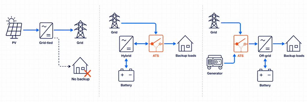
O Departamento de Energia dos EUA distingue inversores que seguem a rede, que requerem uma rede funcional, de inversores que formam a rede e podem operar quando a rede está indisponível. Ele também observa que inversores comuns conectados à rede se desconectam durante distúrbios maiores ou sustentados da rede. É por isso que um ATS não pode transformar um inversor padrão conectado à rede em uma fonte de backup. O backup intencional requer um inversor e um arranjo de isolamento especificamente projetados para operação em ilhamento.
Arquitetura 1: PV Convencional Conectado à Rede Sem Backup
Um inversor PV convencional conectado à rede opera em paralelo com a concessionária e exporta ou compensa energia enquanto a rede está estável. Durante uma falta, a proteção anti-ilhamento desconecta o inversor. Não há uma fonte AC alternativa estável para o ATS selecionar.
Nessa arquitetura, instalar um ATS entre a concessionária e a residência não faz o sistema PV continuar operando. O inversor ainda precisa de uma referência válida da rede e não é permitido energizar um circuito isolado, a menos que seja projetado e aprovado para formar essa ilha. Se for necessário backup para falta, a arquitetura do sistema deve mudar: tipicamente adicionando uma bateria compatível, função de inversor formador de rede, interface de backup e limite de carga essencial.
Arquitetura 2: Inversor Híbrido com um Dispositivo de Transferência Interno
Muitos inversores híbridos têm terminais separados de rede e backup. Internamente, um dispositivo de transferência isola a concessionária e fornece uma saída de backup designada a partir da bateria e do inversor durante uma interrupção. Neste caso, a documentação do inversor—não um diagrama genérico—define o arranjo de neutro permitido, dispositivos de proteção, tamanho do painel de backup, sequência de reconexão e se um ATS externo é permitido.
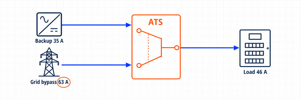
Um ATS adicional ainda pode servir a um propósito legítimo. Por exemplo, ele pode contornar um inversor com falha e reconectar o painel de cargas essenciais diretamente à concessionária. Nesse arranjo, o ATS não está criando o ilhamento solar. Ele está selecionando entre a saída de backup do inversor e um bypass da rede. A classificação de corrente do ATS deve, portanto, cobrir a corrente máxima disponível em qualquer um desses caminhos.
Algumas plataformas híbridas usam em vez disso um controlador de sistema dedicado ou interface de backup que já contém a função de transferência. Substituir ou duplicar essa função com um ATS de uso geral pode anular o monitoramento do sistema, controle de neutro, lógica anti-ilhamento ou certificação do fabricante. Trate “comutador de transferência interno”, “interface de backup” e “ATS de bypass externo” como três componentes diferentes até que o diagrama unifilar aprovado prove o contrário.
Arquitetura 3: Inversor Off-Grid ou Formador de Rede com Entrada AC Alternativa
Um inversor off-grid normalmente estabelece tensão e frequência para o barramento AC local. Uma concessionária ou gerador pode conectar-se a uma entrada AC para que o inversor/carregador possa transferir cargas, carregar a bateria ou suportar a energia. Muitos inversores/carregadores já contêm um relé de transferência interno. Se o projeto usar um ATS externo, ele pode selecionar concessionária versus gerador na entrada do inversor, ou saída do inversor versus uma fonte bypass no painel de carga.
Essas duas posições não são intercambiáveis. Um ATS no lado da entrada vê a corrente aceita e passada pelo inversor/carregador. Um ATS de bypass no lado da saída vê a corrente demandada pelas cargas transferidas. O controlador do lado da entrada também pode precisar de contatos de partida/parada do gerador, tempo de aquecimento, janelas de aceitação de tensão e frequência, e uma sequência de resfriamento. O dispositivo do lado da saída deve evitar realimentar a saída do inversor quando o bypass está ativo, a menos que o projeto do fabricante permita expressamente.
Os Quatro Valores de Corrente Que Você Deve Registrar
Uma planilha de seleção confiável registra quatro valores de corrente em vez de um único número de potência solar.
Corrente de Projeto das Cargas Transferidas
Esta é a corrente exigida pelas cargas conectadas a jusante do ATS. Não é automaticamente a classificação do serviço principal e não é automaticamente a classificação do inversor. Um comutador de transferência para todo o edifício pode transportar a demanda calculada do edifício. Um ATS de cargas essenciais pode transportar apenas refrigeração, iluminação, controles, comunicações, tomadas selecionadas e outros circuitos priorizados.
Use o cálculo de carga do projeto e o código elétrico aplicável. Considere cargas contínuas, motores, transformadores, compressores e operação simultânea. Se o descarte de carga fizer parte do projeto, documente quais cargas se desconectam antes de usar o valor reduzido.
Corrente Máxima de Saída de Backup do Inversor
Leia a ficha técnica ou manual de instalação do inversor. Prefira sua corrente máxima contínua de saída de backup declarada em vez de um cálculo a partir da potência nominal de marketing. Se apenas a potência aparente estiver disponível, os cálculos básicos de AC são:
Monofásico: I = S ÷ V
Trifásico: I = S ÷ (√3 × V)
Para uma saída monofásica de 10 kVA, 230 V, a corrente ideal é aproximadamente 43,5 A. Para uma saída trifásica de 30 kVA, 400 V, é aproximadamente 43,3 A por fase. Esses valores são pontos de partida, não permissão para ignorar o limite de corrente do fabricante, curva de sobrecarga, limite de desequilíbrio de fase ou desclassificação por temperatura ambiente.
Corrente de Passagem ou Bypass da Rede
Este é frequentemente o valor controlador. Um inversor híbrido classificado para 8 kW de saída de backup pode permitir que uma corrente de rede maior passe através de seu relé interno enquanto a concessionária estiver disponível. Da mesma forma, um caminho de bypass externo pode alimentar todo o painel de cargas essenciais diretamente da rede.
Se 63 A podem passar pelo ATS no modo rede, selecionar um ATS de 40 A porque o inversor produz apenas 8 kW está incorreto. Os contatos do interruptor e os terminais ainda suportam o caminho de 63 A. Registre a corrente máxima de entrada/transferência AC do inversor, a classificação do disjuntor bypass e o cálculo da carga a jusante, então use o projeto coordenado mais restritivo.
Corrente Máxima Permitida por Cada Fonte e Dispositivo de Proteção
O alimentador da concessionária, o disjuntor do gerador, a proteção de saída do inversor, os condutores e o dispositivo principal do quadro de distribuição estabelecem limites. O ATS não cria capacidade extra de fonte, e sua classificação de corrente não protege cabos por si só. Um interruptor de transferência classe PC normalmente depende de proteção de sobrecorrente coordenada a montante; um arranjo classe CB integra funções de disjuntor. Selecione e verifique toda a cadeia de proteção.
Um Método Prático de Dimensionamento de ATS para Inversores Híbridos
- Confirme que o inversor pode formar uma ilha. Se for somente PV e seguidor de rede, pare: não há fonte de backup válida para o ATS.
- Use a arquitetura aprovada pelo fabricante. Identifique a interface de backup necessária, o relé de transferência interno, o interruptor externo compatível ou o arranjo de bypass permitido.
- Marque a posição do ATS. Declare exatamente quais duas fontes se conectam à Fonte I e à Fonte II, e qual painel se conecta à saída comum.
- Defina as cargas transferidas. Use uma lista de cargas essenciais ou o cálculo de demanda de todo o edifício em vez de somar placas de identificação de aparelhos indiscriminadamente.
- Registre a corrente de saída de backup. Use a corrente máxima declarada e anote a capacidade de sobrecarga de curta duração separadamente.
- Registre a corrente de passagem ou bypass da rede. Verifique o limite de entrada do inversor, a classificação do relé interno, o alimentador de bypass e o dispositivo principal do painel.
- Selecione a corrente contínua. O ATS deve conduzir a corrente máxima credível em sua posição instalada, sujeito às regras do código, desclassificação, temperatura do invólucro e instruções do fabricante.
- Complete as verificações não relacionadas a ampères. Verifique tensão, frequência, fases, polos, tratamento de neutro, classificação de curto-circuito, categoria de utilização, tempo de transferência, sensoriamento, tensão de controle e intertravamento.
- Valide cada estado operacional. Revise a operação normal da rede, falha da rede, falha do inversor, bateria esgotada, operação do gerador, bypass de manutenção e retorno da rede.
Exemplo Prático: Inversor Híbrido de 8 kW com Bypass de Rede
Considere um sistema monofásico ilustrativo de 230 V com estes valores de projeto:
- Classificação de backup do inversor híbrido: 8 kVA contínuos
- Corrente máxima declarada de saída de backup: 35 A
- Corrente de passagem da rede permitida: 63 A
- Corrente de projeto do painel de cargas essenciais: 46 A quando a rede está disponível
- Limite de gerenciamento de carga no modo backup: 32 A
- Posição do ATS externo: saída de backup do inversor versus bypass direto da rede
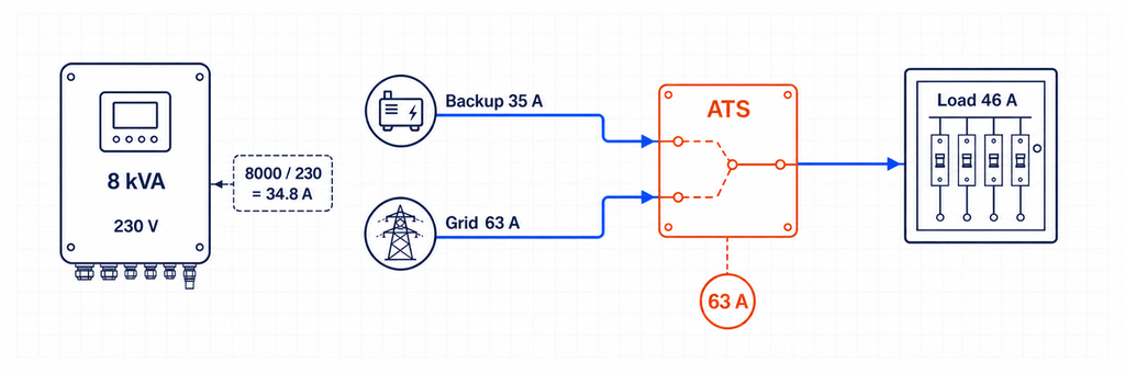
A corrente aproximada do inversor a partir da potência aparente é 8.000 ÷ 230 = 34,8 A, consistente com a saída declarada de 35 A. Mas um ATS de 40 A não é automaticamente adequado. No modo bypass da rede, o painel de carga essencial pode consumir 46 A e o caminho da fonte é permitido até 63 A.
Neste local, a seleção de corrente do ATS é controlada pelo caminho de bypass da rede e de cargas transferidas, não pela saída do inversor de 8 kVA. Uma classe de 63 A pode ser a classe de corrente mínima prática se todas as verificações aplicáveis de carga contínua, temperatura, invólucro, terminal e código local permitirem. Um quadro de 80 A pode ser selecionado onde o projeto coordenado, a desclassificação por temperatura ambiente, a terminação do condutor ou a norma do projeto exigirem mais margem. A resposta final não pode ser obtida apenas com 8 kW.
O controlador de gerenciamento de carga deve manter a demanda no modo backup dentro da capacidade de 35 A do inversor. Superdimensionar o ATS para 63 A ou 80 A não torna o inversor capaz de fornecer 46 A durante uma interrupção. Essa é uma restrição separada de energia e gerenciamento de potência.
Transferência de Toda a Casa ou Transferência de Cargas Essenciais?
Essa escolha altera tanto o tamanho do ATS quanto o comportamento do sistema. Um arranjo de transferência de toda a casa coloca o limite de backup em torno da maior parte ou de toda a distribuição do edifício. O ATS e a interface associada podem, portanto, precisar corresponder ao serviço ou à demanda calculada, mesmo quando o inversor pode fornecer apenas uma fração dessa corrente. O backup bem-sucedido de toda a casa geralmente depende de gerenciamento automático de carga que desconecta aquecimento de água, ar-condicionado de grande porte, carregamento de VE, cozimento elétrico ou outras cargas antes que o inversor seja sobrecarregado.
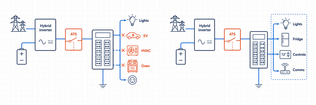
Um arranjo de carga essencial cria um painel a jusante menor. Apenas os circuitos selecionados transferem para a energia do inversor. Isso frequentemente permite uma classificação de corrente do ATS mais baixa, condutores menores e autonomia de bateria mais previsível. Também torna visível o limite de corrente no modo de backup: se o painel contém 32 A de demanda gerenciada, o projetista pode verificar isso em relação à saída declarada do inversor, em vez de esperar que os ocupantes evitem cargas simultâneas.
Use a seguinte decisão:
- Escolha um painel de carga essencial quando a saída do inversor é materialmente inferior à capacidade de serviço, a energia da bateria é limitada, ou a priorização de carga confiável é mais importante do que a conveniência.
- Considere a transferência para toda a casa quando o controlador de sistema aprovado o suporta, o inversor e a bateria podem sustentar a demanda pretendida, e a redução automática de carga é documentada.
- Não reduza a corrente do ATS apenas porque o software em modo de backup limita o inversor. Se os mesmos contatos suportam a demanda total em modo de rede, dimensione-os para esse caminho de rede.
Para aquisição, declare ambos os números: “corrente contínua do ATS na fronteira instalada” e “carga máxima permitida em modo de backup.” Eles respondem a perguntas diferentes e evitam que os instaladores tratem um interruptor superdimensionado como evidência de capacidade adequada do inversor.
Inversores Híbridos Trifásicos Precisam de Verificações Adicionais
O cálculo de corrente trifásica assume potência aparente balanceada. Painéis de backup reais podem estar desequilibrados, e alguns inversores híbridos impõem uma corrente máxima por fase ou um desequilíbrio máximo permitido entre fases. Por exemplo, um inversor trifásico nominal de 30 kVA, 400 V corresponde a aproximadamente 43,3 A por fase:
I = 30.000 ÷ (1,732 × 400) = 43,3 A por fase
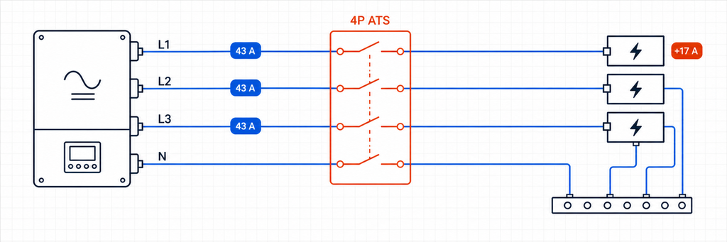
Esse resultado não prova que um ATS de 50 A seja adequado. Verifique se a classificação de passagem da rede é 63 A, 80 A ou outro valor; se o painel de backup pode concentrar cargas monofásicas em uma fase; e se o inversor pode energizar as três fases durante a operação em ilha. Uma carga de 4 kW adicionada a uma fase representa aproximadamente 17,4 A a 230 V, mesmo que o kVA trifásico total ainda pareça aceitável.
Elabore um cronograma de fases para as cargas essenciais. Mantenha grandes cargas monofásicas distribuídas sempre que possível e verifique a pior fase em vez de apenas a média. Se o inversor permitir 40 A em cada fase, mas o desvio da rede permitir 63 A, o ATS em uma fronteira de saída de backup/desvio da rede pode ainda exigir uma classe de corrente de 63 A. Os controles de carga em modo de backup devem então impedir que qualquer fase exceda o limite do inversor.
Também confirme o que acontece quando uma fase falha. Alguns controladores de ATS transferem na perda de fase; alguns inversores híbridos desconectam a saída completa; e algumas aplicações requerem um atraso específico para evitar operação em energia elétrica instável. O monitoramento da sequência de fases pode ser necessário para motores e equipamentos rotativos. A especificação do controlador deve declarar comportamento de subtensão, sobretensão, perda de fase, sequência de fase e frequência—não apenas “automático.”
Adicionando um Gerador a um Sistema Solar Híbrido
Um gerador cria uma terceira fonte, mesmo que um ATS convencional normalmente selecione apenas duas. O design, portanto, precisa de uma hierarquia clara. Arquiteturas comuns incluem:
- Rede versus gerador na entrada AC do inversor. O inversor/carregador recebe qualquer fonte AC externa que o ATS de entrada selecionar, enquanto seu relé interno gerencia a passagem e a operação da bateria.
- Utilidade na entrada de rede do inversor e gerador em uma entrada dedicada de gerador. O controlador híbrido gerencia ambas as fontes sem um ATS de seleção de fonte extra, desde que o modelo suporte esse arranjo.
- Saída de backup do inversor versus desvio do gerador no painel de carga essencial. Isso pode preservar cargas se o inversor ou a bateria se tornarem indisponíveis, mas o ramo do gerador e a saída do inversor nunca devem ser paralelizados involuntariamente.
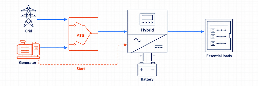
Para um ATS do lado de entrada da concessionária/gerador, calcule a corrente do gerador a partir da sua classificação em kVA e compare com a corrente máxima de entrada AC aceita pelo inversor. Suponha um gerador monofásico de 15 kVA, 230 V, que alimenta um carregador de inversor. Sua corrente nominal é cerca de 65,2 A. Se o inversor aceita apenas 50 A, suas configurações ou proteção a montante podem limitar a corrente de carga e passagem, mas o circuito fonte do ATS ainda deve ser coordenado com o disjuntor do gerador, condutores e caminho real da carga. Não assuma que o limite de entrada do software substitui a proteção do circuito.
A operação do gerador adiciona requisitos de controle que diagramas apenas solares não mostram: sinal de partida, tentativas de partida, atraso de aquecimento, verificação de disponibilidade da fonte, tempo mínimo de funcionamento, resfriamento, cronograma de exercício, feedback de baixo combustível ou falha, e limites de estado de carga da bateria. Um ATS básico de detecção de tensão pode transferir cargas, mas pode não coordenar a potência de carga ou impedir que o carregador do inversor sobrecarregue um pequeno gerador. Onde o inversor híbrido gerencia o gerador, use os contatos secos especificados e a sequência de controle. Se o gerador iniciar, mas a carga não transferir, siga a sequência de diagnóstico de transferência do gerador ATS para localizar o primeiro controlador ou estado de caminho de energia ausente.
Sistemas de três fontes podem exigir duas etapas de transferência intertravadas ou equipamentos de manobra de múltiplas fontes projetados para esse fim. A IEC 60947-6-1:2026 observa limites em torno de TSE de múltiplas fontes e híbridas dentro de sua descrição de escopo, portanto, o conjunto completo e o arranjo do controlador devem ser verificados em vez de montados a partir de interruptores não relacionados e assumidos como conformes.
Conectado à Rede versus Fora da Rede: O que muda na sequência de transferência?
Sequência de Backup Híbrido Conectado à Rede
Em operação normal, a utilidade estabelece a referência da rede e pode fornecer cargas através do caminho de passagem do inversor. Quando a tensão ou frequência da rede sai da janela permitida, o dispositivo de isolamento aprovado abre a conexão com a utilidade. Somente após a confirmação do isolamento o inversor formador de rede pode energizar o barramento de backup. Quando a utilidade retorna e permanece estável pelo atraso configurado, o sistema resincroniza ou realiza uma transição aberta de acordo com sua lógica de controle aprovada.
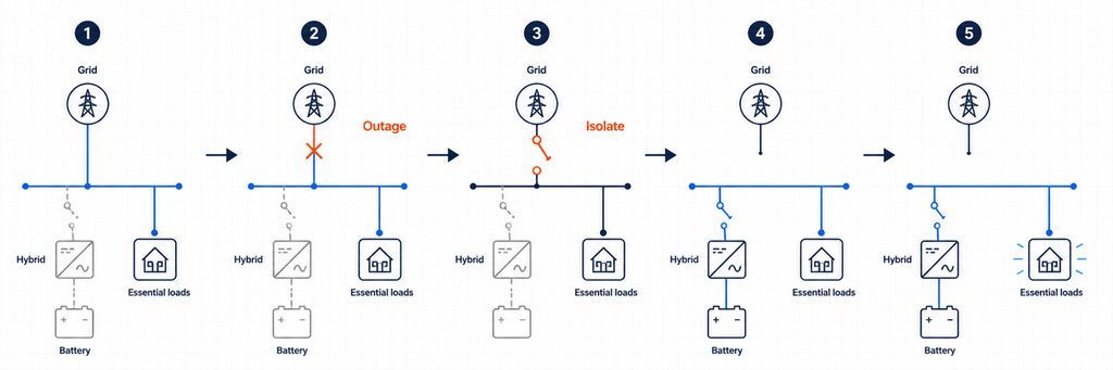
Um ATS genérico que apenas detecta “sem tensão” pode não saber se o inversor completou a isolação, se seu barramento de backup está estável ou se a reconexão é permitida. É por isso que sistemas híbridos frequentemente dependem de um controlador integrado, uma interface de backup dedicada ou coordenação de contato seco especificada pelo fabricante do inversor.
Sequência de Seleção de Fonte Off-Grid
Em uma instalação off-grid, o inversor é normalmente a fonte formadora da rede. A entrada alternativa da utilidade ou do gerador torna-se aceitável apenas após sua tensão e frequência estabilizarem. Um ATS do lado da entrada pode escolher entre a utilidade e o gerador antes de alimentar o inversor/carregador. O relé interno do inversor então decide se deve passar a fonte aceita ou continuar suportando as cargas com energia da bateria.
Se um segundo ATS do lado de saída fornecer desvio de manutenção, sua lógica deve ser coordenada com o inversor. O projeto deve evitar que uma fonte de desvio seja conectada a uma saída de inversor energizada, a menos que o equipamento seja especificamente destinado à operação paralela sincronizada. O intertravamento mecânico e elétrico não deve depender apenas de comandos de software.
Polos, Comutação Neutra e Aterramento
Não escolha 2P, 3P ou 4P apenas com base em uma simples regra de “fase única versus três fases”. Determine se o neutro deve permanecer solidamente conectado ou ser comutado, como cada fonte é aterrada, onde existe a ligação neutro-terra e como a proteção contra corrente residual se comporta em cada estado da fonte.
Um sistema de linha e neutro monofásico pode usar um arranjo de transferência de dois polos onde ambos os condutores devem ser comutados. Um sistema trifásico de quatro fios pode exigir um ATS de quatro polos quando a fonte alternativa cria um neutro derivado separadamente ou referenciado de forma diferente. Outros sistemas mantêm deliberadamente um neutro comum. O arranjo correto depende do projeto do inversor, do código local, dos requisitos da utilidade e do diagrama aprovado pelo fabricante.
O manuseio incorreto do neutro pode criar caminhos paralelos de neutro, corrente circulante, proteção contra corrente residual ineficaz, disparo indesejado ou um sistema de backup flutuante. Faça uma tabela de estado neutro e terra para modo de utilidade, modo de ilha, modo de gerador e desvio de manutenção. Se a tabela não mostrar uma estratégia de ligação intencional em cada estado, o projeto não está pronto para instalação.
A Capacidade de Curto-Circuito Não é a Mesma que a Corrente Contínua
Sistemas híbridos têm duas fontes de corrente de falha muito diferentes. A utilidade pode fornecer uma alta corrente de curto-circuito prospectiva. Um inversor normalmente limita a saída eletronicamente e pode fornecer apenas um múltiplo modesto da corrente nominal por uma curta duração. O ATS ainda precisa suportar e, onde necessário, fechar sobre o pior dever de falha disponível em seu ponto instalado.
Verifique a corrente de falta disponível de cada fonte conectada, do dispositivo de proteção a montante e dos dados condicionais de curto-circuito ou de resistência e fechamento do fabricante do ATS. Não assuma que a corrente de falta limitada de um inversor torna um pequeno interruptor de transferência aceitável se os mesmos contatos estiverem conectados a um desvio de utilidade forte.
Para projetos orientados pela IEC, IEC 60947-6-1:2026 cobre equipamentos de comutação de transferência usados para transferir uma carga entre fontes. Para projetos na América do Norte, a visão geral da certificação de interruptores da UL identifica as categorias UL 1008 para interruptores de transferência automáticos e não automáticos. Sempre aplique a edição e as regras de instalação adotadas pela autoridade competente do projeto.
Tempo de Transferência: Um ATS Não É Automaticamente um UPS
Uma transferência de ATS inclui detecção, validação, operação mecânica e tempo de estabilização. Mesmo um interruptor rápido pode criar uma interrupção longa o suficiente para redefinir controles, contatores, equipamentos de comunicação ou computadores. Um inversor híbrido com um relé de transferência interno pode suportar uma transição mais curta do que um ATS eletromecânico separado, mas o valor real deve vir da documentação e dos testes do sistema.
Classifique as cargas pela tolerância a interrupções. Iluminação e refrigeração podem tolerar uma breve interrupção. Servidores, CLPs, equipamentos médicos e dispositivos de rede podem exigir um UPS ou um caminho de inversor sem interrupção. Não prometa “energia ininterrupta” com base na classificação de corrente do ATS.
Detalhes de Controle e Sensoriamento que Determinam se Funciona
- Detecção de fonte: Meça a tensão e a frequência nos terminais da fonte real. A produção de PV ou o estado de carga da bateria não é o mesmo que uma fonte de backup AC saudável.
- Atrasos de transferência: Evite ciclos rápidos durante condições instáveis da rede e permita que um gerador ou barramento do inversor se estabilize.
- Fonte preferencial: Decida se a saída de backup do inversor, o desvio da rede ou o gerador é a fonte normal para cada ATS.
- Contatos secos: Confirme as classificações de contato sem tensão, polaridade lógica e comportamento de segurança antes de conectar os controles do inversor ou do gerador.
- Lógica de retorno: Defina se o sistema retorna automaticamente à rede, aguarda a recuperação da bateria ou requer aprovação manual.
- Modo de falha: Decida o que acontece se o controlador do inversor, o motor do ATS, o fusível de detecção ou o link de comunicação falharem.
Para projetos que necessitam de status remoto, selecione um interruptor de transferência automática com os contatos auxiliares ou opções de comunicação necessárias. Mantenha o intertravamento da fonte cabeada independente da supervisão.
Como Ler Folhas de Dados do Inversor e do ATS Juntas
O manual do inversor e a folha de dados do ATS usam termos diferentes, então crie uma verificação cruzada em vez de comparar uma linha de “corrente nominal”.
| Dados do inversor | Dados do ATS para comparar | Pergunta de design |
|---|---|---|
| Corrente de backup contínua máxima | Corrente operacional nominal e categoria de utilização | Os contatos podem suportar a saída do inversor continuamente? |
| Corrente máxima de entrada/passagem AC | Corrente operacional nominal e capacidade do terminal | O ATS pode suportar o caminho maior da rede ou do gerador? |
| Curva de sobrecarga de saída | Dever de fazer/quebrar e categoria de carga | Eventos de motor ou transformador causarão estresse de transferência ou desligamento do inversor? |
| Janelas de tensão/frequência da rede e de backup | Faixa de detecção do controlador e limites ajustáveis | Ambos os dispositivos concordarão que uma fonte é aceitável? |
| Tempo de transferência interno | Tempo de operação e atraso intencional do ATS | Que interrupção a carga realmente experimentará? |
| Diagrama de neutro/aterramento | Arranjo de comutação 2P, 3P ou 4P | Cada estado de operação preserva o sistema de ligação aprovado? |
| Contribuição máxima de falha | Classificação de resistência a curto-circuito/classificação condicional | O interruptor está coordenado para fontes de inversor e da rede? |
| Interface de contato seco ou de comunicação | Entradas, saídas e contatos auxiliares do controlador | Os dispositivos podem trocar status permissivo, de falha e de posição com segurança? |
Se um valor estiver faltando, solicite-o antes de emitir a especificação do interruptor. “Compatível com solar” não é uma classificação elétrica. Da mesma forma, “ATS de 63 A” não indica se o dispositivo é adequado para a tensão, categoria de carga, nível de falha, sequência de comutação ou certificação de mercado.
Erros Comuns de Dimensionamento de ATS para Inversores Híbridos
Dimensionamento a partir de kW do Array de PV
Um array de 12 kWp não significa que o ATS suporte 12 kW. A classificação AC do inversor, o limite de descarga da bateria, o caminho de passagem da rede e a demanda de carga transferida determinam a corrente em diferentes locais.
Usando Apenas a Classificação de Saída do Inversor
A rede ou gerador pode passar mais corrente através de um ATS do que o inversor pode produzir. Esta é a razão mais importante para registrar as classificações de passagem e desvio separadamente.
Duplicando uma Função de Transferência Interna
Dois controladores automáticos podem emitir comandos contraditórios, criar interrupções desnecessárias ou contornar a sequência de isolamento aprovada do inversor. Use um relacionamento de controle mestre documentado.
Assumindo que Qualquer Inversor Conectado à Rede Pode Fornecer Backup
O Departamento de Energia dos EUA explica que inversores que seguem a rede desligam quando a energia da rede não está disponível, enquanto a capacidade de formação de rede é necessária para operação fora da rede ou de backup. Um ATS sozinho não fornece essa capacidade.
Ignorando o Comportamento do Neutro
Uma classificação de corrente pode estar correta enquanto o sistema permanece inseguro devido a uma configuração incorreta de neutro ou aterramento. Revise a operação do condutor de proteção e da corrente residual em cada estado de transferência.
Tratando o ATS como Proteção contra Sobrecorrente
Um interruptor de transferência muda os caminhos de fonte. A menos que o produto selecionado seja especificamente um arranjo de proteção da classe CB, disjuntores ou fusíveis coordenados ainda são necessários.
Testes de Comissionamento Antes que o Sistema Entre em Operação
- Verifique a identidade do condutor, torque dos terminais, sequência de fases, polaridade, continuidade do neutro e conexões de aterramento de proteção.
- Confirme que os nomes das fontes do ATS correspondem às fontes preferenciais e alternativas reais.
- Meça a tensão e a frequência da rede, do backup do inversor e do gerador nos pontos de detecção.
- Simule uma falha na rede e confirme que o isolamento da utilidade ocorre antes que o barramento da ilha seja energizado.
- Aplique cargas essenciais representativas e verifique se a corrente de backup permanece dentro do limite do inversor.
- Desative ou falhe o inversor e verifique a resposta de desvio pretendida sem retroalimentar sua saída.
- Restaure a utilidade e confirme o atraso de retransferência, verificações de estabilidade da fonte e estado operacional final.
- Teste estados de bateria baixa, sobrecarga, parada de emergência, operação manual e perda de comunicação.
- Registre os tempos de transferência, correntes, alarmes, configurações do controlador e alterações na fiação conforme construído.
O comissionamento deve ser realizado por pessoal qualificado usando um procedimento de teste aprovado. Sistemas solares e de bateria conectados à utilidade podem energizar condutores de múltiplas direções mesmo quando um desconector está aberto.
Lista de Verificação de Especificação do ATS para um Projeto Solar Híbrido
| Item de especificação | Entrada do projeto |
|---|---|
| Função e localização do ATS | Seletor de fonte de entrada, desvio de saída de backup ou isolamento de serviço |
| Fonte I / Fonte II | Utilidade, gerador, saída de backup do inversor ou combinação aprovada |
| Corrente de projeto da carga transferida | A partir do cronograma de carga e regras locais |
| Corrente de backup do inversor | Valor máximo contínuo do fabricante |
| Corrente de passagem/desvio da rede | Máximo permitido no ponto instalado |
| Corrente operacional nominal | Selecionado após verificação de carga, desclassificação e coordenação |
| Tensão, frequência, fases | Correspondem a ambas as fontes e carga |
| Polos e neutro | Baseado no projeto de aterramento aprovado |
| Dados de duty de falha | Corrente de falha disponível e dispositivo de proteção coordenado |
| Método de transferência | Transição aberta, a menos que um método sincronizado aprovado seja necessário |
| Controle e feedback | Limiares de detecção, atrasos, contatos secos, status, comunicações |
| Evidência de compatibilidade | Diagrama unifilar aprovado para inversor e certificação aplicável |
Regra de Seleção Final
O tamanho correto do ATS para um inversor solar híbrido é a classificação necessária na fronteira elétrica real do interruptor—não o número impresso ao lado do array PV. Primeiro, prove que o sistema possui um método de formação de rede e isolamento aprovado. Em seguida, compare a corrente de carga transferida, a corrente de saída de backup do inversor e a corrente de passagem ou desvio da rede. Selecione a maior corrente credível através daquele local e finalize o projeto com verificações de polo, neutro, duty de falha, tempo de transferência, proteção e controlador.
Para uma seleção específica do projeto, envie à JUTRION o diagrama unifilar, tensão do sistema e fases, modelo do inversor, corrente de saída de backup, classificação de passagem, cronograma de carga transferida, corrente de falha disponível e sinais de controle necessários. Esses detalhes permitem que a configuração do ATS seja compatível com a arquitetura híbrida ou fora da rede real.
Perguntas Frequentes
Eu preciso de um ATS com um inversor solar híbrido?
Nem sempre. Muitos inversores híbridos já contêm um relé de transferência interno ou funcionam com uma interface de backup dedicada. Um ATS externo é apropriado apenas quando a arquitetura aprovada pelo fabricante exige funções como seleção de entrada entre rede e gerador, desvio da saída do inversor ou redundância de manutenção. Adicionar outro ATS sem verificar o diagrama aprovado pode criar uma lógica de transferência conflitante.
Um ATS pode fazer um inversor solar conectado à rede funcionar durante uma queda de energia?
Não. Um inversor convencional que segue a rede se desconecta quando a rede elétrica não está disponível. Um ATS não pode fornecer capacidade de formação de rede. A operação de backup requer equipamentos de ilhamento compatíveis, um inversor projetado para estabelecer um barramento AC local e, geralmente, armazenamento de bateria ou outra fonte de energia estável.
O tamanho do ATS deve corresponder à classificação em kW do inversor solar?
Não necessariamente. O ATS deve ser classificado para a corrente máxima que pode passar pela sua posição instalada. Um inversor híbrido pode fornecer 35 A em modo de backup enquanto permite 63 A de corrente de passagem pela rede. Se o ATS carregar esse caminho da rede, a corrente credível maior—não apenas a potência do array PV ou o kW do inversor—controla a classe de corrente inicial.
Como eu converto kVA de um inversor híbrido para corrente do ATS?
Para sistemas monofásicos, divida a potência aparente em VA pela tensão: I = S ÷ V. Para sistemas trifásicos balanceados, use I = S ÷ (√3 × V). Compare o resultado com a corrente AC máxima declarada do inversor, pois o limite da placa de identificação tem precedência sobre um cálculo ideal. Em seguida, verifique se a corrente de passagem pela rede ou a demanda de carga transferida é maior.
O ATS deve ser instalado antes ou depois do inversor híbrido?
Depende da função pretendida. Um ATS do lado de entrada pode selecionar a rede ou o gerador antes do inversor/carregador. Um ATS do lado de saída pode selecionar a saída de backup do inversor ou um desvio direto da rede para um painel de carga essencial. Um dispositivo de transferência de limite de serviço pode ser parte de uma interface de backup dedicada. Essas posições têm diferentes requisitos de corrente, neutro, detecção e controle.
Eu preciso de um ATS de 2 polos ou 4 polos para um inversor solar?
Escolha a disposição dos polos com base no número de fases e no projeto aprovado de neutro e aterramento. Alguns sistemas mantêm um neutro sólido; outros devem alternar o neutro para evitar caminhos paralelos ou acomodar uma fonte derivada separadamente. Não aplique uma regra universal de “fase única igual a 2P” ou “três fases igual a 4P” sem verificar o manual do inversor, o código local, a proteção contra corrente residual e o arranjo de aterramento.
Posso usar um ATS maior do que a corrente de saída do inversor?
Sim, desde que a tensão, os polos, o dever de utilização, a classificação de falha, a proteção, os controles e a certificação sejam adequados. Um ATS maior é comumente necessário quando a corrente de desvio da rede excede a corrente de backup do inversor. No entanto, o interruptor maior não aumenta a saída do inversor ou a capacidade da bateria; as cargas de backup ainda devem permanecer dentro do limite do inversor.
Um ATS é rápido o suficiente para substituir um UPS?
Não automaticamente. A detecção de fonte, validação, operação mecânica e estabilização do inversor podem criar uma interrupção. Computadores sensíveis, servidores, controles, equipamentos de comunicação ou cargas médicas ainda podem precisar de um UPS ou de um caminho de energia sem interrupção verificado. Verifique o tempo de transferência do sistema completo em vez de confiar na classificação de corrente do ATS.
Referências
- IEC 60947-6-1:2026 — Equipamento de Comutação de Transferência
- UL Solutions — Serviços de Certificação e Avaliação de Interruptores
- Departamento de Energia dos EUA — Integração Solar: Fundamentos de Inversores e Serviços de Rede
- Departamento de Energia dos EUA — Guia Solar e Orientações para Inversores Formadores de Rede
