

Быстрый ответ по подбору
Подбирайте солнечный автоматический выключатель постоянного тока по его фактическому положению на однолинейной схеме. Используйте скорректированное на холод напряжение стринга Vок для напряжения, ток модуля Iск умноженный на количество параллельных стрингов и требуемый проектом коэффициент для тока, затем подтвердите защиту кабеля, отключающую способность по постоянному току, схему подключения полюсов и снижение номинальных характеристик в корпусе. Выбирайте MCB или MCCB только после того, как эти параметры определены.
Одна и та же фотоэлектрическая батарея может требовать устройство на 20 А на одном стринге и устройство на 100 А на выходе сумматора. Оба устройства видят примерно одинаковое напряжение стринга, но они не пропускают одинаковый ток и не защищают один и тот же проводник. Поэтому запрос вида “солнечный выключатель 1000 В постоянного тока” ещё не готов к выбору модели.
Первый вопрос не в том, Какой номинал выключателя? А в том, Где находится выключатель и что может подать ток короткого замыкания в этой точке?
Разместите выключатель на карте защиты фотоэлектрической системы
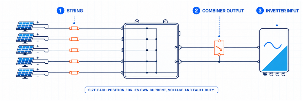
Карта защиты фотоэлектрической системы постоянного тока с указанием позиций выключателей на стринге, выходе сумматора и входе инвертораСолнечная батарея — это цепь электрически различных участков. Отметьте предполагаемый выключатель, прежде чем открывать каталог:
Фотоэлектрический стринг → вход стрингового сумматора → объединённый выход постоянного тока → вход постоянного тока инвертора
Перемещение на одну позицию вправо меняет путь тока. Модули, соединённые последовательно, повышают напряжение. Совместимые стринги, соединённые параллельно, повышают ток. Выключатель на отдельном входе обычно пропускает один стринг; выключатель на общем выходе пропускает все стринги, подключённые к этому выходу.
| Позиция | Ток через устройство | Основная задача, которую нужно определить | Обычный короткий список |
|---|---|---|---|
| Отдельный стринг | Один стринг | Защита от обратного тока и изоляция стринга | Предохранитель gPV или фотоэлектрический DC MCB, если это допускается проектом |
| Выход сумматора | Сумма параллельных стрингов | Защита объединённого фидера и выходного кабеля | Фотоэлектрический DC MCB, DC MCCB или разъединитель нагрузки с отдельной защитой |
| Вход постоянного тока инвертора | Ток, назначенный на этот вход инвертора или тракт MPPT | Изоляция оборудования и согласованная защита | Выключатель или разъединитель нагрузки, указанный в системном проекте |
В таблице намеренно сказано “короткий список”. Автоматический выключатель не обязателен в каждой позиции. Стринг может использовать предохранители gPV; инвертор может уже иметь подходящий DC-разъединитель; выходу может требоваться изоляция, а защита от сверхтоков обеспечивается в другом месте. Определите недостающую функцию, прежде чем выбирать устройство.
Статья о подборе солнечного сумматорного бокса объясняет, как группировка MPPT определяет, какие стринги могут использовать общий выход. Сначала завершите это архитектурное решение. Выключатель не может исправить стринги, которые вообще не следовало соединять параллельно.
Определите окно тока, а не только минимальный номинал в амперах
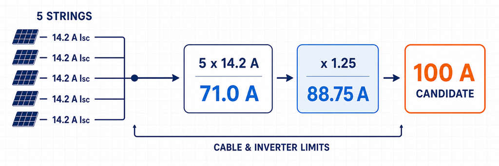
Подбор тока солнечного DC-выключателя от пяти параллельных стрингов до кандидата на 100 амперРасчёт тока имеет две стороны. Выключатель должен пропускать расчётный ток в установленных условиях, но он не должен быть настолько большим, чтобы защищаемый кабель или подключённое оборудование оказались вне своих пределов.
Для согласованных фотоэлектрических стрингов:
Isc,путь = Np × Isc,модуль
где:
- Isc,путь — базовое значение тока короткого замыкания для выбранного пути в амперах;
- Np — количество стрингов, соединённых параллельно на этом пути;
- Isc,модуль — ток короткого замыкания модуля при указанных условиях испытания.
Метод установки проекта затем определяет обработку расчётного тока:
Iрасч = Isc,путь × Kпроект
Kпроект — это не число для угадывания. Оно представляет собой текущий коэффициент, требуемый принятыми правилами монтажа и расчётными основаниями. В североамериканских примерах обычно указывается 1,25 или 1,56 в зависимости от номинала оборудования и пути расчёта. В проектах, ориентированных на IEC, необходимо использовать применимые требования к монтажу, данные модуля и инструкции производителя, а не переименовывать одну из этих цифр в универсальный “множитель IEC”.”
Полезное окно выбора:
Требуемый длительный ток ≤ используемый номинал или уставка автоматического выключателя ≤ допустимый предел защищаемой цепи
Верхняя граница может быть задана сниженной допустимой токовой нагрузкой кабеля, номиналом клемм, входным пределом инвертора или другим защищаемым компонентом. Выбор следующего стандартного автоматического выключателя выше Iрасч допустим только тогда, когда верхняя граница по-прежнему выполняется.
Последовательные модули не умножают ток автоматического выключателя
Двадцать модулей, соединённых последовательно, не дают двадцатикратный ток модуля. Они увеличивают напряжение цепочки, тогда как ток цепочки остаётся основанным на одном модуле. Пять одинаковых цепочек, соединённых параллельно, дают примерно пятикратный ток. Именно поэтому деление мощности массива на предполагаемое постоянное напряжение является плохой заменой паспортным данным модуля и схеме соединения цепочек.
Используйте Iск и Iмп для разных проверок
Iск — это исходная точка тока короткого замыкания, используемая при проектировании защиты от сверхтоков в фотоэлектрических системах. Iмп описывает рабочий ток вблизи максимальной мощности и помогает проверить нагрузку MPPT инвертора и нормальный режим работы. Держите оба значения в рабочей таблице. Не заменяйте основу защиты более низким Iмп, и не забывайте о пределе рабочего тока инвертора после расчёта на основе Iск.
Держите примеры IEC и североамериканские примеры в своих рамках
Eaton’s North American PV application guide, for example, distinguishes 80%-rated and 100%-rated molded-case breakers. Its worked method uses 1.56 × Iск для автоматического выключателя с номиналом 80% и 1,25 × Iск для автоматического выключателя с номиналом 100% вместе с проверками проводника и температуры. Эти цифры полезны внутри контекста NEC/UL и конкретного изделия. Их не следует отрывать от этого контекста и публиковать как глобальное правило для фотоэлектрических систем.
Для проекта по IEC начните с редакции, принятой договором или юрисдикцией. Публичная область применения IEC 60364-7-712 подтверждает, что она касается электрических установок фотоэлектрических систем, но страница области применения не устанавливает полный расчёт для конкретного проекта. Запишите фактическое расчётное правило рядом с Kпроект; это сохраняет арифметику проверяемой и не позволяет поставщику незаметно сменить метод.
Устанавливайте номинал напряжения по холодному Vок и схеме полюсов
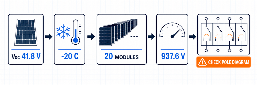
Расчёт напряжения фотоэлектрической цепочки в холодную погоду и проверка конфигурации полюсов автоматического выключателя постоянного токаНапряжение цепочки максимально, когда модули находятся в режиме холостого хода и холодные. Автоматический выключатель, выбранный только по STC Vок модуля, может оказаться заниженным холодным утром.
Если модуль предоставляет отрицательный температурный коэффициент Vок в процентах на градус Цельсия, предварительный расчёт выглядит так:
Vок,холод,модуль = Voc,STC × [1 + |βVoc| × (25 − Tмин)]
Vок,холод,строка = Ns × Вок,холод,модуль
где Ns — количество модулей, соединённых последовательно, а Tмин — минимальная расчётная температура проекта. Вводите −0,27%/°C как 0,0027. Если производитель модуля или принятый метод проектирования задаёт другой расчёт температуры, используйте его последовательно для инвертора и каждого компонента постоянного тока.
Заявленное напряжение постоянного тока автоматического выключателя должно быть не менее утверждённого максимального напряжения цепи. Он также должен достигать этого номинала при точной схеме расположения полюсов, указанной изготовителем. В некоторых высоковольтных выключателях постоянного тока несколько контактов соединены последовательно для распределения гашения дуги. Четырёхполюсный корпус не означает автоматически выключатель на 1000 В или 1500 В.
Перед заказом подтвердите:
- номинальное рабочее напряжение постоянного тока для конкретной модели;
- число полюсов, используемых последовательно при этом напряжении;
- допустимый путь положительного и отрицательного проводника;
- чувствительность к полярности и направление «линия/нагрузка»;
- заявленную пригодность для разъединения, если такая функция требуется.
Существующий калькулятор напряжения холодной цепочки JUTRION может дать предварительный результат Vок,холод,строка Он был создан для проверки напряжения УЗИП фотоэлектрических систем, но напряжение холодной цепочки также используется при проверках выключателей, разъединителей, кабелей и инверторов.
Используйте путь тока короткого замыкания, чтобы решить, может ли выключатель защитить цепь
Номинальный ток выключателя и его отключающая способность отвечают на разные вопросы:
- Номинальный ток или уставка срабатывания: может ли устройство проводить нормальный ток и защищать цепь от применимой перегрузки по току?
- Отключающая способность по постоянному току: can it safely interrupt the prospective fault current at the stated DC voltage and wiring condition?
Do not compare a 100 A breaker rating with a 50 A reverse-current contribution and conclude that the device can interrupt the fault. A normal-current label does not prove trip response, conductor protection or DC interruption performance.
At a string fault, healthy parallel strings may feed reverse current into the damaged string. An initial screen is:
Iобратный, оценка = (Np − 1) × Iкз, цепочка
This shows why reverse-current exposure grows as more strings are paralleled. It does not by itself select a breaker or fuse. The final design must consider the module’s maximum series-fuse rating, conductor capacity, protective-device characteristic and the requirements of the adopted installation rules.
At a combined output, identify every source that can feed the fault. PV modules are current-limited compared with a utility or battery, but parallel sub-arrays, connected power-conversion equipment and any storage interface can change the available current. If batteries are connected at DC level, stop treating the circuit as a PV-only example; battery fault-current assessment deserves its own design.
Do Not Assume a Large Breaking Number Solves a Poor Trip Decision
A breaker may have ample ultimate interruption capacity and still fail to protect the intended conductor because its trip threshold or time-current response is unsuitable. Conversely, a low-current breaker can have a normal rating close to the load yet lack the required DC breaking capacity at the actual voltage. Verify both the interruption rating and the protective characteristic.
PV faults can also occur near the lower end of a breaker’s operating range. Selectivity between string devices and an output breaker is not guaranteed simply because the output device has the larger ampere label. Use manufacturer coordination data where selective operation matters, and treat the claimed trip curve as model-specific evidence rather than a generic “C-curve for solar” rule.
IEC 60947-2:2024 applies to circuit breakers for instructed or skilled persons with rated voltages up to 1000 V AC or 1500 V DC. That product-standard scope supports the key procurement rule: obtain verified DC ratings for the exact breaker, not an AC breaking figure or a family-level marketing label.
Choose DC MCB or DC MCCB After the Duty Is Visible
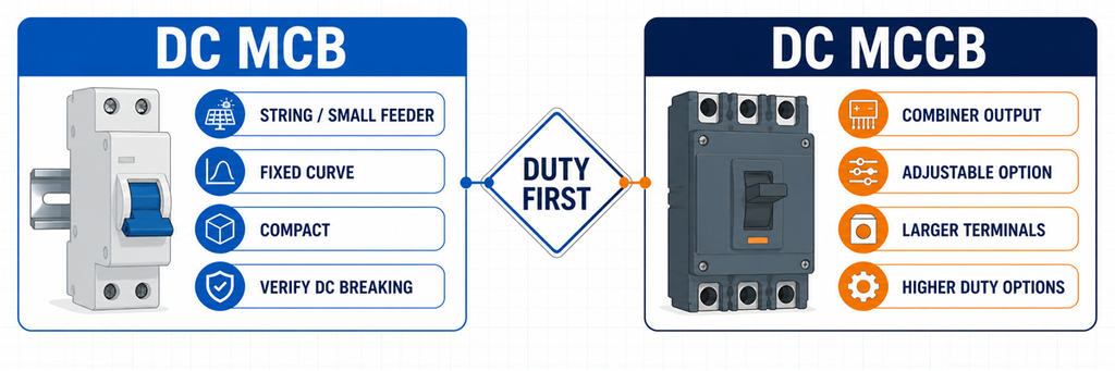
DC MCB versus DC MCCB comparison for solar string and combiner output protection“Use an MCB below 63 A and an MCCB above 63 A” is convenient, but it is not a universal engineering boundary. Product ranges overlap. Some DC MCB families extend above 63 A; some projects choose an MCCB at a lower current because they need a different breaking capacity, adjustable protection, larger terminals or accessories.
| Project need | DC MCB is the stronger shortlist when… | DC MCCB is the stronger shortlist when… |
|---|---|---|
| Installation format | A compact DIN-rail device fits the string or small feeder | A molded-case panel device, larger conductors or busbars are involved |
| Protection adjustment | The declared fixed characteristic suits the circuit | An available adjustable trip unit helps coordinate the feeder |
| Breaking duty | The model’s verified DC breaking capacity exceeds the fault level | The circuit requires a higher verified DC interruption duty |
| Control and indication | Basic handle position or modular auxiliary options are sufficient | Shunt trip, auxiliary contacts or remote operation are required and supported |
| Typical PV position | Individual string or lower-current branch | Combiner output or higher-current array feeder |
The decision is not about which family is “better.” It is about which verified product satisfies the location’s current window, voltage/pole arrangement, interruption duty, cable interface and control requirements. After those values are known, compare the available JUTRION DC MCB configurations and JUTRION DC MCCB configurations.
Decide Whether the Location Needs a Fuse, Breaker or Isolator
Three devices often appear in the same combiner box, but their jobs are not interchangeable.
- gPV fuse and holder: provides PV string or array overcurrent protection within its verified duty. It does not provide maintenance isolation unless the complete fuse-switch arrangement is designed for that function.
- автоматический выключатель постоянного тока: provides automatic overcurrent operation plus switching within its declared ratings. It does not automatically satisfy a required isolating function unless it is declared suitable for isolation.
- DC switch-disconnector: provides manual load switching and isolation within its utilization rating. It does not provide automatic overload or short-circuit protection.
At string level, gPV fuses are common because parallel strings can feed reverse current into a faulted string and the module provides a maximum series-fuse rating. A resettable breaker may be useful where its PV duty and characteristic are verified, but “resettable” is not evidence that it coordinates better.
At a combiner output, a breaker may protect the combined cable and provide switching. Another design may use a switch-disconnector because overcurrent protection is located elsewhere. State which function the device performs; otherwise two suppliers can quote different architectures under the same “DC breaker” request.
Coordinate the Breaker with the Complete DC Path
A correct breaker can still be wrong in an incorrectly coordinated system. Complete five checks before freezing the model.
Cable
Verify conductor ampacity after ambient-temperature, grouping, installation and termination corrections. The breaker rating or setting must remain within the permitted protection relationship. Do not increase the breaker solely to stop nuisance trips without reviewing the enclosure temperature and cable.
Inverter
Compare cold string voltage with maximum DC input voltage. Compare the parallel-string operating current with the MPPT/input-current limit, and total Iск with the inverter’s permitted short-circuit current. The breaker does not authorize an array that exceeds the inverter data.
String fuses
Confirm whether each string needs reverse-current protection and whether the selected fuse/link remains below the module maximum series-fuse rating while carrying the required current under enclosure conditions. The common output breaker and string fuses normally protect different conductors.
УЗИП постоянного тока для ФЭ
An SPD limits transient overvoltage; it is not the normal overcurrent device. Follow the SPD manufacturer’s backup-protection instructions and check its short-circuit behavior. The guide to selecting a DC SPD for solar PV covers UCPV, Type 2/Type 1+2 and protection-level decisions.
Enclosure and assembly
Outdoor combiner boxes can run substantially hotter than the surrounding air. Use the breaker’s actual temperature/altitude data, terminal limits and mounting instructions. Closely spaced protective devices, solar heating, cable losses and restricted airflow all affect usable current. Review the complete PV combiner-box assembly, not only the breaker nameplate.
If a catalogue curve shows that the breaker carries less current at the expected internal temperature, apply that curve before choosing the frame. If no applicable curve or assembly data is available, increasing the breaker rating by an improvised percentage is not a defensible thermal design. The larger breaker may also require a larger conductor, terminal or enclosure and may no longer protect the original cable.
IEC 62548-1:2023 covers PV array design requirements including DC wiring, electrical protection devices, switching and earthing provisions. IEC 60364-7-712:2025 applies to electrical installations of PV systems. These installation contexts are distinct from the circuit-breaker product standard.
One Array, Three Different Breaker Decisions
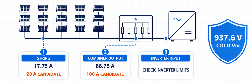
Solar DC breaker sizing example comparing string, combiner output and inverter input decisionsIllustrative design: each string has 20 identical modules. Module data states Voc,STC = 41.8 V, Iск = 14.2 A and βVoc = −0.27%/°C. The minimum design temperature is −20°C. Five compatible strings feed one inverter input through a combiner. For this example only, the project’s preliminary current method uses 1.25 × Iск.
First, establish the common voltage duty
Cold module Vок = 41.8 × [1 + 0.0027 × (25 − (−20))] = 46.88 V
Cold string Vок = 20 × 46.88 = 937.6 V
The strings are in parallel at the combiner, so their voltages do not add. The string device and the output device both require a verified voltage/pole arrangement above the approved maximum circuit voltage. A 1000 V DC class is the initial shortlist, subject to the project’s additional voltage treatment and the exact breaker diagram.
Position 1: one string
Preliminary string design current = 14.2 × 1.25 = 17.75 A
A 20 A PV-rated protective device is the first current candidate. Before choosing a DC MCB, compare this result with the module maximum series-fuse rating, conductor ampacity, required reverse-current protection and the exact trip characteristic. A gPV fuse may remain the better string-protection choice.
With five strings in parallel, the four healthy strings produce an initial reverse-current screen of:
(5 − 1) × 14.2 = 56.8 A
That figure explains why string protection deserves attention. It does not mean a 56.8 A string breaker should be fitted.
Position 2: combiner output
Total Iск = 5 × 14.2 = 71.0 A
Preliminary output design current = 71.0 × 1.25 = 88.75 A
A 100 A-class DC breaker is a current shortlist for the combined output. The handoff from MCB to MCCB now depends on the available product range, verified DC breaking capacity, required settings, terminal size and enclosure temperature—not on a universal 63 A rule.
Position 3: inverter input
The current arithmetic may be identical to the combiner output because it is the same feeder. The decision is not automatically identical. Confirm whether the inverter already provides a DC switch, whether an external breaker is required, the maximum input current and Iск, the permitted switching arrangement and the location needed for safe maintenance.
| Позиция | Calculated current starting point | Initial device direction | Decision that remains |
|---|---|---|---|
| Один стринг | 17.75 A | 20 A PV protective device candidate | gPV fuse or DC MCB; module/cable coordination |
| Выход сумматора | 88.75 A | 100 A-class DC breaker candidate | MCB/MCCB, DC breaking capacity, settings and temperature |
| Inverter input | Same feeder current | Breaker or switch-disconnector as required | Inverter limits and whether protection already exists |
The calculation has produced three different functional decisions from one array. That is more useful than quoting one breaker size for “a 100 kW solar system.”
Read the Breaker Datasheet as a Connected Rating Set
Do not approve the device by circling one number. Read these ratings together:
- Ue: rated operational voltage for the stated DC pole arrangement;
- In or frame/setting: current rating and available adjustment under reference conditions;
- Отключающая способность по постоянному току: declared interruption performance at the relevant DC voltage;
- trip characteristic: how and when the device operates, not simply a B/C/D letter borrowed from another family;
- isolation declaration: whether it can serve the required isolating function;
- pole and polarity diagram: the only valid connection for the declared high-voltage rating;
- temperature and altitude data: the basis for usable current in the real enclosure;
- terminals: conductor range, material, preparation and tightening torque;
- accessories: auxiliary contacts, shunt trip or remote operation where the system needs them.
A label such as “4P, 1000 V DC, 100 A” does not disclose the complete connected rating set. Ask for the exact technical sheet and wiring diagram for the ordered model.
Three Datasheet Warning Signs
- One breaking-capacity number with no DC voltage: interruption performance must refer to a stated voltage and test arrangement.
- A 1000 V claim with no pole diagram: the buyer cannot confirm how the arc chambers share voltage or where the conductors connect.
- One current rating with no reference temperature: the rooftop enclosure duty remains unknown.
These omissions do not automatically prove that a product is unsuitable, but they prevent an engineering selection. Resolve them before the device is installed in a live PV string.
Часто задаваемые вопросы
Какой размер автоматического выключателя постоянного тока мне нужен для солнечных панелей?
Use module Iск and the number of parallel strings on the protected path, then apply the current method required by the project. Select the next suitable rating only if it also protects the derated cable and stays within inverter and terminal limits. Check cold Vок, DC breaking capacity and pole wiring separately.
Можно ли использовать автоматический выключатель переменного тока на стороне постоянного тока солнечной системы?
Только если производитель явно заявляет точное устройство, напряжение постоянного тока, отключающую способность и расположение полюсов для данного применения с постоянным током. Одного номинала переменного тока недостаточно, поскольку устойчивую дугу постоянного тока труднее прервать.
Следует ли в фотоэлектрической цепочке использовать предохранитель или автоматический выключатель?
Предохранители gPV обычно используются для защиты отдельных цепочек от обратного тока. Автоматический выключатель постоянного тока с номиналом PV может быть выбран, если его характеристика, напряжение, отключающая способность и координация с кабелем/модулем подходят. Ответ зависит от схемы защиты, а не от предпочтения устройств с возможностью повторного включения.
Когда следует выбирать DC MCCB вместо DC MCB?
Автоматический выключатель постоянного тока (DC MCB)?
Выбирайте исходя из задачи. MCCB становится более предпочтительным вариантом, когда на выходе требуется более крупный корпус, более высокая подтверждённая отключающая способность, регулируемая защита, более крупные клеммы или дополнительные аксессуары управления. Не полагайтесь на универсальную границу в 63 А.
Нужен ли мне двухполюсный или четырехполюсный автомат для цепочки фотоэлектрических модулей на 1000 В?
Производитель выключателя определяет это по проверенной схеме полюсов постоянного тока для данной модели. Некоторые изделия требуют нескольких последовательных полюсов для достижения 1000 В; другие используют иную конструкцию. Следуйте точной схеме и маркировке полярности, а не выбирайте только по количеству полюсов.
Complete the Selection at Each Position
For an individual string, resolve reverse-current protection and the module’s series-protection limit. At the combiner output, resolve combined current, cable protection and DC breaking duty. At the inverter input, resolve the equipment limits and the required isolation point.
Only then choose the product family. A compact MCB постоянного тока may fit the string or smaller feeder; a MCCB постоянного тока may better fit the combined output. The final model is the one whose current, voltage, interruption, poles and installed-condition ratings all refer to the same circuit—not five individually impressive numbers collected from different conditions.
