

迅速なサイジング回答
太陽光DC回路ブレーカーは、単線結線図上の実際の設置位置でサイジングします。電圧には低温補正後のストリングVoc を使用し、電流にはモジュールIsc に並列ストリング数とプロジェクトの要求係数を掛けた値を使用し、その後ケーブル保護、DC遮断容量、極配線、筐体のディレーティングを確認します。これらの責務が判明してからMCBまたはMCCBを選択してください。.
同じPVアレイでも、あるストリングでは20 Aのデバイスが必要で、コンバイナ出力では100 Aのデバイスが必要になる場合があります。両方のデバイスが見るストリング電圧はほぼ同じですが、流れる電流も保護する導体も同じではありません。そのため「1000 V DCソーラーブレーカー」のような依頼は、モデル選定の準備ができていないのです。.
最初の質問は 「ブレーカーのサイズは?」 ではありません。 「ブレーカーはどこにあり、その地点の故障には何が電流を供給できるのか?」です。
PV保護マップ上にブレーカーを配置する
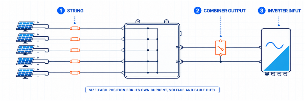
ストリング、コンバイナ出力、インバータ入力のブレーカー位置を示す太陽光PV DC保護マップ太陽光アレイは電気的に異なる回路の連鎖です。カタログを開く前に、提案するブレーカーをマークしてください:
PVストリング → ストリングコンバイナ入力 → 結合DC出力 → インバータDC入力
Moving one position to the right changes the current path. Modules in series raise voltage. Compatible strings in parallel raise current. A breaker at an individual input normally carries one string; a breaker at the common output carries all strings connected to that output.
| 位置 | デバイスを流れる電流 | 確立すべき主な責務 | 通常の候補リスト |
|---|---|---|---|
| 個別ストリング | One string | 逆電流保護とストリング隔離 | 設計上許容される場合はgPVヒューズまたはPV定格DC MCB |
| コンバイナ出力 | 並列ストリングの合計 | 結合フィーダおよび出力ケーブル保護 | PV定格DC MCB、DC MCCB、または個別保護付きスイッチ断路器 |
| インバータDC入力 | そのインバータ入力またはMPPT経路に割り当てられた電流 | 機器隔離と協調保護 | システム設計で指定されたブレーカーまたはスイッチ断路器 |
この表は意図的に「候補リスト」としています。回路ブレーカーがすべての位置で自動的に必要なわけではありません。ストリングにはgPVヒューズを使用する場合があり、インバータには適切なDCアイソレータが既に含まれている場合があり、出力には隔離が必要でも過電流保護は別の場所で提供される場合があります。デバイスを選択する前に、不足している機能を明確にしてください。.
の記事 太陽光コンバイナボックスのサイジング では、MPPTグルーピングがどのストリングが出力を共有できるかを決定する方法を説明しています。まずそのアーキテクチャの決定を完了してください。ブレーカーは、本来並列にすべきでなかったストリングを修正することはできません。.
最小アンペア定格だけでなく電流ウィンドウを確立する
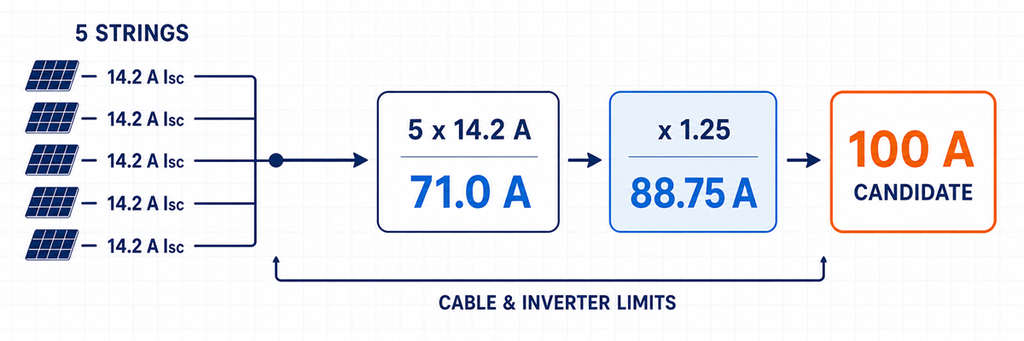
5つの並列ストリングから100アンペア候補までの太陽光DC回路ブレーカー電流サイジング電流計算には2つの側面があります。ブレーカーは設置条件下で設計電流を流せなければなりませんが、保護対象のケーブルや接続機器が限界を超えるほど大きくてもいけません。.
整合したPVストリングの場合:
Isc,path = Np × Isc,module
ここで:
- Isc,path は選択した経路の短絡電流基準(アンペア)です;;
- Np はその経路で並列接続されたストリング数です;;
- Isc,module は規定の試験条件におけるモジュール短絡電流です。.
プロジェクトの設置方法により、設計電流の扱いが決まります:
Iデザイン = Isc,path × Kプロジェクト
Kプロジェクト は推測する数値ではありません。採用される設置規則と設計基準によって要求される電流係数を表します。北米の例では、機器定格と計算経路に応じて1.25または1.56が一般的に示されます。IEC指向のプロジェクトでは、これらの数値の1つを普遍的な「IEC乗数」として再ラベル付けするのではなく、適用される設置要件、モジュールデータ、および製造元の指示を使用する必要があります。“
有用な選択ウィンドウは次のとおりです。
必要な通電電流 ≤ 使用可能なブレーカー定格または設定 ≤ 許容される保護回路限界
上限は、ディレーティングされたケーブル許容電流、端子定格、インバーター入力制限、または別の保護対象コンポーネントによって設定される場合があります。Iデザイン を超える次の標準ブレーカーを選択することは、上限が依然として満たされる場合にのみ有効です。.
直列モジュールはブレーカー電流を倍増させません
20個のモジュールを直列にしても、モジュール電流の20倍にはなりません。ストリング電圧は上昇しますが、ストリング電流は1つのモジュールに基づいたままです。5つの同一ストリングを並列にすると、電流は約5倍になります。これが、想定DC電圧でアレイのワット数を割ることが、モジュールのデータシートとストリング計画の代わりとして不十分な理由です。.
Isc とImp を異なるチェックに使用する
Isc は、PV過電流設計で使用される短絡電流の出発点です。Imp は最大電力付近の動作電流を表し、インバーターのMPPT負荷と通常動作の確認に役立ちます。ワークシートには両方の値を保持してください。保護基準を低い方のImp, に置き換えず、Isc.
から計算した後にインバーターの動作電流制限を忘れないでください。
Eaton’s North American PV application guide, for example, distinguishes 80%-rated and 100%-rated molded-case breakers. Its worked method uses 1.56 × Isc 例えば、Eatonの北米PVアプリケーションガイドでは、80%定格と100%定格のモールドケースブレーカーを区別しています。その計算方法では、80%定格ブレーカーには1.56 × Isc を使用し、100%定格ブレーカーには1.25 × I.
を導体および温度チェックとともに使用します。これらの数値は、そのNEC/ULおよび製品コンテキスト内で有用です。それらを切り離して世界的なPV規則として公開すべきではありません。プロジェクト; IECプロジェクトの場合は、契約または管轄区域で採用された版から始めます。IEC 60364-7-712の公開範囲は、PV電気設備を扱っていることを確認していますが、範囲ページは特定のプロジェクトの完全な計算を確立するものではありません。実際の設計規則をK.
の横に記録してください。これにより計算のレビューが可能になり、サプライヤーが方法を黙って切り替えるのを防ぎます。oc 低温時のV
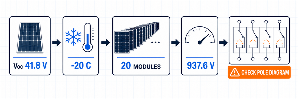
と極構成図から電圧定格を設定する寒冷時のPVストリング電圧計算とDC回路ブレーカーの極構成チェックoc ストリング電圧は、モジュールが開放状態で低温のときに最も高くなります。モジュールのSTC V.
のみから選択されたブレーカーは、寒い朝に定格不足になる可能性があります。oc モジュールが摂氏1度あたりのパーセントで負のV
V温度係数を提供する場合、予備計算は次のとおりです。 = Voc、STC × [1 + |βVoc| × (25 − Tmin)]
Voc,cold,module = Ns oc,cold,string温度係数を提供する場合、予備計算は次のとおりです。
× Vs ここで、Nmin は直列モジュール数、T.
遮断器の宣言された直流電圧は、承認された最大回路電圧以上でなければなりません。また、製造元が示す正確な極配置でその定格を達成する必要があります。一部の高電圧直流遮断器は、アーク遮断を分担するために複数の接点を直列に配置しています。4極本体が自動的に1000 Vまたは1500 Vの遮断器になるわけではありません。.
注文前に、以下を確認してください。
- 正確なモデルの定格動作直流電圧;
- その電圧で直列に使用される極数;
- 許容される正極および負極の導体経路;
- 極性の感度とライン/ロード方向;
- 絶縁機能が必要な場合の絶縁適合性の宣言.
既存の JUTRIONコールドストリング電圧計算ツール は、初期段階のVoc,cold,module 結果を提供できます。これはPV SPD電圧スクリーニング用に作成されましたが、コールドストリング電圧は遮断器、断路器、ケーブル、インバータのチェックにも入力されます。.
故障経路を使用して遮断器が回路を保護できるか判断する
遮断器の定格電流と遮断容量は異なる質問に答えます。
- 定格電流またはトリップ設定: can the device carry normal current and protect the circuit against applicable overcurrent?
- DC breaking capacity: can it safely interrupt the prospective fault current at the stated DC voltage and wiring condition?
Do not compare a 100 A breaker rating with a 50 A reverse-current contribution and conclude that the device can interrupt the fault. A normal-current label does not prove trip response, conductor protection or DC interruption performance.
At a string fault, healthy parallel strings may feed reverse current into the damaged string. An initial screen is:
I逆方向、画面 = (Np − 1) × Isc、文字列
This shows why reverse-current exposure grows as more strings are paralleled. It does not by itself select a breaker or fuse. The final design must consider the module’s maximum series-fuse rating, conductor capacity, protective-device characteristic and the requirements of the adopted installation rules.
At a combined output, identify every source that can feed the fault. PV modules are current-limited compared with a utility or battery, but parallel sub-arrays, connected power-conversion equipment and any storage interface can change the available current. If batteries are connected at DC level, stop treating the circuit as a PV-only example; battery fault-current assessment deserves its own design.
Do Not Assume a Large Breaking Number Solves a Poor Trip Decision
A breaker may have ample ultimate interruption capacity and still fail to protect the intended conductor because its trip threshold or time-current response is unsuitable. Conversely, a low-current breaker can have a normal rating close to the load yet lack the required DC breaking capacity at the actual voltage. Verify both the interruption rating and the protective characteristic.
PV faults can also occur near the lower end of a breaker’s operating range. Selectivity between string devices and an output breaker is not guaranteed simply because the output device has the larger ampere label. Use manufacturer coordination data where selective operation matters, and treat the claimed trip curve as model-specific evidence rather than a generic “C-curve for solar” rule.
IEC 60947-2:2024 applies to circuit breakers for instructed or skilled persons with rated voltages up to 1000 V AC or 1500 V DC. That product-standard scope supports the key procurement rule: obtain verified DC ratings for the exact breaker, not an AC breaking figure or a family-level marketing label.
Choose DC MCB or DC MCCB After the Duty Is Visible
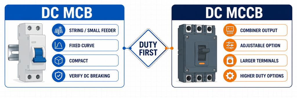
DC MCB versus DC MCCB comparison for solar string and combiner output protection“Use an MCB below 63 A and an MCCB above 63 A” is convenient, but it is not a universal engineering boundary. Product ranges overlap. Some DC MCB families extend above 63 A; some projects choose an MCCB at a lower current because they need a different breaking capacity, adjustable protection, larger terminals or accessories.
| Project need | DC MCB is the stronger shortlist when… | DC MCCB is the stronger shortlist when… |
|---|---|---|
| Installation format | A compact DIN-rail device fits the string or small feeder | A molded-case panel device, larger conductors or busbars are involved |
| Protection adjustment | The declared fixed characteristic suits the circuit | An available adjustable trip unit helps coordinate the feeder |
| Breaking duty | The model’s verified DC breaking capacity exceeds the fault level | The circuit requires a higher verified DC interruption duty |
| Control and indication | Basic handle position or modular auxiliary options are sufficient | Shunt trip, auxiliary contacts or remote operation are required and supported |
| Typical PV position | Individual string or lower-current branch | Combiner output or higher-current array feeder |
The decision is not about which family is “better.” It is about which verified product satisfies the location’s current window, voltage/pole arrangement, interruption duty, cable interface and control requirements. After those values are known, compare the available JUTRION DC MCB configurations と JUTRION DC MCCB configurations.
Decide Whether the Location Needs a Fuse, Breaker or Isolator
Three devices often appear in the same combiner box, but their jobs are not interchangeable.
- gPV fuse and holder: provides PV string or array overcurrent protection within its verified duty. It does not provide maintenance isolation unless the complete fuse-switch arrangement is designed for that function.
- DCサーキットブレーカー: provides automatic overcurrent operation plus switching within its declared ratings. It does not automatically satisfy a required isolating function unless it is declared suitable for isolation.
- DC switch-disconnector: provides manual load switching and isolation within its utilization rating. It does not provide automatic overload or short-circuit protection.
At string level, gPV fuses are common because parallel strings can feed reverse current into a faulted string and the module provides a maximum series-fuse rating. A resettable breaker may be useful where its PV duty and characteristic are verified, but “resettable” is not evidence that it coordinates better.
At a combiner output, a breaker may protect the combined cable and provide switching. Another design may use a switch-disconnector because overcurrent protection is located elsewhere. State which function the device performs; otherwise two suppliers can quote different architectures under the same “DC breaker” request.
Coordinate the Breaker with the Complete DC Path
A correct breaker can still be wrong in an incorrectly coordinated system. Complete five checks before freezing the model.
Cable
Verify conductor ampacity after ambient-temperature, grouping, installation and termination corrections. The breaker rating or setting must remain within the permitted protection relationship. Do not increase the breaker solely to stop nuisance trips without reviewing the enclosure temperature and cable.
Inverter
Compare cold string voltage with maximum DC input voltage. Compare the parallel-string operating current with the MPPT/input-current limit, and total Isc with the inverter’s permitted short-circuit current. The breaker does not authorize an array that exceeds the inverter data.
String fuses
Confirm whether each string needs reverse-current protection and whether the selected fuse/link remains below the module maximum series-fuse rating while carrying the required current under enclosure conditions. The common output breaker and string fuses normally protect different conductors.
PV DC SPD
An SPD limits transient overvoltage; it is not the normal overcurrent device. Follow the SPD manufacturer’s backup-protection instructions and check its short-circuit behavior. The guide to selecting a DC SPD for solar PV covers UCPV, Type 2/Type 1+2 and protection-level decisions.
Enclosure and assembly
Outdoor combiner boxes can run substantially hotter than the surrounding air. Use the breaker’s actual temperature/altitude data, terminal limits and mounting instructions. Closely spaced protective devices, solar heating, cable losses and restricted airflow all affect usable current. Review the complete PV combiner-box assembly, not only the breaker nameplate.
If a catalogue curve shows that the breaker carries less current at the expected internal temperature, apply that curve before choosing the frame. If no applicable curve or assembly data is available, increasing the breaker rating by an improvised percentage is not a defensible thermal design. The larger breaker may also require a larger conductor, terminal or enclosure and may no longer protect the original cable.
IEC 62548-1:2023 covers PV array design requirements including DC wiring, electrical protection devices, switching and earthing provisions. IEC 60364-7-712:2025 applies to electrical installations of PV systems. These installation contexts are distinct from the circuit-breaker product standard.
One Array, Three Different Breaker Decisions
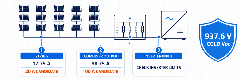
Solar DC breaker sizing example comparing string, combiner output and inverter input decisionsIllustrative design: each string has 20 identical modules. Module data states Voc、STC = 41.8 V, Isc = 14.2 A and βVoc = −0.27%/°C. The minimum design temperature is −20°C. Five compatible strings feed one inverter input through a combiner. For this example only, the project’s preliminary current method uses 1.25 × Isc.
First, establish the common voltage duty
Cold module Voc = 41.8 × [1 + 0.0027 × (25 − (−20))] = 46.88 V
Cold string Voc = 20 × 46.88 = 937.6 V
The strings are in parallel at the combiner, so their voltages do not add. The string device and the output device both require a verified voltage/pole arrangement above the approved maximum circuit voltage. A 1000 V DC class is the initial shortlist, subject to the project’s additional voltage treatment and the exact breaker diagram.
Position 1: one string
Preliminary string design current = 14.2 × 1.25 = 17.75 A
A 20 A PV-rated protective device is the first current candidate. Before choosing a DC MCB, compare this result with the module maximum series-fuse rating, conductor ampacity, required reverse-current protection and the exact trip characteristic. A gPV fuse may remain the better string-protection choice.
With five strings in parallel, the four healthy strings produce an initial reverse-current screen of:
(5 − 1) × 14.2 = 56.8 A
That figure explains why string protection deserves attention. It does not mean a 56.8 A string breaker should be fitted.
Position 2: combiner output
Total Isc = 5 × 14.2 = 71.0 A
Preliminary output design current = 71.0 × 1.25 = 88.75 A
A 100 A-class DC breaker is a current shortlist for the combined output. The handoff from MCB to MCCB now depends on the available product range, verified DC breaking capacity, required settings, terminal size and enclosure temperature—not on a universal 63 A rule.
Position 3: inverter input
The current arithmetic may be identical to the combiner output because it is the same feeder. The decision is not automatically identical. Confirm whether the inverter already provides a DC switch, whether an external breaker is required, the maximum input current and Isc, the permitted switching arrangement and the location needed for safe maintenance.
| 位置 | Calculated current starting point | Initial device direction | Decision that remains |
|---|---|---|---|
| One string | 17.75 A | 20 A PV protective device candidate | gPV fuse or DC MCB; module/cable coordination |
| コンバイナ出力 | 88.75 A | 100 A-class DC breaker candidate | MCB/MCCB, DC breaking capacity, settings and temperature |
| Inverter input | Same feeder current | Breaker or switch-disconnector as required | Inverter limits and whether protection already exists |
The calculation has produced three different functional decisions from one array. That is more useful than quoting one breaker size for “a 100 kW solar system.”
Read the Breaker Datasheet as a Connected Rating Set
Do not approve the device by circling one number. Read these ratings together:
- Ue: rated operational voltage for the stated DC pole arrangement;
- In or frame/setting: current rating and available adjustment under reference conditions;
- DC breaking capacity: declared interruption performance at the relevant DC voltage;
- trip characteristic: how and when the device operates, not simply a B/C/D letter borrowed from another family;
- isolation declaration: whether it can serve the required isolating function;
- pole and polarity diagram: the only valid connection for the declared high-voltage rating;
- temperature and altitude data: the basis for usable current in the real enclosure;
- terminals: conductor range, material, preparation and tightening torque;
- accessories: auxiliary contacts, shunt trip or remote operation where the system needs them.
A label such as “4P, 1000 V DC, 100 A” does not disclose the complete connected rating set. Ask for the exact technical sheet and wiring diagram for the ordered model.
Three Datasheet Warning Signs
- One breaking-capacity number with no DC voltage: interruption performance must refer to a stated voltage and test arrangement.
- A 1000 V claim with no pole diagram: the buyer cannot confirm how the arc chambers share voltage or where the conductors connect.
- One current rating with no reference temperature: the rooftop enclosure duty remains unknown.
These omissions do not automatically prove that a product is unsuitable, but they prevent an engineering selection. Resolve them before the device is installed in a live PV string.
よくある質問
ソーラーパネルにはどのサイズのDCブレーカーが必要ですか?
Use module Isc and the number of parallel strings on the protected path, then apply the current method required by the project. Select the next suitable rating only if it also protects the derated cable and stays within inverter and terminal limits. Check cold Voc, DC breaking capacity and pole wiring separately.
太陽光発電のDC側にACブレーカーを使用できますか?
製造元がその直流用途について、正確な機器、直流電圧、遮断容量、極構成を明示している場合に限ります。交流定格だけでは不十分です。持続する直流アークは遮断がより困難だからです。.
PVストリングにはヒューズを使用すべきか、それとも回路遮断器を使用すべきか?
gPVヒューズは、個別ストリングの逆電流保護に一般的です。PV定格の直流遮断器は、その特性、電圧、遮断責務、ケーブル/モジュールとの協調が適切な場合に選定されることがあります。答えは保護設計に依存し、リセット可能な機器への好みには依存しません。.
DC MCBの代わりにDC MCCBを選ぶべきなのはどのような場合ですか?
直流ミニチュアサーキットブレーカー(DC MCB)?
用途に応じて選定してください。より大きなフレーム、より高い検証済み遮断容量、調整可能な保護、より大きな端子、または制御用付属品が必要な場合、MCCBが有力な候補となります。一律の63 A境界に頼らないでください。.
1000 V PVストリングには2極または4極のブレーカーが必要ですか?
ブレーカーメーカーは、モデルの検証済みDC極配線図によってこれを決定します。1000 Vに達するために複数の極を直列に接続する必要がある製品もあれば、異なる構造を採用している製品もあります。極数だけで選ぶのではなく、正確な配線図と極性表示に従ってください。.
Complete the Selection at Each Position
For an individual string, resolve reverse-current protection and the module’s series-protection limit. At the combiner output, resolve combined current, cable protection and DC breaking duty. At the inverter input, resolve the equipment limits and the required isolation point.
Only then choose the product family. A compact DC MCB may fit the string or smaller feeder; a DC MCCB may better fit the combined output. The final model is the one whose current, voltage, interruption, poles and installed-condition ratings all refer to the same circuit—not five individually impressive numbers collected from different conditions.
