

Mabilis na Sagot sa Pagsusukat
Sukatin ang isang solar DC circuit breaker sa aktuwal nitong posisyon sa one-line diagram. Gamitin ang cold-corrected string Voc para sa boltahe, module Isc na minultiplika sa bilang ng parallel-string at sa kinakailangang factor ng proyekto para sa current, pagkatapos ay kumpirmahin ang proteksyon ng cable, DC breaking capacity, pole wiring at enclosure derating. Pumili lamang ng MCB o MCCB pagkatapos malaman ang mga tungkuling iyon.
Ang parehong PV array ay maaaring mangailangan ng 20 A device sa isang string at 100 A device sa combiner output. Ang parehong device ay nakakakita ng humigit-kumulang na parehong string voltage, ngunit hindi sila nagdadala ng parehong current o nagpoprotekta sa parehong conductor. Iyan ang dahilan kung bakit ang isang kahilingan tulad ng “1000 V DC solar breaker” ay hindi pa handa para sa pagpili ng modelo.
Ang unang tanong ay hindi Anong sukat ng breaker? Ito ay Saan ang breaker, at ano ang maaaring magpakain ng fault sa puntong iyon?
Ilagay ang Breaker sa PV Protection Map
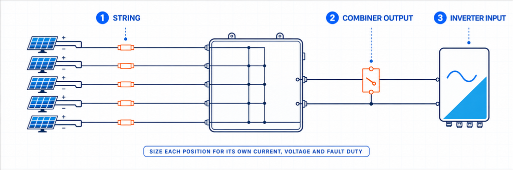
Mapa ng proteksyon ng Solar PV DC na nagpapakita ng mga posisyon ng string, combiner output at inverter input breakerAng isang solar array ay isang kadena ng mga circuit na magkakaiba sa elektrikal. Markahan ang iminungkahing breaker bago magbukas ng katalogo:
PV string → input ng string combiner → combined DC output → DC input ng inverter
Ang paglipat ng isang posisyon pakanan ay nagbabago sa daanan ng current. Ang mga module na nakaserye ay nagtataas ng boltahe. Ang mga compatible na string na nakaparallel ay nagtataas ng current. Ang isang breaker sa isang indibidwal na input ay karaniwang nagdadala ng isang string; ang isang breaker sa common output ay nagdadala ng lahat ng string na konektado sa output na iyon.
| Posisyon | Current sa pamamagitan ng device | Pangunahing tungkulin na dapat itatag | Karaniwang shortlist |
|---|---|---|---|
| Indibidwal na string | Isang string | Proteksyon sa reverse-current at paghihiwalay ng string | gPV fuse o PV-rated DC MCB kung saan pinapayagan ng disenyo |
| Output ng combiner | Kabuuan ng mga parallel string | Pinagsamang proteksyon ng feeder at output-cable | PV-rated DC MCB, DC MCCB o switch-disconnector na may hiwalay na proteksyon |
| DC input ng inverter | Current na itinalaga sa inverter input o MPPT path na iyon | Paghihiwalay ng kagamitan at koordinadong proteksyon | Breaker o switch-disconnector na tinukoy ng disenyo ng sistema |
Sinasadyang sinasabi ng talahanayan na “shortlist.” Ang isang circuit breaker ay hindi awtomatikong kinakailangan sa bawat posisyon. Ang isang string ay maaaring gumamit ng gPV fuses; ang isang inverter ay maaaring mayroon nang angkop na DC isolator; ang isang output ay maaaring mangailangan ng isolation habang ang overcurrent protection ay ibinibigay sa ibang lugar. Tukuyin muna ang nawawalang function bago pumili ng device.
Ang artikulo tungkol sa pag-size ng solar combiner-box ay nagpapaliwanag kung paano tinutukoy ng MPPT grouping kung aling mga string ang maaaring magbahagi ng isang output. Kumpletuhin muna ang desisyong iyon sa arkitektura. Hindi kayang itama ng isang breaker ang mga string na hindi dapat pinagsama sa parallel.
Itatag ang Current Window, Hindi Lamang ang Minimum na Ampere Rating
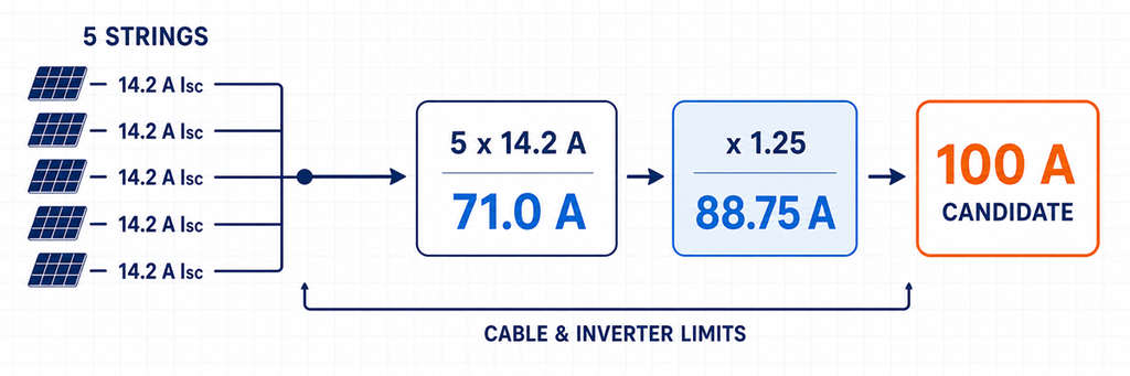
Pagsusukat ng current ng solar DC circuit breaker mula sa limang parallel string hanggang sa isang 100 amp na kandidatoAng pagkalkula ng current ay may dalawang panig. Dapat dalhin ng breaker ang design current sa ilalim ng mga naka-install na kondisyon, ngunit hindi ito dapat masyadong malaki na ang protektadong cable o konektadong kagamitan ay maiwan sa labas ng mga limitasyon nito.
Para sa magkatugmang PV strings:
Isc,path = Np × Isc,module
kung saan:
- Isc,path ay ang batayan ng short-circuit-current para sa napiling path sa amperes;
- Np ay ang bilang ng mga string na konektado nang parallel sa path na iyon;
- Isc,module ay ang module short-circuit current sa nakasaad nitong test condition.
Ang paraan ng pag-install ng proyekto ang siyang tumutukoy sa design-current treatment:
Idisenyo = Isc,path × Kproyekto
Kproyekto is not a number to guess. It represents the current factor required by the adopted installation rules and design basis. North American examples commonly show 1.25 or 1.56 depending on equipment rating and the calculation path. IEC-oriented projects must use the applicable installation requirements, module data and manufacturer instructions rather than relabeling one of those figures as a universal “IEC multiplier.”
The useful selection window is:
Required carrying current ≤ usable breaker rating or setting ≤ permitted protected-circuit limit
The upper boundary may be set by derated cable ampacity, terminal rating, inverter input limit or another protected component. Selecting the next standard breaker above Idisenyo is only valid when the upper boundary still passes.
Series Modules Do Not Multiply Breaker Current
Twenty modules in series do not produce twenty times the module current. They increase string voltage while string current remains based on one module. Five identical strings in parallel produce approximately five times the current. This is why dividing array watts by an assumed DC voltage is a poor substitute for the module datasheet and string schedule.
Use Isc and Imp for Different Checks
Isc is the short-circuit-current starting point used in PV overcurrent design. Imp describes operating current near maximum power and helps verify inverter MPPT loading and normal operation. Keep both values on the worksheet. Do not replace the protection basis with the lower Imp, and do not forget the inverter’s operating-current limit after calculating from Isc.
Keep IEC and North American Examples in Their Own Lanes
Eaton’s North American PV application guide, for example, distinguishes 80%-rated and 100%-rated molded-case breakers. Its worked method uses 1.56 × Isc for an 80%-rated breaker and 1.25 × Isc for a 100%-rated breaker, together with conductor and temperature checks. Those figures are useful inside that NEC/UL and product context. They should not be detached from it and published as a global PV rule.
For an IEC project, begin with the edition adopted by the contract or jurisdiction. The public scope of IEC 60364-7-712 confirms that it addresses PV electrical installations, but a scope page does not establish the complete calculation for a specific project. Record the actual design rule beside Kproyekto; this keeps the arithmetic reviewable and prevents a supplier from silently switching methods.
Set the Voltage Rating from Cold Voc and the Pole Diagram
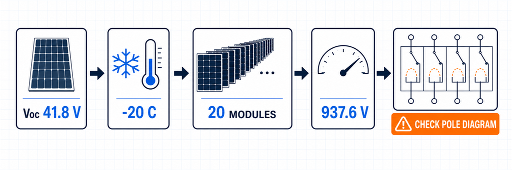
Cold-weather PV string voltage calculation and DC circuit breaker pole configuration checkString voltage is highest when the modules are open-circuit and cold. A breaker selected from the module’s STC Voc alone can be underrated on a cold morning.
Where the module provides a negative Voc temperature coefficient in percent per degree Celsius, a preliminary calculation is:
Voc,cold,module = Voc,STC × [1 + |βVoc| × (25 − Tmin)]
Voc,cold,string = Ns × Voc,cold,module
where Ns is the number of modules in series and Tmin is the project’s minimum design temperature. Enter −0.27%/°C as 0.0027. If the module manufacturer or adopted design method specifies another temperature calculation, use it consistently across the inverter and every DC component.
The breaker’s declared DC voltage must be at least the approved maximum circuit voltage. It must also achieve that rating in the exact pole arrangement shown by its manufacturer. Some high-voltage DC breakers place several contacts in series to share arc interruption. A four-pole body does not automatically equal a 1000 V or 1500 V breaker.
Before ordering, confirm:
- rated operational DC voltage for the exact model;
- number of poles used in series at that voltage;
- permitted positive and negative conductor path;
- polarity sensitivity and line/load direction;
- declared suitability for isolation where that function is required.
The existing JUTRION cold-string voltage calculator can provide a first-pass Voc,cold,string result. It was created for PV SPD voltage screening, but the cold string voltage is also an input to breaker, isolator, cable and inverter checks.
Use the Fault Path to Decide Whether a Breaker Can Protect the Circuit
A breaker’s rated current and its breaking capacity answer different questions:
- Rated current or trip setting: can the device carry normal current and protect the circuit against applicable overcurrent?
- DC breaking capacity: can it safely interrupt the prospective fault current at the stated DC voltage and wiring condition?
Do not compare a 100 A breaker rating with a 50 A reverse-current contribution and conclude that the device can interrupt the fault. A normal-current label does not prove trip response, conductor protection or DC interruption performance.
At a string fault, healthy parallel strings may feed reverse current into the damaged string. An initial screen is:
Ibaligtad, screen = (Np − 1) × Isc, string
This shows why reverse-current exposure grows as more strings are paralleled. It does not by itself select a breaker or fuse. The final design must consider the module’s maximum series-fuse rating, conductor capacity, protective-device characteristic and the requirements of the adopted installation rules.
At a combined output, identify every source that can feed the fault. PV modules are current-limited compared with a utility or battery, but parallel sub-arrays, connected power-conversion equipment and any storage interface can change the available current. If batteries are connected at DC level, stop treating the circuit as a PV-only example; battery fault-current assessment deserves its own design.
Do Not Assume a Large Breaking Number Solves a Poor Trip Decision
A breaker may have ample ultimate interruption capacity and still fail to protect the intended conductor because its trip threshold or time-current response is unsuitable. Conversely, a low-current breaker can have a normal rating close to the load yet lack the required DC breaking capacity at the actual voltage. Verify both the interruption rating and the protective characteristic.
PV faults can also occur near the lower end of a breaker’s operating range. Selectivity between string devices and an output breaker is not guaranteed simply because the output device has the larger ampere label. Use manufacturer coordination data where selective operation matters, and treat the claimed trip curve as model-specific evidence rather than a generic “C-curve for solar” rule.
IEC 60947-2:2024 applies to circuit breakers for instructed or skilled persons with rated voltages up to 1000 V AC or 1500 V DC. That product-standard scope supports the key procurement rule: obtain verified DC ratings for the exact breaker, not an AC breaking figure or a family-level marketing label.
Choose DC MCB or DC MCCB After the Duty Is Visible
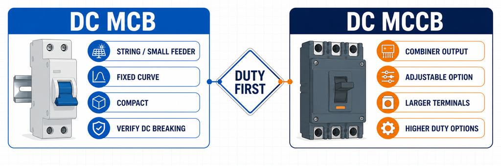
DC MCB versus DC MCCB comparison for solar string and combiner output protection“Use an MCB below 63 A and an MCCB above 63 A” is convenient, but it is not a universal engineering boundary. Product ranges overlap. Some DC MCB families extend above 63 A; some projects choose an MCCB at a lower current because they need a different breaking capacity, adjustable protection, larger terminals or accessories.
| Project need | DC MCB is the stronger shortlist when… | DC MCCB is the stronger shortlist when… |
|---|---|---|
| Installation format | A compact DIN-rail device fits the string or small feeder | A molded-case panel device, larger conductors or busbars are involved |
| Protection adjustment | The declared fixed characteristic suits the circuit | An available adjustable trip unit helps coordinate the feeder |
| Breaking duty | The model’s verified DC breaking capacity exceeds the fault level | The circuit requires a higher verified DC interruption duty |
| Control and indication | Basic handle position or modular auxiliary options are sufficient | Shunt trip, auxiliary contacts or remote operation are required and supported |
| Typical PV position | Individual string or lower-current branch | Combiner output or higher-current array feeder |
The decision is not about which family is “better.” It is about which verified product satisfies the location’s current window, voltage/pole arrangement, interruption duty, cable interface and control requirements. After those values are known, compare the available JUTRION DC MCB configurations at JUTRION DC MCCB configurations.
Decide Whether the Location Needs a Fuse, Breaker or Isolator
Three devices often appear in the same combiner box, but their jobs are not interchangeable.
- gPV fuse and holder: provides PV string or array overcurrent protection within its verified duty. It does not provide maintenance isolation unless the complete fuse-switch arrangement is designed for that function.
- DC circuit breaker: provides automatic overcurrent operation plus switching within its declared ratings. It does not automatically satisfy a required isolating function unless it is declared suitable for isolation.
- DC switch-disconnector: provides manual load switching and isolation within its utilization rating. It does not provide automatic overload or short-circuit protection.
At string level, gPV fuses are common because parallel strings can feed reverse current into a faulted string and the module provides a maximum series-fuse rating. A resettable breaker may be useful where its PV duty and characteristic are verified, but “resettable” is not evidence that it coordinates better.
At a combiner output, a breaker may protect the combined cable and provide switching. Another design may use a switch-disconnector because overcurrent protection is located elsewhere. State which function the device performs; otherwise two suppliers can quote different architectures under the same “DC breaker” request.
Coordinate the Breaker with the Complete DC Path
A correct breaker can still be wrong in an incorrectly coordinated system. Complete five checks before freezing the model.
Cable
Verify conductor ampacity after ambient-temperature, grouping, installation and termination corrections. The breaker rating or setting must remain within the permitted protection relationship. Do not increase the breaker solely to stop nuisance trips without reviewing the enclosure temperature and cable.
Inverter
Compare cold string voltage with maximum DC input voltage. Compare the parallel-string operating current with the MPPT/input-current limit, and total Isc with the inverter’s permitted short-circuit current. The breaker does not authorize an array that exceeds the inverter data.
String fuses
Confirm whether each string needs reverse-current protection and whether the selected fuse/link remains below the module maximum series-fuse rating while carrying the required current under enclosure conditions. The common output breaker and string fuses normally protect different conductors.
PV DC SPD
An SPD limits transient overvoltage; it is not the normal overcurrent device. Follow the SPD manufacturer’s backup-protection instructions and check its short-circuit behavior. The guide to selecting a DC SPD for solar PV covers UCPV, Type 2/Type 1+2 and protection-level decisions.
Enclosure and assembly
Outdoor combiner boxes can run substantially hotter than the surrounding air. Use the breaker’s actual temperature/altitude data, terminal limits and mounting instructions. Closely spaced protective devices, solar heating, cable losses and restricted airflow all affect usable current. Review the complete PV combiner-box assembly, not only the breaker nameplate.
If a catalogue curve shows that the breaker carries less current at the expected internal temperature, apply that curve before choosing the frame. If no applicable curve or assembly data is available, increasing the breaker rating by an improvised percentage is not a defensible thermal design. The larger breaker may also require a larger conductor, terminal or enclosure and may no longer protect the original cable.
IEC 62548-1:2023 covers PV array design requirements including DC wiring, electrical protection devices, switching and earthing provisions. IEC 60364-7-712:2025 applies to electrical installations of PV systems. These installation contexts are distinct from the circuit-breaker product standard.
One Array, Three Different Breaker Decisions
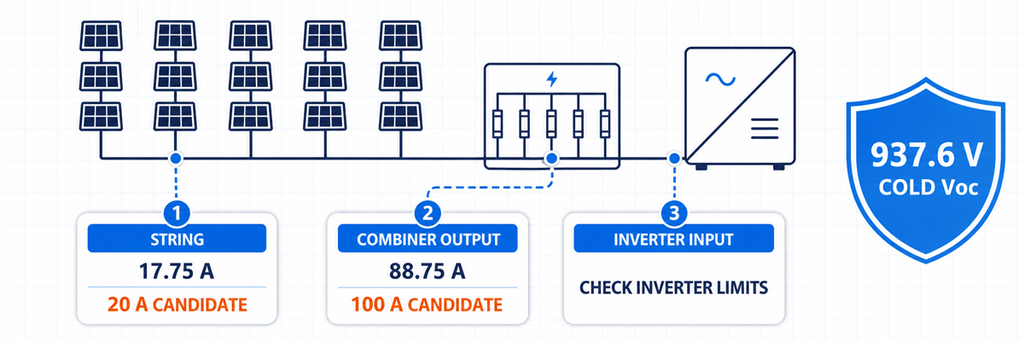
Solar DC breaker sizing example comparing string, combiner output and inverter input decisionsIllustrative design: each string has 20 identical modules. Module data states Voc,STC = 41.8 V, Isc = 14.2 A and βVoc = −0.27%/°C. The minimum design temperature is −20°C. Five compatible strings feed one inverter input through a combiner. For this example only, the project’s preliminary current method uses 1.25 × Isc.
First, establish the common voltage duty
Cold module Voc = 41.8 × [1 + 0.0027 × (25 − (−20))] = 46.88 V
Cold string Voc = 20 × 46.88 = 937.6 V
The strings are in parallel at the combiner, so their voltages do not add. The string device and the output device both require a verified voltage/pole arrangement above the approved maximum circuit voltage. A 1000 V DC class is the initial shortlist, subject to the project’s additional voltage treatment and the exact breaker diagram.
Position 1: one string
Preliminary string design current = 14.2 × 1.25 = 17.75 A
A 20 A PV-rated protective device is the first current candidate. Before choosing a DC MCB, compare this result with the module maximum series-fuse rating, conductor ampacity, required reverse-current protection and the exact trip characteristic. A gPV fuse may remain the better string-protection choice.
With five strings in parallel, the four healthy strings produce an initial reverse-current screen of:
(5 − 1) × 14.2 = 56.8 A
That figure explains why string protection deserves attention. It does not mean a 56.8 A string breaker should be fitted.
Position 2: combiner output
Total Isc = 5 × 14.2 = 71.0 A
Preliminary output design current = 71.0 × 1.25 = 88.75 A
A 100 A-class DC breaker is a current shortlist for the combined output. The handoff from MCB to MCCB now depends on the available product range, verified DC breaking capacity, required settings, terminal size and enclosure temperature—not on a universal 63 A rule.
Position 3: inverter input
The current arithmetic may be identical to the combiner output because it is the same feeder. The decision is not automatically identical. Confirm whether the inverter already provides a DC switch, whether an external breaker is required, the maximum input current and Isc, the permitted switching arrangement and the location needed for safe maintenance.
| Posisyon | Calculated current starting point | Initial device direction | Decision that remains |
|---|---|---|---|
| Isang string | 17.75 A | 20 A PV protective device candidate | gPV fuse or DC MCB; module/cable coordination |
| Output ng combiner | 88.75 A | 100 A-class DC breaker candidate | MCB/MCCB, DC breaking capacity, settings and temperature |
| Inverter input | Same feeder current | Breaker or switch-disconnector as required | Inverter limits and whether protection already exists |
The calculation has produced three different functional decisions from one array. That is more useful than quoting one breaker size for “a 100 kW solar system.”
Read the Breaker Datasheet as a Connected Rating Set
Do not approve the device by circling one number. Read these ratings together:
- Ue: rated operational voltage for the stated DC pole arrangement;
- In or frame/setting: current rating and available adjustment under reference conditions;
- DC breaking capacity: declared interruption performance at the relevant DC voltage;
- trip characteristic: how and when the device operates, not simply a B/C/D letter borrowed from another family;
- isolation declaration: whether it can serve the required isolating function;
- pole and polarity diagram: the only valid connection for the declared high-voltage rating;
- temperature and altitude data: the basis for usable current in the real enclosure;
- terminals: conductor range, material, preparation and tightening torque;
- accessories: auxiliary contacts, shunt trip or remote operation where the system needs them.
A label such as “4P, 1000 V DC, 100 A” does not disclose the complete connected rating set. Ask for the exact technical sheet and wiring diagram for the ordered model.
Three Datasheet Warning Signs
- One breaking-capacity number with no DC voltage: interruption performance must refer to a stated voltage and test arrangement.
- A 1000 V claim with no pole diagram: the buyer cannot confirm how the arc chambers share voltage or where the conductors connect.
- One current rating with no reference temperature: the rooftop enclosure duty remains unknown.
These omissions do not automatically prove that a product is unsuitable, but they prevent an engineering selection. Resolve them before the device is installed in a live PV string.
Mga Madalas Itanong
Anong laki ng DC breaker ang kailangan ko para sa mga solar panel?
Use module Isc and the number of parallel strings on the protected path, then apply the current method required by the project. Select the next suitable rating only if it also protects the derated cable and stays within inverter and terminal limits. Check cold Voc, DC breaking capacity and pole wiring separately.
Maaari ba akong gumamit ng AC breaker sa solar DC side?
Lamang kapag tahasang idineklara ng tagagawa ang eksaktong device, DC boltahe, breaking capacity at pole arrangement para sa DC application na iyon. Ang AC rating lamang ay hindi sapat dahil ang tuluy-tuloy na DC arc ay mas mahirap putulin.
Should a PV string use a fuse or a circuit breaker?
gPV fuses are common for individual-string reverse-current protection. A PV-rated DC breaker may be selected when its characteristic, voltage, breaking duty and cable/module coordination are suitable. The answer depends on the protection design, not on a preference for resettable devices.
When should I choose a DC MCCB instead of a DC MCB?
DC MCB?
Choose from the duty. An MCCB becomes the stronger candidate when the output needs a larger frame, higher verified breaking capacity, adjustable protection, larger terminals or control accessories. Do not rely on a universal 63 A boundary.
Do I need a 2-pole or 4-pole breaker for a 1000 V PV string?
The breaker manufacturer decides this through the model’s verified DC pole diagram. Some products require multiple poles in series to reach 1000 V; others use a different construction. Follow the exact diagram and polarity markings rather than choosing by pole count alone.
Complete the Selection at Each Position
For an individual string, resolve reverse-current protection and the module’s series-protection limit. At the combiner output, resolve combined current, cable protection and DC breaking duty. At the inverter input, resolve the equipment limits and the required isolation point.
Only then choose the product family. A compact DC MCB may fit the string or smaller feeder; a DC MCCB may better fit the combined output. The final model is the one whose current, voltage, interruption, poles and installed-condition ratings all refer to the same circuit—not five individually impressive numbers collected from different conditions.
